WEEK 15
Interface and application programming
Group Assignment:
- Compare as many tool options as possible.
Individual Assignment:
- Write an application that interfaces a user with an input &/or output device that you made.
This week, we tested some programs for designing interfaces, like App Inventor, Thony, and Processing. Additionally, for the individual part, I connected an analog sensor and displayed the value read on a simple interface designed in Processing.
Group Assignment
This week, I worked with Naldi to develop the group section. You can find our work here.
Individual Assignment
PROCESSIGN
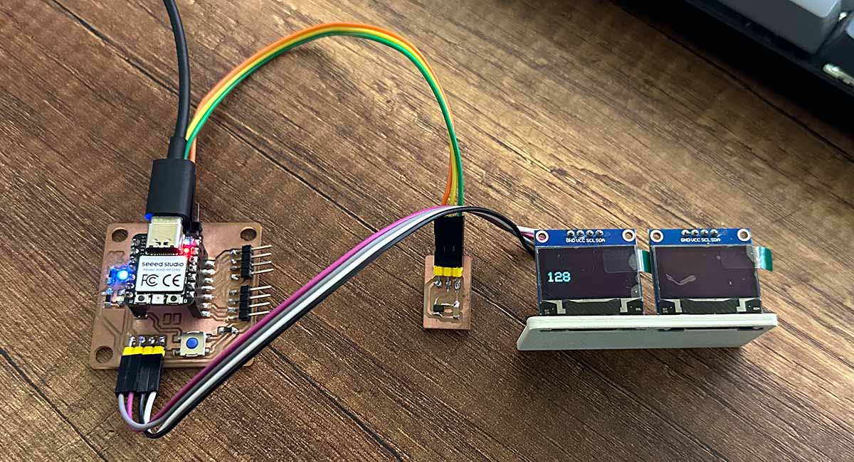
For the individual project, I designed a simple interface to visualize the data read by a Hall effect sensor. To do this, I used the board we made during electronics design week. I created the interface in Processing, and the program for the Xiao RP2040.
Processing is an IDE that's quite easy to use, open-source, and popular in the field of visual art and design. Processing allows for the creation of buttons, windows, and graphics, and it also supports connecting to ports for serial communication.

The following is the Processing code that allows us to connect to the port where the microcontroller is connected. The "draw" function draws a circle in the center of a 720 x 480 window and also displays text with the value read from the sensor. The color and diameter of the circle are functions of the value read.
//Program in processing
import processing.serial.*;

Serial myPort;    //Create object from Serial class
static String val;    //Data received from the serial port
int sensorVal = 0;

void setup(){
size(720, 480);
noStroke();
noFill();
String portName = "COM7";
myPort = new Serial(this, portName, 9600);
}

void draw(){
if ( myPort.available() > 0) {  // If data is available,
val = myPort.readStringUntil('\n');
try {
sensorVal = Integer.valueOf(val.trim());
}
catch(Exception e) {
;
}
println(sensorVal);
println(width);
}
background(0);
// Scale the sensor value from 0 to 255 to a range between 0 and width/2=360
float c = map(sensorVal, 0, 255, 0, width/2);
c = round(c);
fill(100, c, 0);
ellipse(width/2, height/2, c, c);

fill(255);
textSize(50);
text("Sensor Value: "+ sensorVal, 10, 40);

fill(255);
textSize(50);
text("Circle diameter: "+ c, 10, 100);
}
It's also necessary to create a program for the microcontroller. The following is a variation of the code I wrote during the input devices week. It reads the sensor, displays the data on the SSD1306 screen, writes it to the serial port, and finally varies the brightness of an LED based on the value read.
//Program hall effect
#include <Wire.h>
#include <Adafruit_GFX.h>
#include <Adafruit_SSD1306.h>

#define SCREEN_WIDTH 128 // OLED display width, in pixels
#define SCREEN_HEIGHT 64 // OLED display height, in pixels
#define OLED_RESET -1 // Reset pin # (or -1 if sharing Arduino reset pin)

Adafruit_SSD1306 display(SCREEN_WIDTH, SCREEN_HEIGHT, &Wire, OLED_RESET);

int sensorPin = 27; // analog input pin RP2040 pin 27
int val = 0;

void setup() {

display.begin(SSD1306_SWITCHCAPVCC, 0x3C);
delay(2000);

display.clearDisplay();
display.setTextColor(WHITE);

Serial.begin(9600); // initialize serial communications

pinMode(28,OUTPUT);
}

void loop() {

display.clearDisplay();
val = analogRead(sensorPin); // read the value from the sensor
val = map(val,0, 1023, 0, 255);
Serial.println(val); // print value to Serial Monitor
analogWrite(28,val);

display.setTextSize(2);
display.setCursor(0, 28);
display.print(val);

display.display();
delay(100);
}
Here is the result: as you can see, the circle changes when moving a magnet closer to or farther away from the sensor. The color also changes accordingly.
GUIZERO AND THONY
Another test I did was to control something on the board from the interface. To do this, I developed a simple interface in Thony and turned on and turned off an LED on the board.
The first thing I did was develop the following program that turns an LED on and off based on the value of a variable read from the serial port.
//Program to turn on and turn off a led
#define led 28
void setup() {
pinMode(led, OUTPUT);
Serial.begin(9600);
digitalWrite(led, LOW);
}
void loop() {
if(Serial.available()>0){
char option = Serial.read();
if(option == '1'){
digitalWrite(led, HIGH);
}
else{
digitalWrite(led, LOW);
}
}
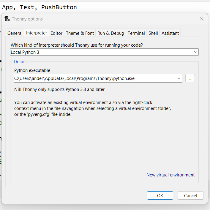
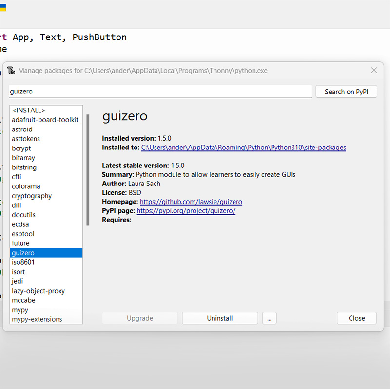
}Before writing the code in Thony, I made sure that the interpreter was set to Python 3. I also installed the guizero library, which allows us to create an interface to control the board from the computer.
The following is the interface. It essentially has two buttons: one to turn the LED on and the other to turn it off.
//Program in Thony and Guizero
from guizero import App, Text, PushButton
import serial, time

Xiaorp2040 = serial.Serial('COM7', 9600)
time.sleep(1)

def turn_on():
	Xiaorp2040.write(b'1')
	print("LED encendido")

def turn_off():
	Xiaorp2040.write(b'0')
	print("LED apagado")

ventana = App("Interface Guizero",width=400, height=300, layout="grid")
ventana.bg = "#A491DF"

titulo = Text(ventana, text="LED STATE", grid=[0, 0], align="left")

button = PushButton(ventana, turn_on, text="LED ON", grid=[1,2])
button.bg = "#A659DE"

button = PushButton(ventana, turn_off, text="LED OFF",grid=[2,2])
button.bg = "#4883E0"

ventana.display()
Xiaorp2040.close()
This is the result of the interface. I was surprised at how quickly it responds.