WEEK 13
Molding and casting
Group Assignment:
- Review the safety data sheets for each of your molding and casting materials.
- Make and compare test casts with each of them compare printing vs machining molds.
Individual Assignment:
- Design a mold around the process you'll be using, produce it with a smooth surface finish, and use it to cast parts.
- Extra credit: use more then two mold parts.
This week was really enjoyable because we did a lot of different things, from 3D designing and printing to milling, making silicone molds, and finally creating pieces in cement. In the group part, we conducted tests to compare molds made with 3D printing and those made with machining.
Group Assignment
This week, I worked with Naldi to develop the group project. You can find our work here.
Individual Assignment
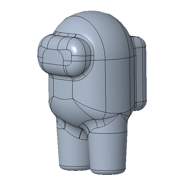
For the individual assignment, I wanted to design a character from the video game Among Us, which was very popular during the pandemic. It's a pretty fun game that I played online with my friends. The model is quite simple, and I made it using Creo with basic operations like extrusions, revolutions, and fillets.
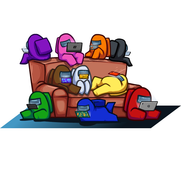
For the design, I used some images from the game's website as a reference (image on the left). The image on the right is the final model I made. It's approximately 65 mm x 35 mm in size. To make the silicone molds, I used both 3D printing with PLA and milling from a wax bar.
3D PRINTING
For the mold design, I used Creo, which is a program I really like and am most familiar with. I designed two parts with the following considerations:
- The box walls are 2mm thick, as it will be printed in PLA, which is sufficiently strong for our purposes.
- It has rectangular alignment slots about 8mm wide.
- I also modeled some conical shapes at the feet that will leave holes in the silicone mold halves, which will be used to pour in the material.
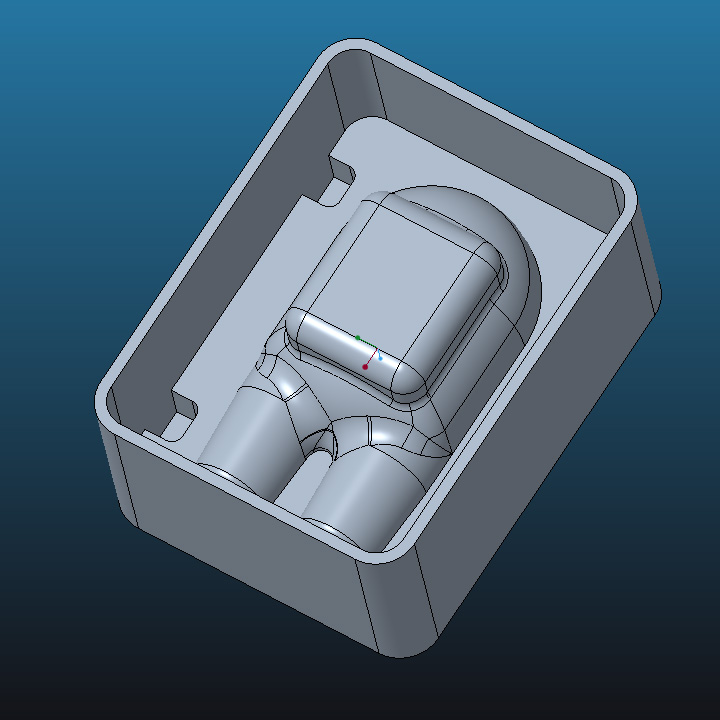
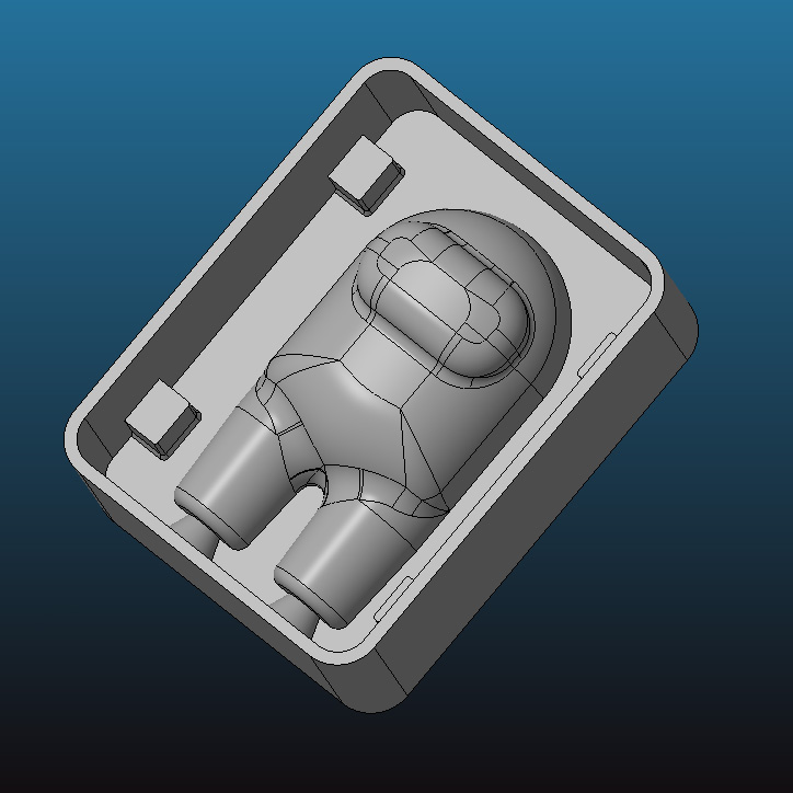
After converting the models to STL format, I printed them using a Bambu Lab P1S, utilizing the highest available quality, which has a layer height of 0.08 mm. The printed models have a very good surface finish, although in some curved areas like on the backpack and the glasses, the layer lines are visible.
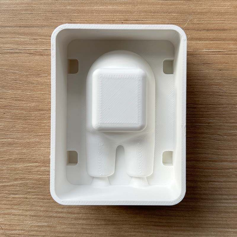
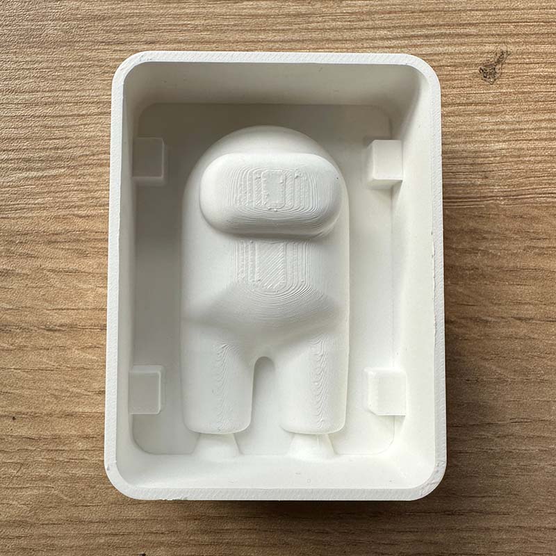
With the printed models, I started making the silicone molds. For this, I used RTV (room temperature vulcanization) silicone and its catalyst. The manufacturer recommends a ratio of 100:3, so we mixed 100 g of silicone with 3 g of catalyst.
After pouring the silicone, we obtained both halves of the molds. The surface finish is quite good, but it also replicates the same layer lines from the printing that have the negatives.
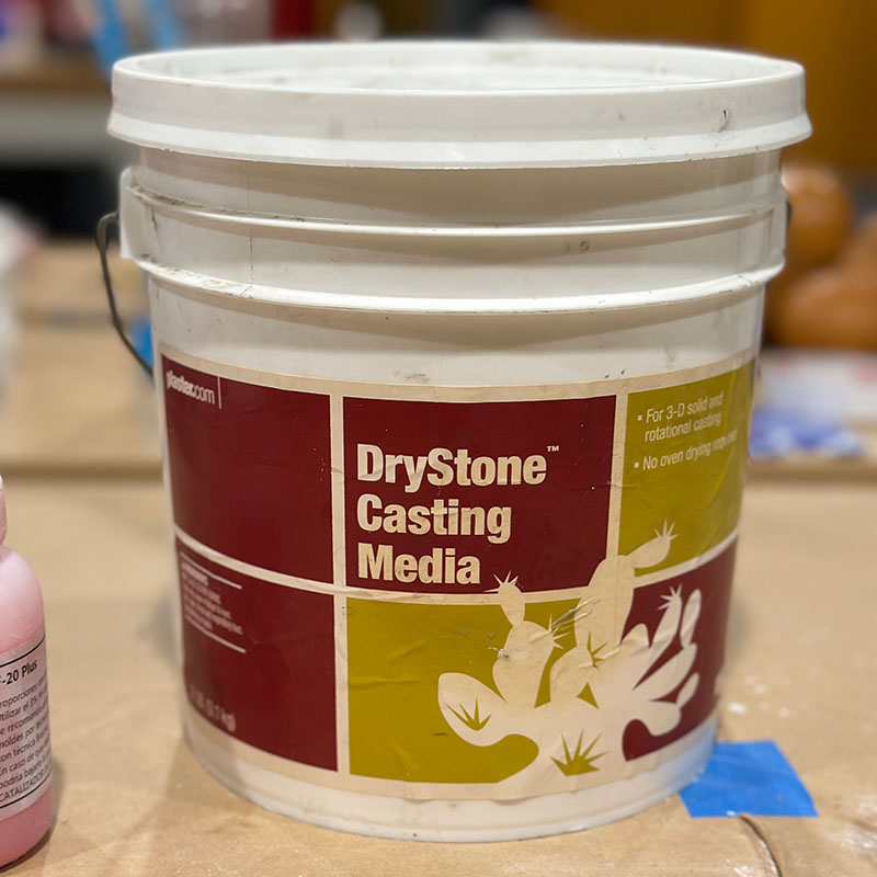
For the final material of the pieces, we chose DryStone casting media, which has a finish very similar to cement but is lighter and easier to work with as it dries quickly. At this point, I encountered some issues when pouring the material, as the holes I made were quite small and the mixed material turned out to be more viscous than I had planned. For the mix, the manufacturer recommends using a ratio of 100:20, meaning 20 parts water to 100 parts powder.
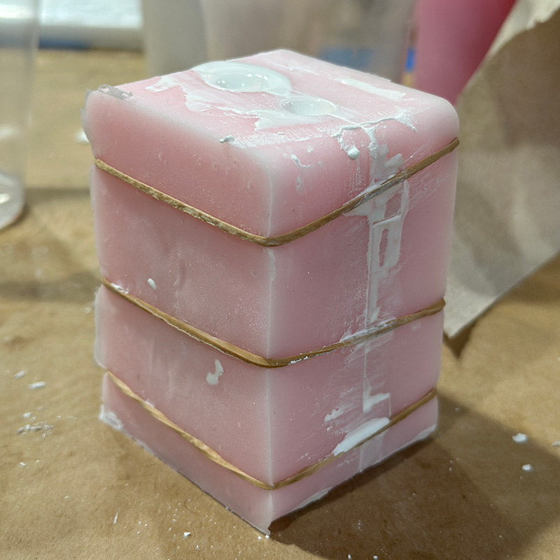
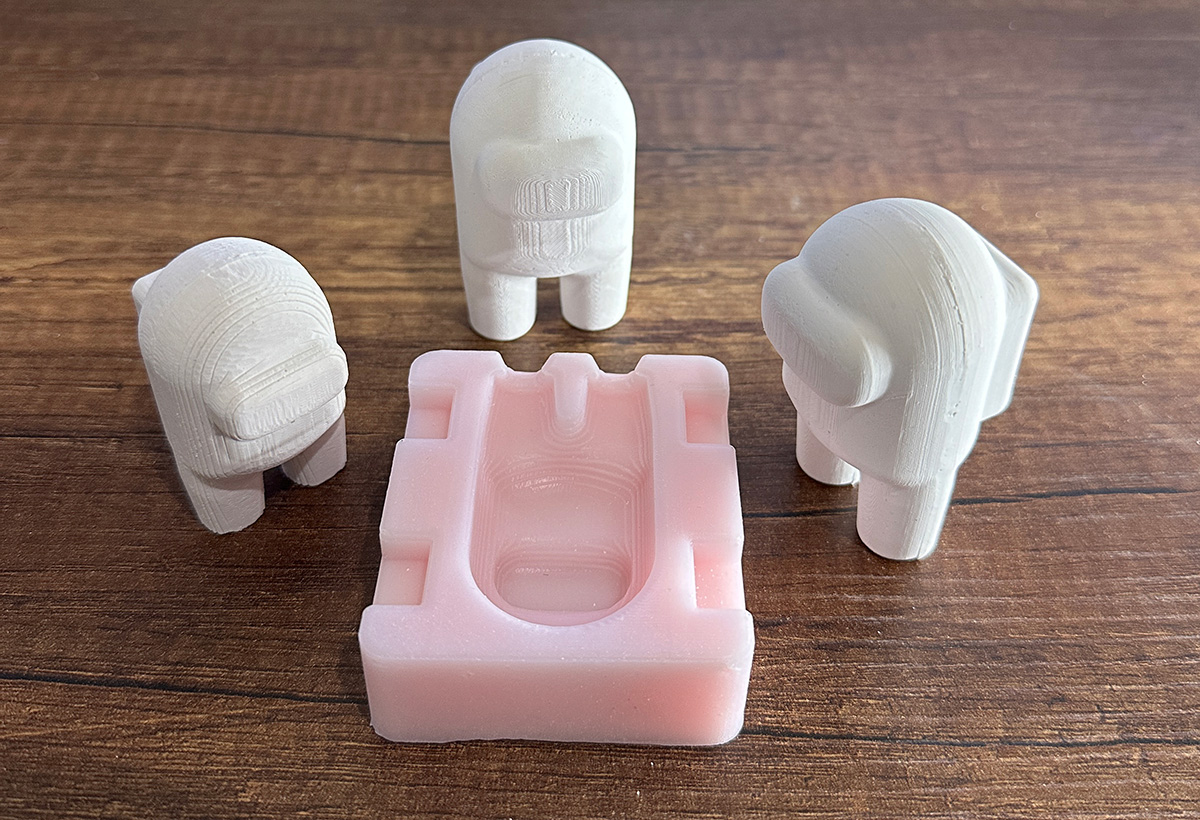
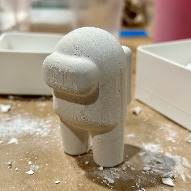
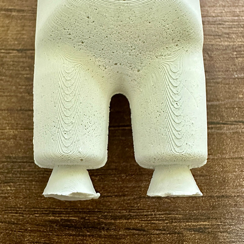
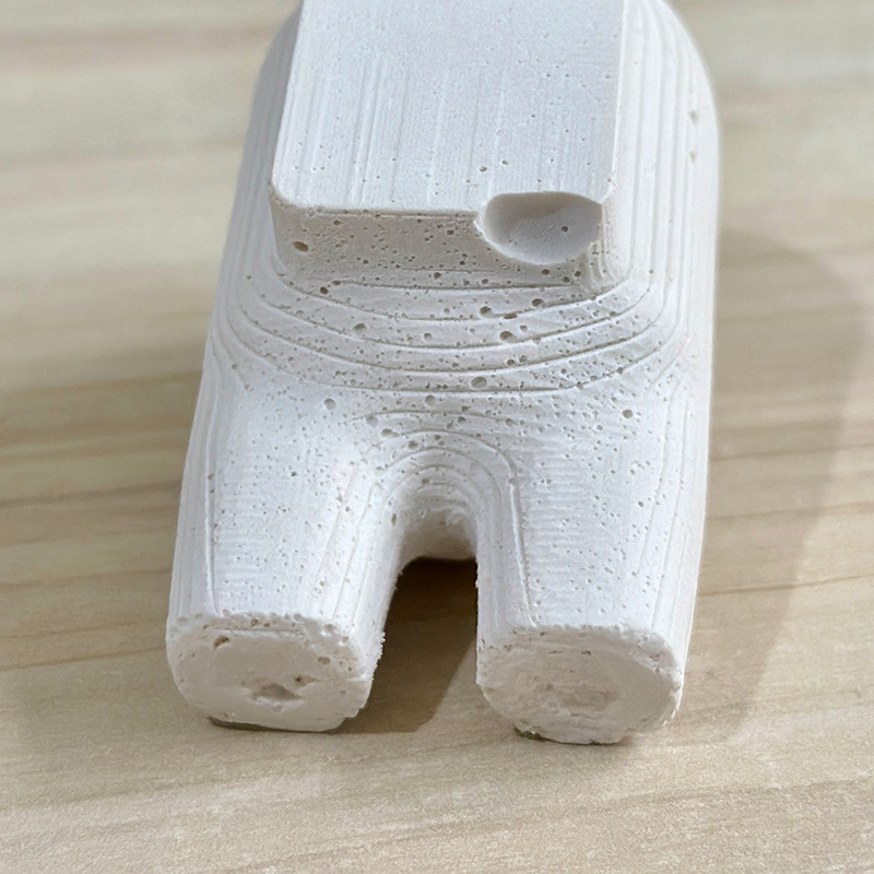
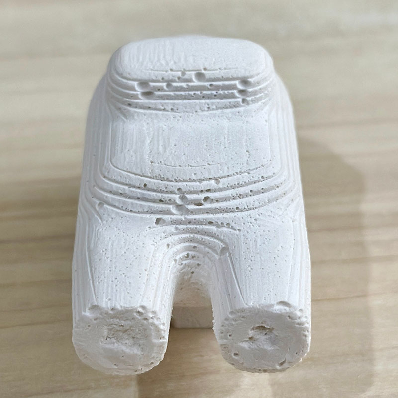
The result was as follows, as you can see in the images, the layer lines are marked in some of the cuved areas, but this can be improved using sandpaper. There are also some bubbles in some areas. The seam created along the mold partition line is noticeable but very easy to remove. Overall, I think the result is quite good.
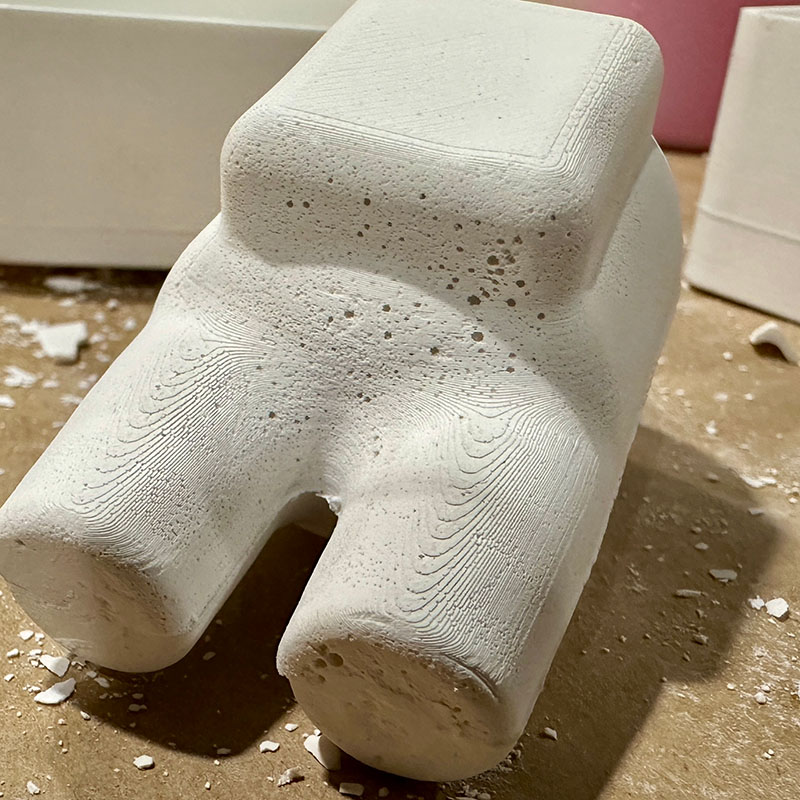
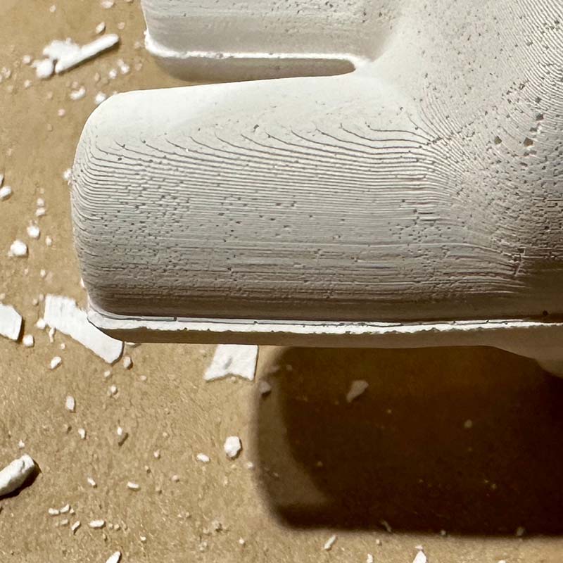
MACHINING
For the molds I made with machining, I designed another negative. This one has the both cavities in a single block, I did this way to fit the wax blocks we have in the lab. I also wanted to avoid the work of milling each mold individually. I made a slight reduction to the model to fit the dimensions of the wax block. In this case, I made the walls 8 mm thick since wax is a litle bit fragile.
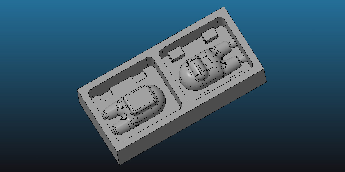
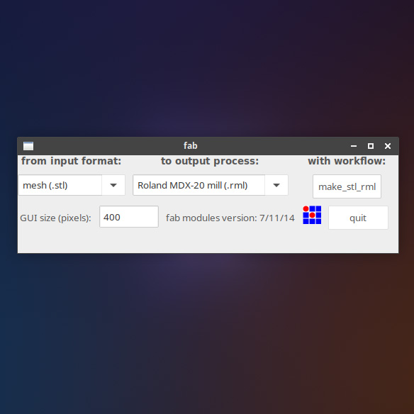
To mill the blocks, I used the Modela MDX-20 and a version of Fab Modules to control it. Here are the steps I followed:
- Open Fab Modules with the settings shown in the left-hand image.
- Calibrate the tool on the Z-axis, which is done manually.
- Select the tool, the units, and the type of milling (1/8, Wax, rough; mm, 1/8, Wax, finish).
- Load the STL model.
- Position the model correctly (x, -x, y, -y, z, -z).
- Press "Make .png".
- Press "Make .path".
- SPress "Make.rml".
- Press "send".
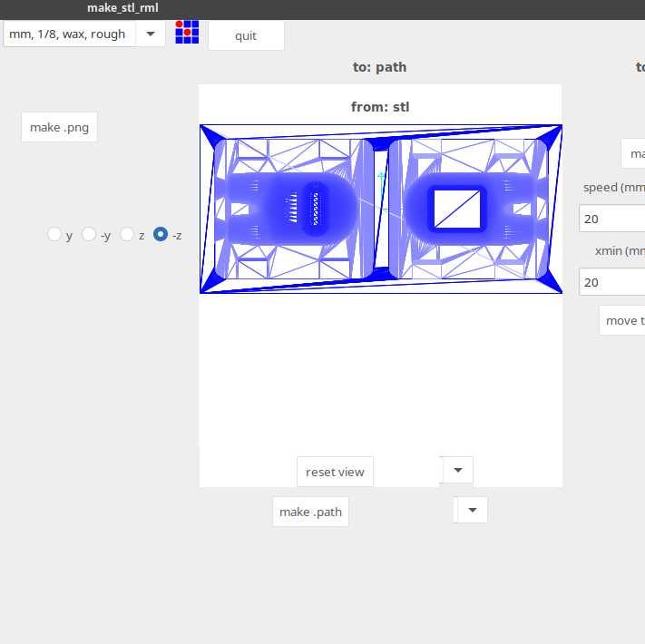
For the roughing, I used a 1/8" flat end mill and the result is as follows. The total milling process took 90 minutes.
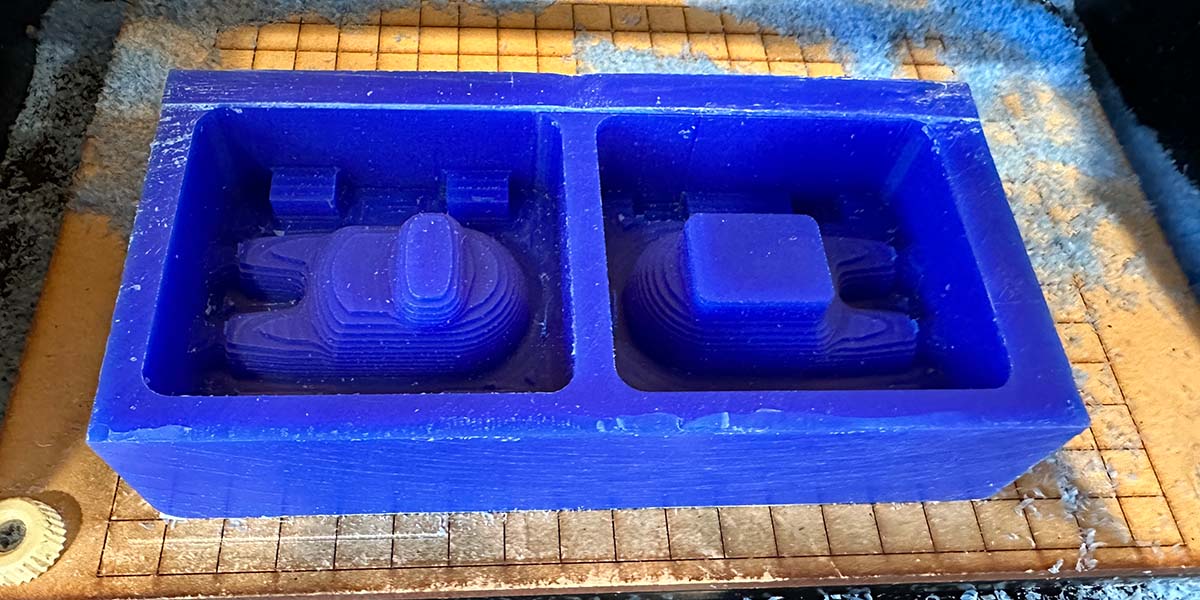
For the finishing, I used a 1/8” round-end mill. The steps are the same as those described for the roughing process, but in this case, I set the step over to 0.90. The entire finishing process also took 90 minutes. Here, I noticed that after the finishing process, some lines from the roughing process were still visible. This is due to the Z-axis not being well calibrated. For the finishing process, it's necessary to recalibrate the Z-axis manually and likely position the mill a few millimeters higher. In this case, I believed these lines would leave an interesting texture on the final finish of the pieces, so I decided to leave them
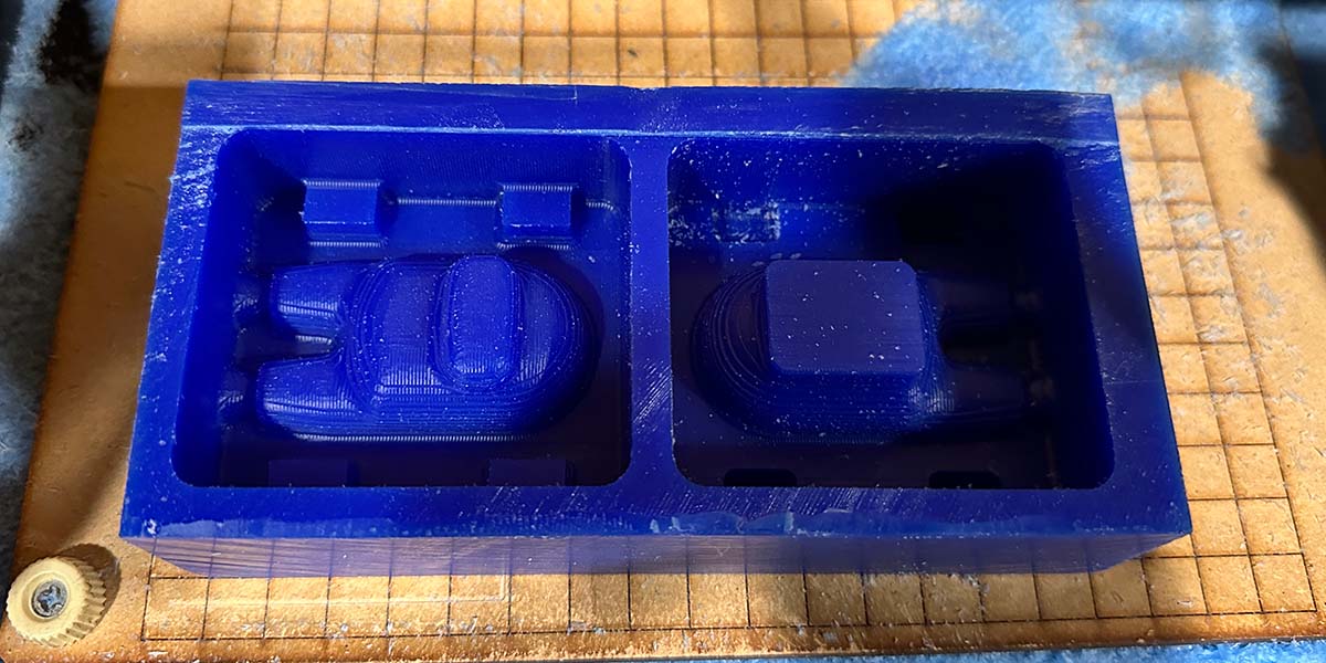
I used the same materials to make the silicone molds, and as you can see in the images, the lines are quite noticeable.
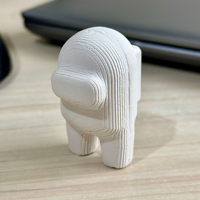
The result is as follows: I think it's quite good, although the lines are quite noticeable. Some bubbles also formed in the same area as in the previous test.

Download:
Here you can download de printable parts of the mechanical structure: