WEEK 10
Mechanical design, Machine design
Group Assignment:
- Design a machine that includes mechanism+actuation+automation+application
- Build the mechanical parts and operate it manually
- Document the group project and your individual contribution
- Actuate and automate your machine
- Document the group project and your individual contribution
This week was very enjoyable for me because we had to apply much of what we learned in previous weeks, and it also required a lot of research on the topics we wanted to learn about.
Group Assignment
This week, I worked with Naldi to develop the group project. You can find more information here.
MECHANICAL DESIGN
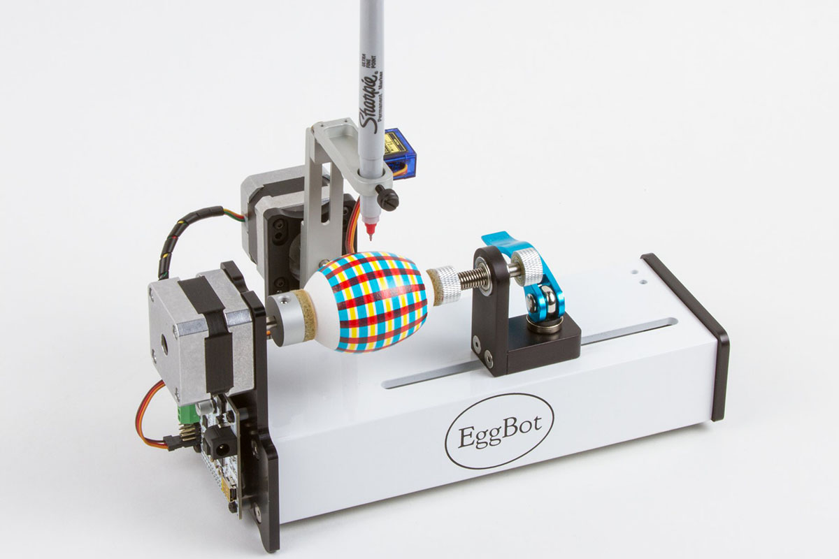
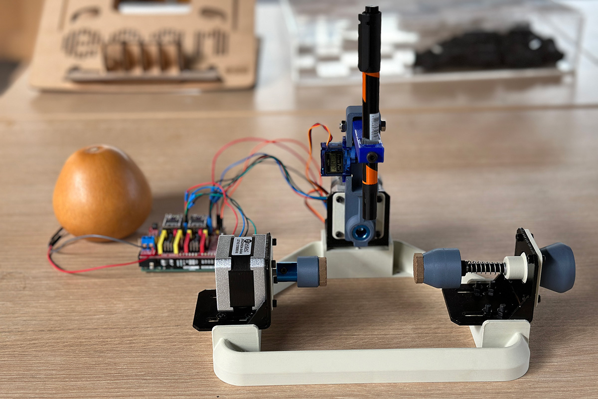
This is the final result our Carved Groud Bot. However, we have a few design iterations base on other projects that develop egg-drawing CNCs.
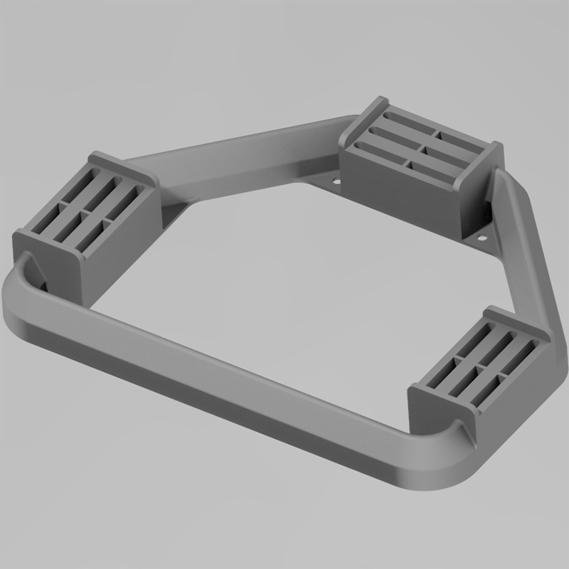
Taking the Sphere-O-Bot, as a reference, we develop a first design, following similar main frame. However we discarded this design due to:
- The main frame has horizontal holes to hold the safth, but the printing process requiered supports. This cause rough printing surface, which create problems with screws's alignment.
- Due to main frame dimensions the printing process was almost 4 hours, and this could become a problem during future iterations (include some improvements), and we had a constrained timeline.
We look for other possibilities, and base on The EggBot Pro, a commercial device that uses a solid aluminium main frame that is why we decided to use commercial brackets for the NEMA 17 stepper motors. This selection generate a design improvement.
We tested the mounting hole to the stepper motor. The figure on the left shows the original dimension that it was suppose to fit into the stepper motor shaft directly. However, it was not possible to couple the piece with the stepper motor's shaft. This because the stepper motor shaft did not have a notch that could provide a better adjustment. Thus, we change the mounting hole diameter (The figure on the right), in order to use a commercial Shaft Coupling (5-8mmx20mm). This product provides fixation holes that allows to fasten the shaft and the axis arm with set screws.
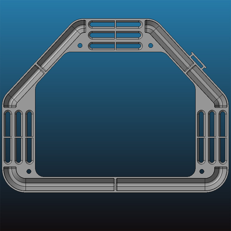
Main frame desing evolution:
- The Stepper motors and main frame mounting holes changed from horizontal to vertical position (figure on the left). This because we decided to use stepper motor commercial brackets. Thus, we could ensure fastening.
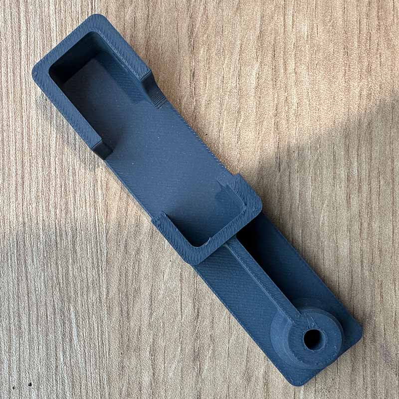
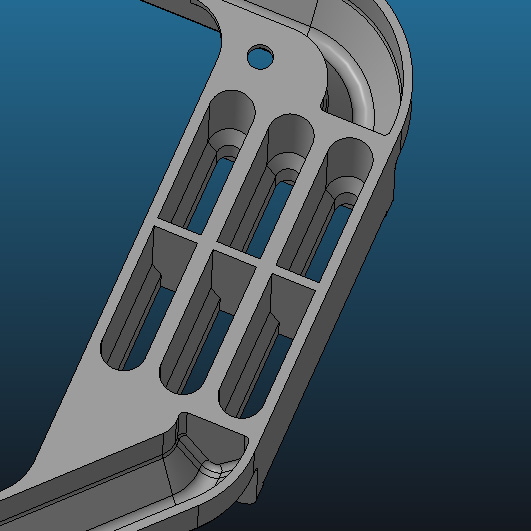
- Other advantage relies on reducing printing time, due to volume reduction and to turn a solid 3D printed geometry to a shelled model (figure on the right). We decide also to change the regular flat top surface to a 60° angled surface. This was to avoid the of supports in the printing process.
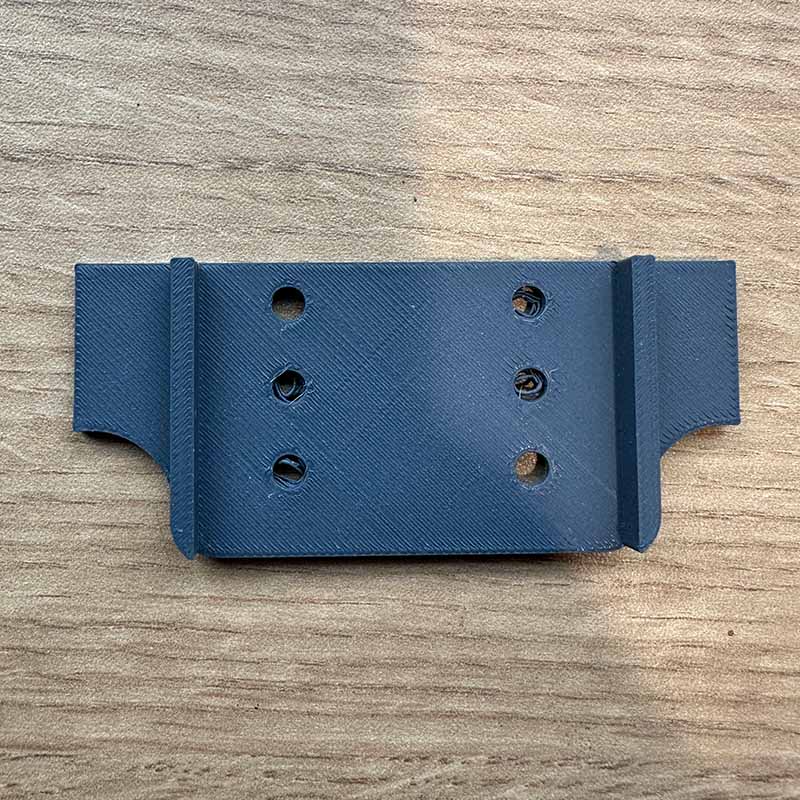
We also tested with different rows of holes for mounting the brackets to the main frame. However, this kind of adjustment hinders the assembling. Thus, the final design (figure on the left) changed to slots.
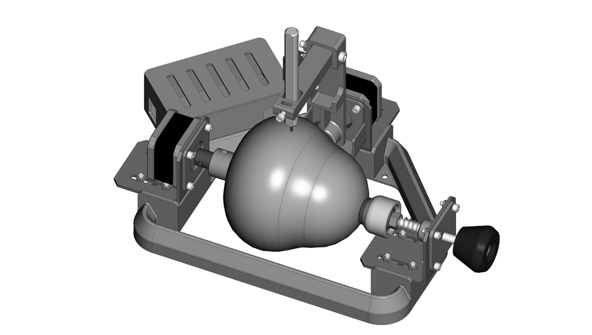
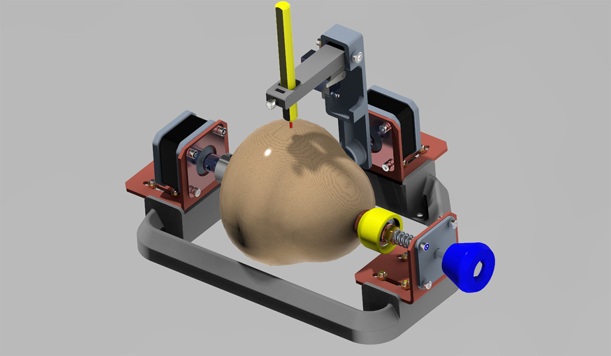
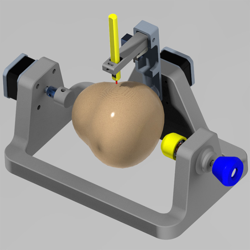
The final Mechanical design:
Once the components and mechanical design changes were done, we attempt a first assembly. Thus, we describe key mechanical parts:
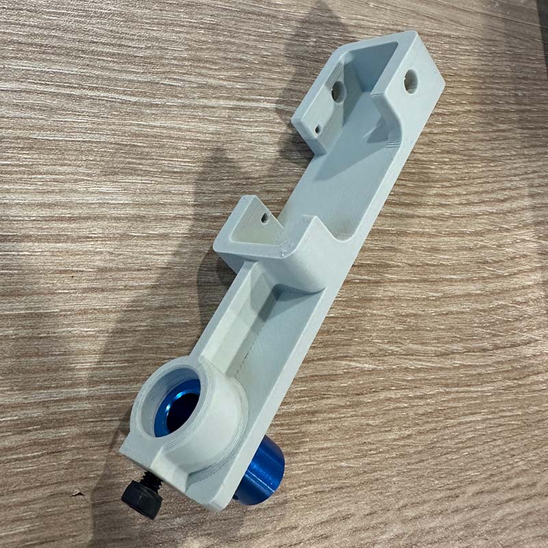
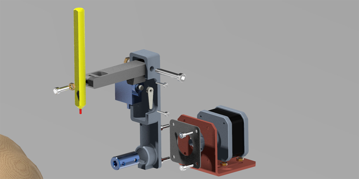
X Axis press and turn mechanism: This allows gourd adjustment. The design bring the possibility to increase gourd sizes from 8 to 10 cm. Also includes a 608 bearing, that facilitates rotation.
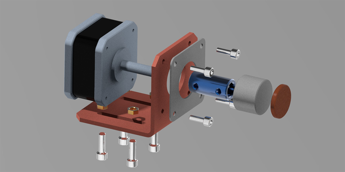
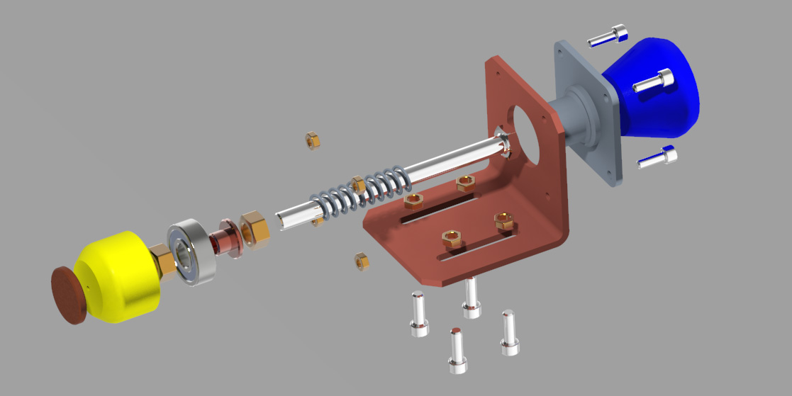
X Axis Actuator: This render shows assembles of the bracket to the main frame and the stepper motor to the bracket. Also, how the shaft coupling is adjusted and the inclusion of a holder-top. This final part receives the EVA circular sticky pads, that would sustain the gourd.
Y-Z Axes: This render shows assembles of the drawing arm.
The final mechanical desing explotion view:
THE ELECTRONIC ASSEMBLY
For this project we are using:
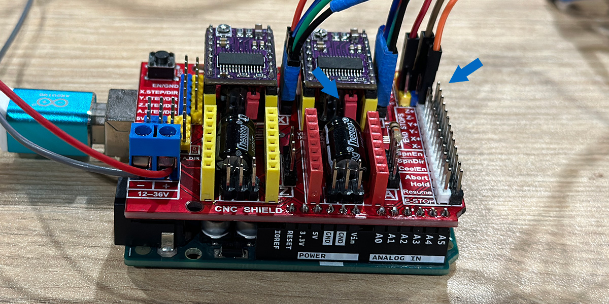
- A CNC-Shield V3 compatible with Arduno Uno. This is one of the most used to support CNC machines.
- We used DRV8825 stepper motor drivers. This device provides a maximun current of 2.5A and a allows 1/32 microstepping, that is very useful to work with CNC that will generate drawings, because it provides better resolution. We configurated both stepper motors driver to 1/16 microsteps, thus we included a jumper on MOODE2 (M2) pin
- Additionally, we followed Elliot Williams, hacking solution to control a servomotor for Z Axis function. Thus, we use Z+ Axis End Stop pin to connect the servomotor.
SET-UP
To control de CNC we are using 3 key programs:
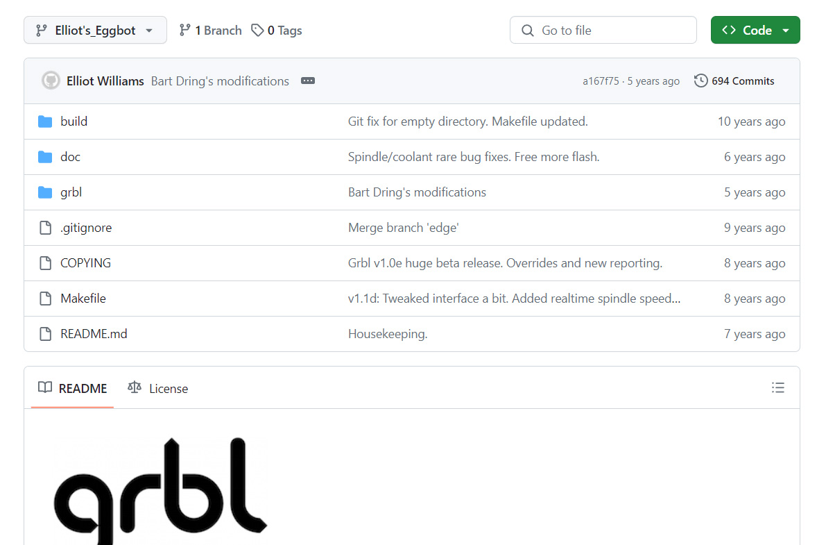
GRBL
We used GRBL with a variation elaborated by Elliot Williams. You can download the library here. You have to copy the grbl folder into the arduino libraries folder. Then we have to upload the grbl to Arduino Uno, we can find it at File> Examples> grbl> grblUpload after connecting the Arduino.
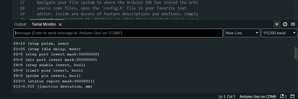
Then we need to test that the GRBL. So we need to open the Arduino serial monitor, then we need to select 115200 Bauds and select 'New Line'. You can test if everything runs ok by sending a $$ command, it will send you back the grbl parameters.
INKSCAPE
We used Inkscape because it has an extencion called GcodeTools which generate the g-code from the drawing.
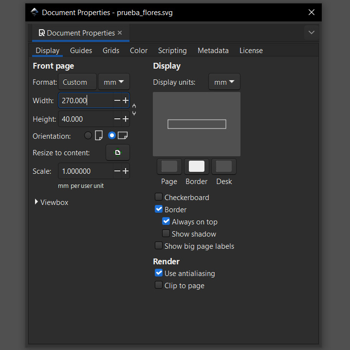
First we set up the graphic dimensions. Thus, We assumeed the gourd shape as a cylindrical geometry. So we measured the perimeter and height that we will be used to generate the drawing. We stablish a 270x40mm as work area. Then, we set the 270x40mm area into a new document properties.
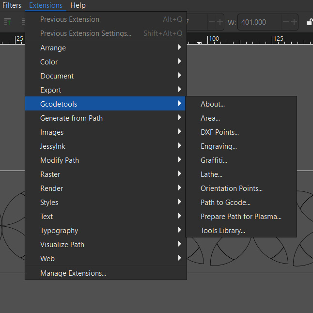
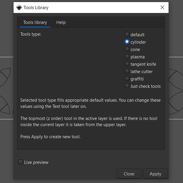
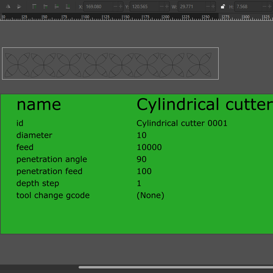
STEP 1: We had to select the tool type from Extensions> GcodeTools> Tools Library and selected cylinder, this process brings you the tool features (see the green box). Here it is recommendable to change the feed feature (it will appear with 400) to accelerate the movements.
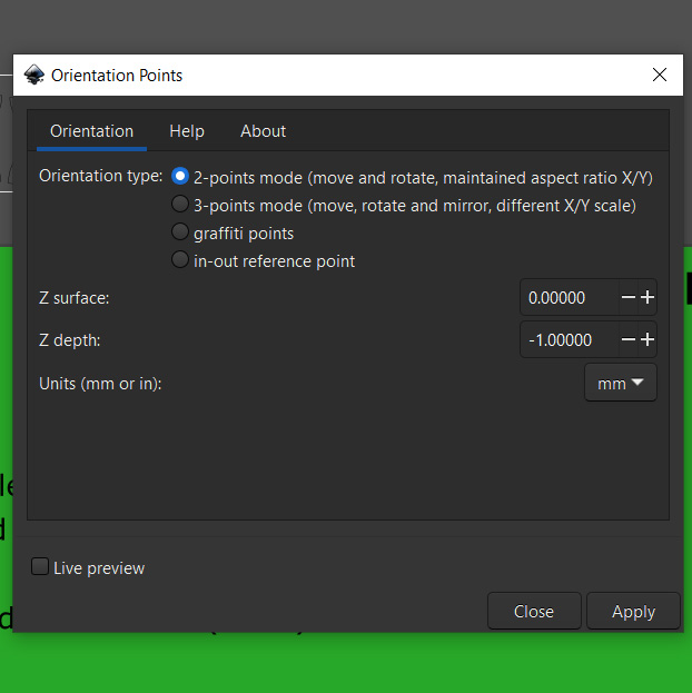
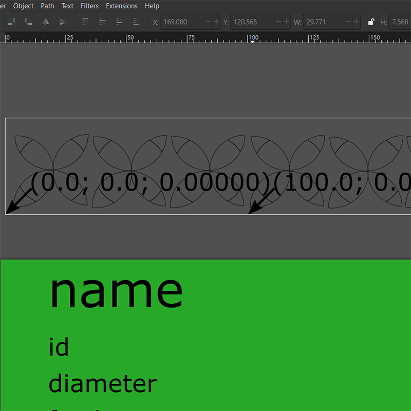
STEP 2: We had to add the XY coordinates origin from Extensions> GcodeTools> Orientation Points in this window we will maintain the default configuration, after click on apply, the orientation coordinates will appear in the bottom left of the drawing area.
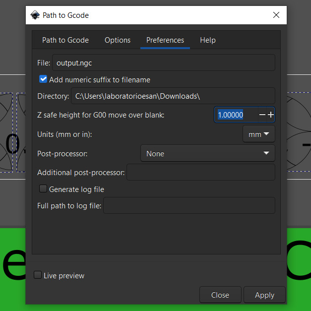
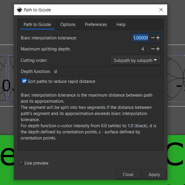
STEP 3: To generate the gcode ensure that the images are grouped, vectorized and selectes then, then we have to go toExtensions> GcodeTools> Path to Gcode in the preferences tap, we selectected the directory and the Z safe height (we selected 1mm insted of the default value of 5 mm), this value could afect the time of the painting proces. With the Path to Gcode tab activates, click on apply. After that a .ndg extension file will be created.
UNIVERSAL GCODE SENDER
This program connects the computer with Arduino Uno with GRBL.
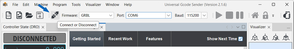
The UGS is available in GitHub, two options are available. The UGS classic and UGS Platform. In our case we use the last one because it runs without installation and includes java. Download the files and go to ugsplatfomr> bin> ugsplatform64.exe and execute the .exe, the connect it with the Arduino.
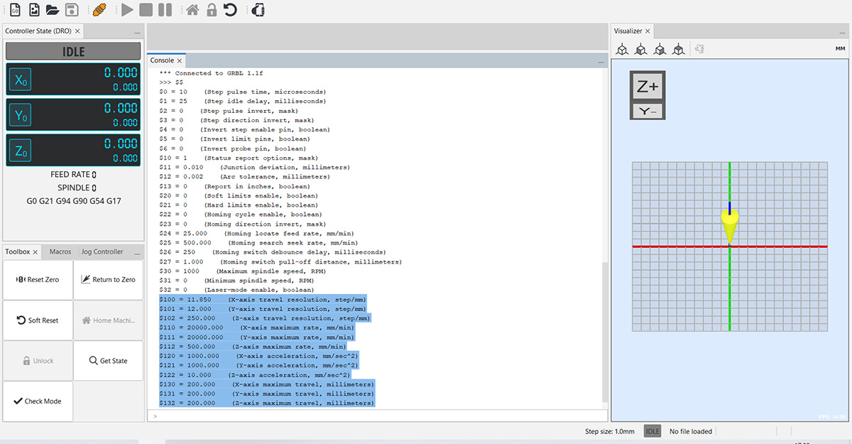
We need to configure the GRBL parameters. Thus, send $$ command. With that command the program will echo a list of parameters. Between those, we need to focus on the ones labelled as $100 to $132 parameters (see the following picture), but we changed only six (06) specific parameters.
- $100: X Axis Travel Resolution: 11.85 step/mm (We devided 3200 microsteps / 270mm)
- $101: Y Axis Travel Resolution: 12 step/mm (Our Y axis has 40° movement (480 microsteps to cover 40 mm length))
- $110: X Axis Maximum Rate: 20,000 mm/min (we test different velocities and set it more efficiently)
- $111: Y Axis Maximum Rate: 20,000 mm/min (we test different velocities and set it more efficiently)
- $120: X Axis acceleration: 1000 mm/sec2
- $121: Y Axis acceleration: 1000 mm/sec2
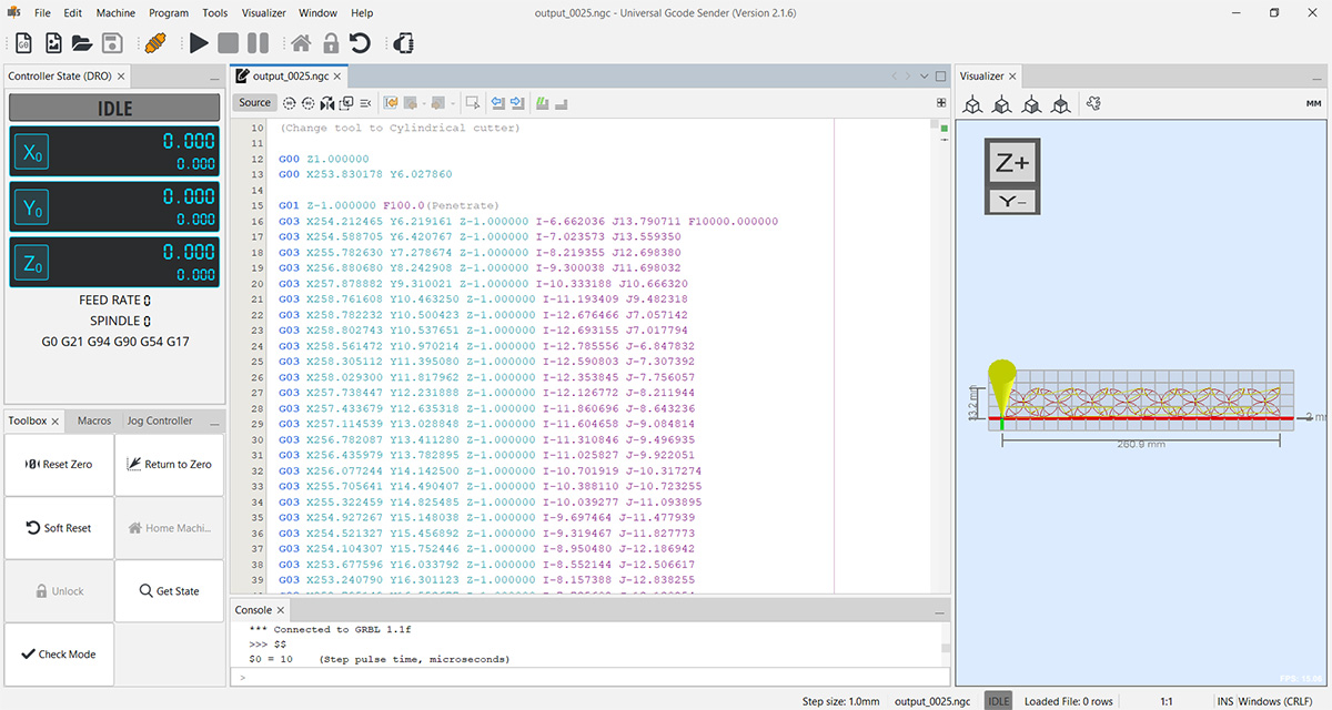
Then open the .ngc extension file created previously. To start drawing click play button. The CNC will start drawing, like shown down below.
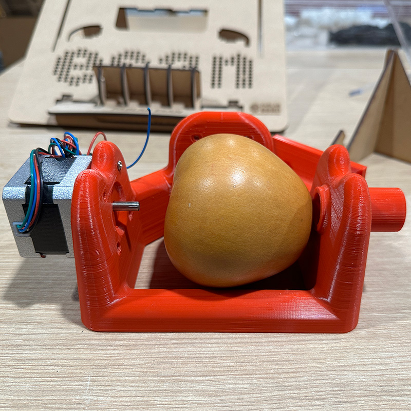
After assembling all the parts:
TESTS
We conducted several tests with the GRBL parameters. In the following video, we can observe the machine's behavior with an acceleration of 10 mm/sec^2 and a max rate of 500 mm/min, which are the default values. Additionally, we can see that the time between sections is around 3 seconds. This improved by reducing the Z safety distance when generating the gcode in Inkscape.
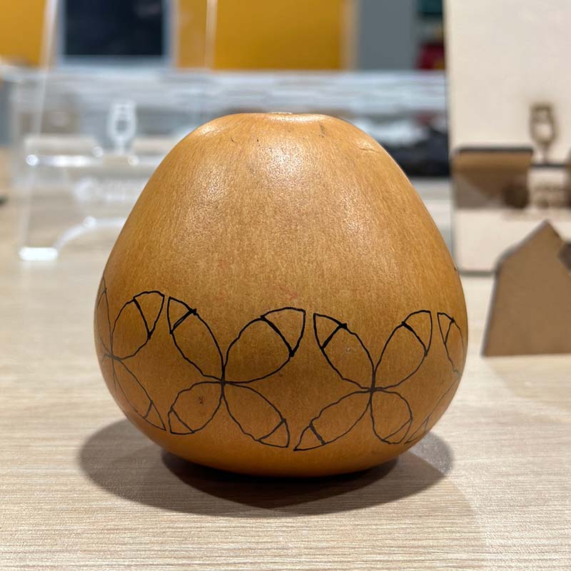
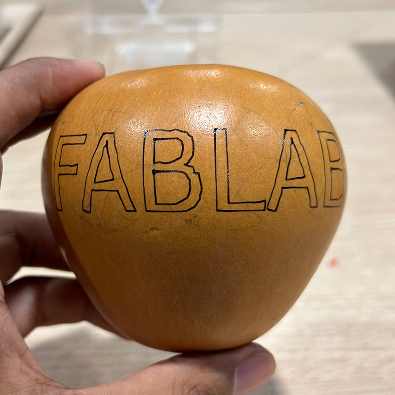
With the changes in the values of the GRBL parameters already implemented, we made the following designs: a kind of flowers, and the other drawing the text "FABLAB esan".
During testing, we also noticed that if the distance of the pen tip is adjusted, the dimensions of the drawing can change significantly. Also, in some cases, because the surface of the gourd is not symmetrical, the Z safety height is not sufficient, which could result in an unwanted line being drawn
The result of the two designs:
Download:
Here you can download de printable parts of the mechanical structure:
Download the version 2:
We implemented some improvements to the previous model, such as a case for the electronic components and support to limit the range of arm 1. We also plan to place a spring to cushion the fall of the pen.