In the previous page we looked over all my plans for my final project, but there is a big problem in it! I wanted my final project to be something that is easier to use and also a lot smaller than my previous design. For that I will have to completely change my design and way my project works!
I guess this will be my second spiral to completing my project. This time I will make sure that there are almost no flaws in my design with it also to make sure that it benefits all the people who might use it.
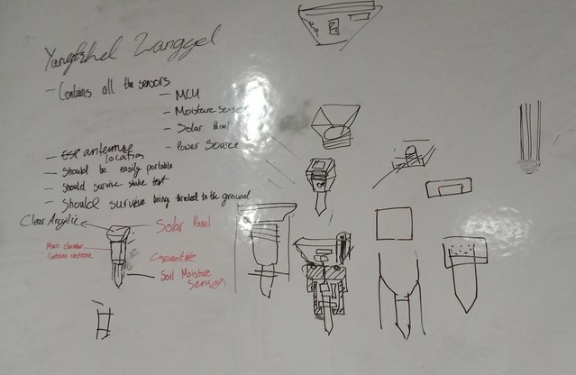
Sketch
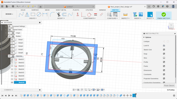
This is the renewed sketch of my final project! I want to make it as compact as possible and then also make it a bit more cooler compared to the heavy cylinder it used to be. I also took out a lot of the sensors that I thought would be irrelevant to my project as they either took too much space or were just too expansive to get!
The components that I will now be using are:
Capacitive soil moisture sensor
DHT11 humidity and temperature sensor
Solar panel
3.7 volts lithium ion battery
Xiao esp32 c3
WOW... I have made a lot of changes for my final project and I also haver very good reason for it.
First of all like I said before I removed some sensors from my final project as I not only wanted to keep my final project compact but also I wanted to reduce the overall cost of my project. I wanted to make it so that anyone can recreate my project with minimal expenses.
Secondly I also added a solar panel with a rechargeable battery so that I would not have to constantly change the batteries when ever my project ran out of fuel.
Also I removed the LCD screen. Now to display the readings given by my project, I (with the help of my fab guru "Rico Sir") decided on hosting a web sever and when people enter in the ip address they will be able to get all the readings that is being displayed by my project.
Actualization
With all of that planning, now next move on to actually make it all really and really start fabricating it.
Firstly I have to start with the fabrication of my micro controller board! Now I am using the xiao esp32 c3, instead of the attiny3216 micro controller. I have some great memories with the attiny3216 as it is the micro controller that carried through all the week of the fab academy but it has its limitations and I must accept them. Such as the fact that it does not have a wifi protocol which is required for my project. Also I need to change my encloser for my final project a bit as my previous design was quite big and not really portable!
With the reasoning done lets start with designing our new encloser and board!
Encloser
Firstly we have to create our encloser. It is very important to note that my encloser has to have some key features that need to be implemented:
1. Firstly I have to make my encloser water prove so that it stay outdoors even if it rains.
2. Secondly we also have to make it as small as it can possibly be. So that it can be portable and easy to recreate.
3. It should also include a place for the solar panel to be placed in and generate electricity for my project.(Basically meaning my design will have two components, one to hold all the other components and the other to hold the solar cell then also I must have both of these components join in away that it is still water prove!!!)
4. Also most importantly it should be able to survive the shake test😀.
Designing!!!
Now lets start designing our encloser and then get thing started with and than also tested. To design my encloser I will be using fusion 360! So without any interference, lets goo!
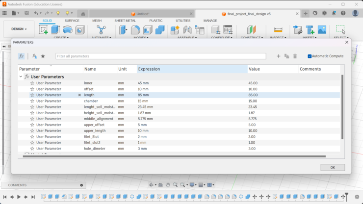
Before anything we always need to have all our parameters in check to ensure that even if you mess up in the future you can just fix it!
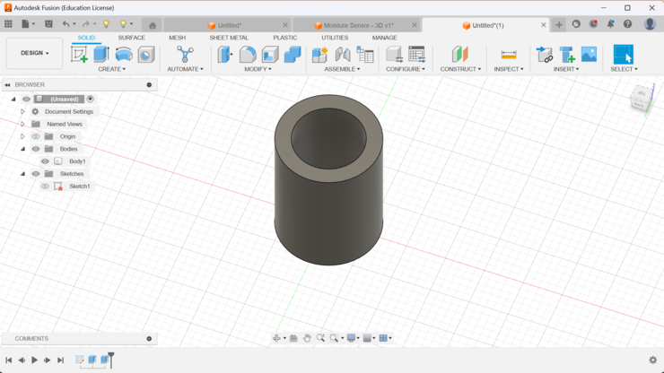
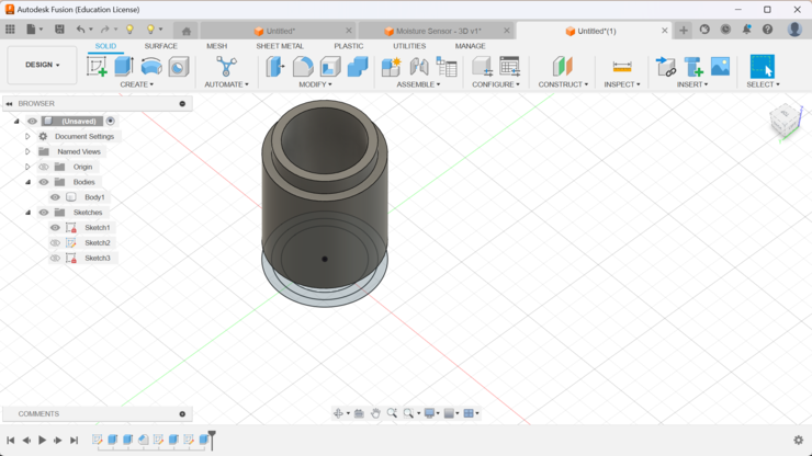
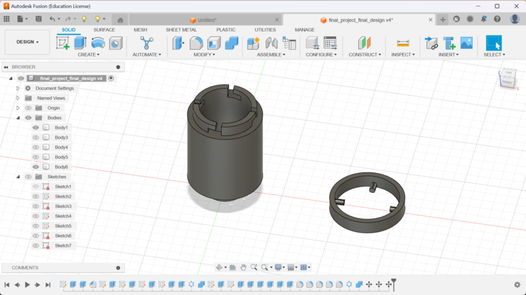
Next we just have to create a cylinder. for me I created a 45mm circle and then I just added an offset of 10mm. After that I just extruded the sketch.
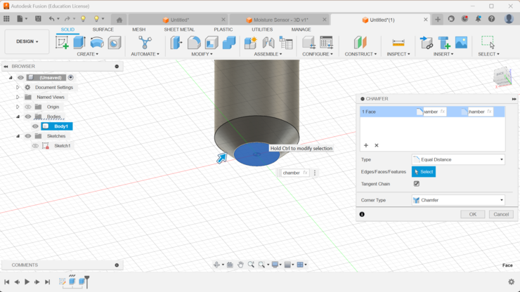
With that done next I made a chamfer at the bottom of the cylinder to act as a mount for the soil moisture sensor.
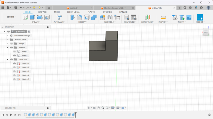
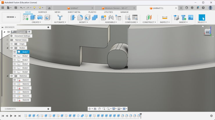
Now the hard part starts! we now have to make the mechanism that will be able to put together the two different components. To begin we must first create an extrusion on the top on the cylinder that we preciously created. What I want to create is a slide lock system on the top of the first component and then the other part of the lock will be placed on the component that holds the solar cell.(the socket will be on the main component while the header or pin of the lock will be on the component that holds the solar panel.)
Now to create a slide lock mechanism, I have to create it in two parts. Those two parts are the socket and the lock pins. I want to have the socket on the main body of the design while the lock pins will be on the component that holds the solar panel.
To create the socket I first created a this weird shape that had the height of the extrusion I created in the previous step. The width of the of the design has to be a bit more than the offset(for me it was +15mm). Then I had the design extrude to the side(the distance extruded is equivalent to the length of the lock pin.)
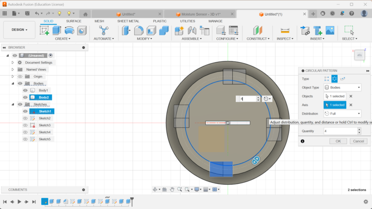
With the weird shape created we can simply just create a circular pattern with the shape as the object and the original circle as the axis it is going to move on! Remember to keep the operation as cut! if you don't want to end up with a really weird shape!!!
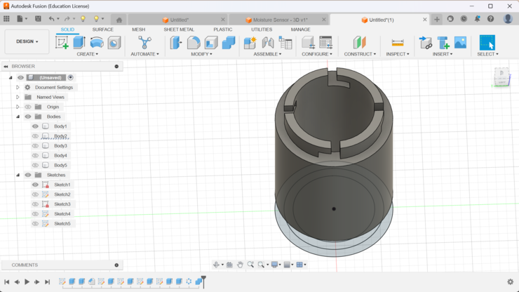
As we are now done with creating the pattern and then also cutting the main component according to the to lock pin, we are now done with the socket!!!
To create the socket I simply just extruded a sketch and then adjusted it to the pin in the socket(NOTE: I also added filets so that it would not have as much tolerance as it would have, if it was a square.)
After I created the key I then just used the pattern tool to create the same lock pin to all the sockets and then attached it to another platform(NOTE: this platform is going to be the platform that is going to contain the solar panel ).
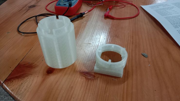
I need to confirm if whether the slide lock actually works so, I for that I printed just the slide lock components of the encloser. This way I will be wasting 2 hours of my life instead of wasting like 12-16 hours of my life 3D printing if my slide lock fails!
I just started up my printer and then begun with the printing process. The print took around 2 hours and 10 minutes. This is how it looks after it was done printing!
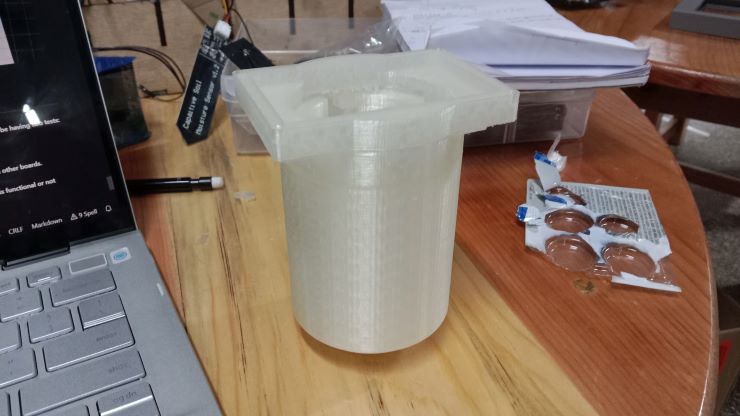
When the printing finished, I just tested if the slide lock works or not and it did!!. Next I had to make sure if whether the lock was tight enough to not let water pass. To do that I covered the two ends and then poured water on the place on joint.
After the test was over, I was really surprised!!! I thought that for the joint to be water prove, I required some sort of rubber to go between the joints but apparently I didn't need then as the joints are water prove as it is now!
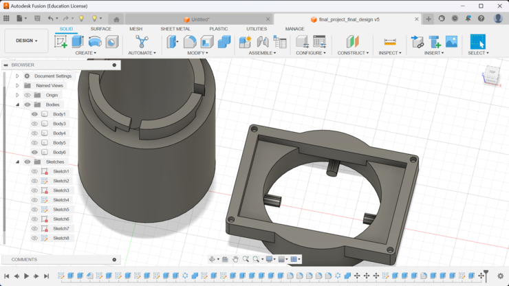
With that reassurance all I have to do is to create the platform for the solar panel on the lock pins. I just put in the dimensions of the solar panel and then had an offset of 5mm.
After that we just extruded the sketch. And also filled up the gaps with an offset with 5mm.
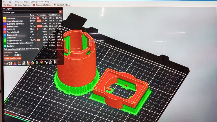
This is how it looks in Pursa Slicer.
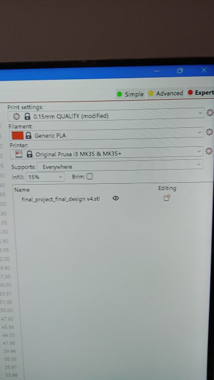
and if you are wondering these are the print setting on which I printed.
After printing
For more on the system integration please visit my final project. -->
Speacial Thanks To
Anith Ghalley : my local instructor, his website helped a lot while creating this site!!
Rico Sir As our fab guru his experince and knowledge that he shared to us was very important, and also his website was a good reference
My friends: My friends are the people who helped most while creating this site!!