Week 13: Communication and Networking😋!
(This is the week!), I have never ever in my life, had the experience of communicating between two or more devices🥶! I truly am poking my nose in the world of the unknown this week and I dearly hope I enjoy it! Getting in to the main context of this week. We have to communicate with two or more micro controllers. Additionally we also have to communicate with our board through the use of wireless communication, whether it be wifi, lan or bluetooth. (All of that sounds way to complex!...💀).
also, this week we are back at it again with the electronics! The break away from electronics provided the molding and casting week was sure a great time off, but I can confidently say that I surely did miss electronics. Hopefully I haven't become rusty and not able to do electronics! With that lets no get into the assignments.
Assignments
I already mentioned a little about this weeks assignments. But now I intend to clearly mention all the assignment I will be doing this week.
design, build and connect wired or wireless node(s) with network or bus addresses and a local interface
Group Assignment🤩
The group assignment as well includes communication as everything this week.
Send a message between two projects
Document your work to the group work page and reflect on your individual page what you learned.
For this weeks group assignment we had to communicate between two projects. To do that we used two esp32 c3 xiao boards from a connection between them so that we can use the wireless communication feature on the esp32 c3 xioa board to wirelessly communicate between the two of them. I personally learned a lot on how I would be able to write the code for TCP communication between xiao boards, I also was able to learn of how to program in a way to create a web sever
Reflection
This weeks group assignment was tough! But through this was I able to learn a lot fomr this. I myself was tasked with the programming bit of the assignment and boy, was it tough! I could feel myself really being worried about how I might complete this. Though in the end I was able to pull it off. It was my first time connecting a micro controller to wifi and then making it connect with another to send messages, but it was all worth it in the end!
Now with all the assignments clarified we can finally start with all of our assignment and work for this week.
Understanding🧐!
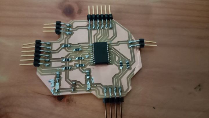
This is the Data sheet I got for this module HC-05
For this week we have to communicate with two or more board through either wired or wireless communication. Knowing me I am using the attiny 3216 micro controller as the main micro chip for my final project board. I have a problem with that, the attiny 3216 doesn't have a default wireless communication protocol in built in it. That means that I have to find a wireless communication module that I can connect with my board so that I can be able to communicate with it wirelessly.
Facing with such a problem, I had to think quickly on how to connect a wireless communication module to my board or if I could find any alternative solution to wireless communication.
After a while of digging and searching through out the internet, I found this module.
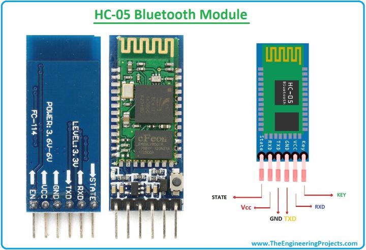
The HC-05 Bluetooth module is a widely used module in electronic projects and IoT applications. It is a versatile module that allows devices to establish wireless connections and communicate over short distances. The module operates based on the Bluetooth technology, which utilizes radio waves to enable communication between devices without the need for cables. Bluetooth operates in the 2.4 gigahertz frequency range and supports various profiles and protocols for specific functionalities. The HC-05 module, in particular, acts as a Bluetooth serial port, providing a convenient means for devices without built-in Bluetooth capabilities to connect and exchange data with other Bluetooth-enabled devices. It is compatible with the Serial Port Profile (SPP), making it suitable for a wide range of devices and programming languages. The HC-05 module is commonly used in projects such as home automation, robotics, and wireless sensors, offering a reliable and convenient wireless communication solution.
I really need to thank the one who came up with this module as with the help of this I can do wireless communication with out needing to create an entirely new board! (hooray🤩!!!)
As you saw from the above picture, the module has a total of 6 pins, but for my usage, I only require 4 of the above pins. Those pins are.
Tx pin - The tx pin on the module is necessary for communication between the board and the module.
RX pin - this pin, similar to the RX pin is necessary for communication between the board and the module.
VCC - this pin is pretty self explanatory. It is required to power the module. (NOTE: the module requires around 3.3V to 6V, due to a inbuild voltage regulator. For pair it requires more curretn about 30amphs and 10 amphs are being connected.)
GND - the ground pin has to be connected to ensure that the circuit is completed.
With a simple pin configuration, I am eagerly waiting to connect this to my board and start with communicate between my board and my phone through bluetooth.
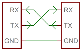
And also to mention always to remember to connect the TX of the module to the RX of the board, and vice versa.(This is important because I remember suffering big time due to this simple error in one of the previous weeks😭.)
Connecting
Before I try it on my micro controller, I had to first ensure the validity of both my code and my connections. For that I want to first test all my codes and connections on the arduino uno board before I upgrade onto my own attiny 3216 board!
I first connected the arduino board to my bluetooth module and then I simply uploaded the code for me to be able to control the bluetooth module.
To do this, I referred this documentation on the arduino project hub. Bluetooth module. This was a great module that had included everything that was needed to use the HC - 05 bluetooth module.
PIC - Fritzing
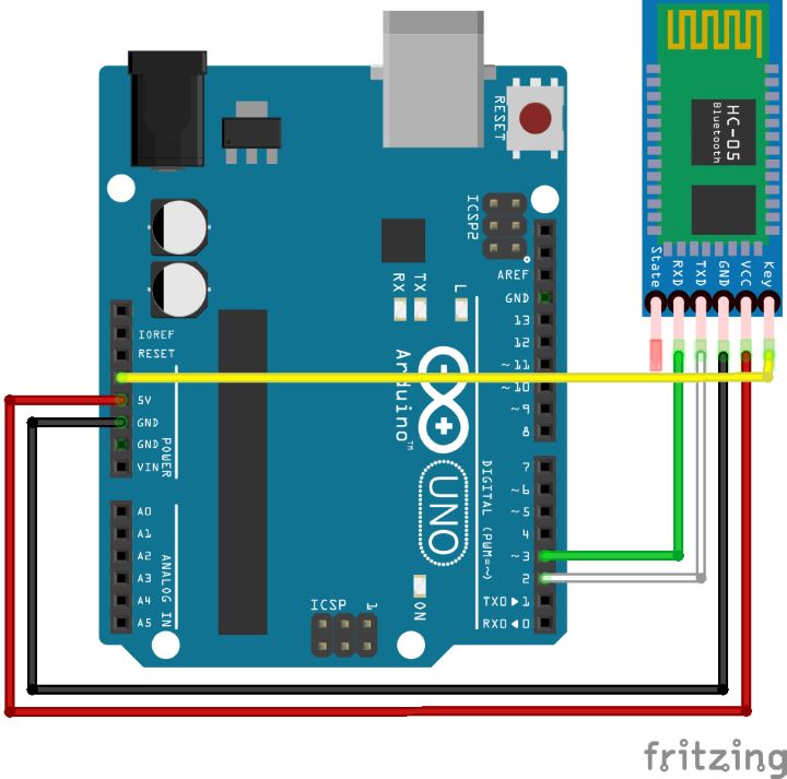
For the connections, I didn't connect two pins. The state and key pins! There are reasons for why I didn't connect these two keys is. The state key will send a voltage of 3.3v if the module is connected to bluetooth. Through this we can see if the module is connected or not. I didn't need this I didnt need to indentify to whether the module is connected or not. Next I didnt connect the key pin as the it activates the command mode in the module for me to be able to change it settings. That is also somthing that I really didnt need therefore I didnt connect it.
After all the connections were done I uploaded the code that was given in the documentation.
char Incoming_value = 0;
void setup() {
  // put your setup code  here, to run once:
Serial.begin(9600);
pinMode(13,OUTPUT);
}

void  loop() {
  // put your main code here, to run repeatedly:
  if (Serial.available()  > 0)
    {
      Incoming_value = Serial.read();
      Serial.print(Incoming_value);
      Serial.print("/n");
      if (Incoming_value == '1')
        digitalWrite(13,HIGH);
      else if(Incoming_value == '0')
        digitalWrite(13,LOW);
    }
}
After I uploaded this code to the arduino I could finally start sending messages to the board through bluetooth!
But I now have a problem. I have now way to communicate through bluetooth😰!!! to communicate with the bluetooth module, I first have to connect to the module and then have a sort of commanding interface such as a terminal. I searched through the internet and then found 2 apps that might just work to connect with the module
After I had to learn how to use the apps so that I would be able to send messages to the module.
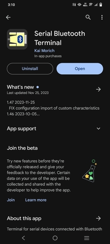
Serial bluetooth
As soon as you open up this app, you will be met with the opening page.
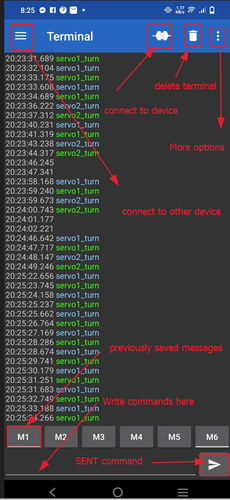
this app provides us a terminal so that we would be able to send commands to the bluetooth module. through this app you would also be able to customize ready made messages as well. you can make these ready messages by simply sending pressing the buttons write above the place where you write your codes.
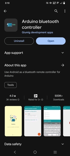
arduino bluetooth controller
This app also provides me a way for me to communicate with my bluetooth module. Though this app also 2 extra interfaces that provide different interfaces to communicate with the device.
After opening the app you have to pair up with the HC - 05 module and then when you are connected to the module this is the page that will show up.
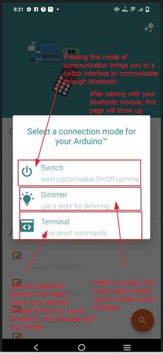
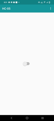
Firstly the let's see the button option.
When you press the button option, it takes you to a page with a button. the button has 2 states, its either on or off. Each of these states can be made to sent different values to the bluetooth module. you can also change the values the different states of the button will sent.
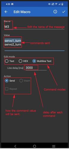
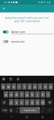
To change the values of the button states you have to press the three button icon and then you will be transported to this page.
Now lets get to the slider option of the app. The slider has its most prominent use as a sort of dimmer for LED control. This is because when the dimmer sends values back, the values could be used to control a LED to dim or brighten through a PWM pin.
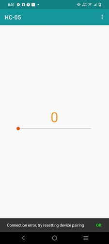
And like the button the option there is also ways you can change the values that are givin by the slider.
Final testing!
The code I previously gave wasn't really able to display much as it only used the built in LED.
Therefore I changed the code so that it would be able to have a dimming effect on two LED.
char Incoming_value = 0;  // Variable to store the incoming data

void setup() {
  Serial.begin(9600);             // Initialize serial communication at 9600 bits per second
  pinMode(13, OUTPUT);            // Set pin 13 as an OUTPUT for LED
}

void loop() {
  // Check if data has been received via Bluetooth
  if (Serial.available() > 0) {
    Incoming_value = Serial.read();  // Read the incoming data
    Serial.print(Incoming_value);    // Print the incoming data for debugging
    Serial.print("\n");

    // Map the incoming values (0 to 4) to PWM values (0 to 255)
    int pwmValue = map(Incoming_value - '0', 0, 4, 0, 255);

    // Set the brightness of the LED
    analogWrite(13, pwmValue);
  }
}
Hero shot!!
Hero Shot with my board!!!
After that I moved onto my own and hoped that all would go smoothly as it did with the arduino!
After I just set up my board it worked greatly!!!.
After that I tried controlling 2 servos through the use of the bluetooth module. For that I created a similar code that would use the value it gets, (example - servo1_turn) to turn the specific servo motor.
#include <Servo.h>

Servo servo1;  // Create a servo object for the first servo
Servo servo2;  // Create a servo object for the second servo

int position1 = 0;  // Initial position for servo1
int position2 = 0;  // Initial position for servo2

void setup() {
  Serial.begin(9600);             // Initialize serial communication at 9600 bits per second
  servo1.attach(9);               // Attach the first servo to pin 9
  servo2.attach(10);              // Attach the second servo to pin 10
}

void loop() {
  if (Serial.available() > 0) {
    String Incoming_value = Serial.readString();  // Read the incoming data as a string
    Incoming_value.trim();  // Remove any whitespace or newline characters

    Serial.println(Incoming_value);  // Print the incoming data for debugging

    if (Incoming_value == "servo1_turn") {
      // Toggle position between 0 and 180 degrees
      position1 = position1 == 0 ? 180 : 0;
      servo1.write(position1);  // Set the position of servo1
    } else if (Incoming_value == "servo2_turn") {
      // Toggle position between 0 and 180 degrees
      position2 = position2 == 0 ? 180 : 0;
      servo2.write(position2);  // Set the position of servo2
    }
  }
}
Unlike the previous which was really simple to create as it only required contrlling the brightness of a LED, the above code was somthing that I just wasnt able to do, and with time running out I had no choice but to use chat gpt. when I asked to tr yand create me the code to control 2 servos through the use of a bluetooth module, it gave me a code that was able to spin the servo motors through the use of the bluetooth module.
I2C communication!!!
In this week, we will explore how to utilize the I2C (Inter-Integrated Circuit) serial bus addressing to independently control an LCD (Liquid Crystal Display) and an OLED (Organic Light-Emitting Diode) display using the same set of I2C pins. By assigning unique addresses to each display, we can establish a networked communication system that enables simultaneous control and display of different content on each device. This documentation serves as a guide to implementing this networking and communication setup.
Advantages of I2C comunication.
Simplicity and Wire Efficiency: I2C offers a simple and efficient communication solution by using only two wires, SDA (Serial Data Line) and SCL (Serial Clock Line), irrespective of the number of devices on the bus. This simplicity reduces the complexity of circuit design, minimizes the number of connectors and traces on a PCB (Printed Circuit Board), and results in cost savings and compact system designs.
Multi-Master and Multi-Slave Configuration: I2C supports multi-master and multi-slave configurations, allowing multiple master devices to communicate with multiple slave devices on the same bus. This flexibility enables the implementation of distributed processing architectures, where multiple microcontrollers, sensors, and other peripherals can seamlessly exchange data. It facilitates parallel communication channels and real-time data exchange within complex embedded systems.
Addressing Scheme: I2C incorporates a built-in addressing scheme, enabling direct communication between the master and the designated slave devices without requiring additional wires for device selection. Each I2C device has a unique address, typically 7 or 10 bits long, allowing efficient data routing and eliminating the need for manual configuration or external decoding logic. The addressing scheme supports up to 128 (7-bit addressing) or 1024 (10-bit addressing) devices on a single bus.
Speed Modes: I2C supports different speed modes to accommodate a wide range of devices and applications. The standard mode (up to 100K bits per second) suits slower peripherals and low-power components. Fast mode (up to 400K bits per second) enables faster data transfer, making it suitable for intermediate-speed devices. High-speed mode (up to 3.4Mbits per second) caters to high-performance applications that demand quick data exchange between devices. The selection of the appropriate speed mode depends on the specific requirements of the system.
Synchronous Communication: I2C is a synchronous communication protocol, meaning it relies on a clock signal to synchronize data transfer between devices. The master device generates the clock signal, ensuring precise timing coordination. This synchronization allows for reliable and accurate data transmission, critical in applications where data integrity is paramount. The synchronous nature of I2C simplifies the design of communication interfaces and facilitates error detection and correction.
The above point have brought from this site here --> Link
Lastly we had to haev to maek the connections for the I2C communication.
Hardware Connection:
Connect the SDA (Serial Data Line) and SCL (Serial Clock Line) pins of both the LCD and OLED displays to the corresponding SDA and SCL pins on the microcontroller.
Ensure proper power supply connections for both displays.
I2C Serial Bus Addressing:
Each I2C device requires a unique address to differentiate it from other devices on the bus.
To know the addresses of both the LCD and the OLED I used the I2C scanner code from the original arduino page - Arduino
#include <Wire.h>

void setup() {
  Wire.begin();

  Serial.begin(9600);
  while (!Serial);

  Serial.println("\nI2C Scanner");
}

void loop() {
  byte error, address;
  int deviceCount = 0;

  Serial.println("Scanning...");

  for (address = 1; address < 127; address++) {
    Wire.beginTransmission(address);
    error = Wire.endTransmission();

    if (error == 0) {
      Serial.print("Device found at address 0x");
      if (address < 16) {
        Serial.print("0");
      }
      Serial.print(address, HEX);
      Serial.println();
      deviceCount++;
    }
    else if (error == 4) {
      Serial.print("Unknown error at address 0x");
      if (address < 16) {
        Serial.print("0");
      }
      Serial.println(address, HEX);
    }
  }

  if (deviceCount == 0) {
    Serial.println("No I2C devices found.");
  }
  else {
    Serial.println("Scan complete.");
  }

  delay(5000); // Delay 5 seconds before scanning again
}
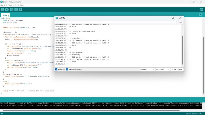
After uploading the code I simply turned onn my serial monitor and then all I had to do was open up my serial monitor.
After viewing the serial monitor, it worked. now all I had to so was so simply remember the bus address and then implement it in my next code so that I would be able to control them separately.
Next I had to write the code to control both the LCD and the OLED separately. In my code I imagined being able to write something on serial monitor and then it simply appears on the display. Also have the display done alternatively by both displays so that I can display different messages on both the displays.
#include <Wire.h>
#include <Adafruit_GFX.h>
#include <Adafruit_SSD1306.h>
#include <LiquidCrystal_I2C.h>

#define OLED_SDA 4      // OLED SDA pin connected to Arduino digital pin 4
#define OLED_SCL 5      // OLED SCL pin connected to Arduino digital pin 5
#define OLED_ADDRESS 0x3C  // OLED I2C address

#define LCD_ADDRESS 0x27  // I2C address of the LCD display

#define LCD_COLS 20     // Number of LCD columns
#define LCD_ROWS 2      // Number of LCD rows

// Declaration for SSD1306 OLED display connected to I2C
Adafruit_SSD1306 oledDisplay(128, 64, &Wire, OLED_ADDRESS);
// Declaration for I2C LCD display
LiquidCrystal_I2C lcdDisplay(LCD_ADDRESS, LCD_COLS, LCD_ROWS);

void setup() {
  oledDisplay.begin(SSD1306_SWITCHCAPVCC, OLED_ADDRESS);
  lcdDisplay.begin(LCD_COLS, LCD_ROWS);

  oledDisplay.clearDisplay();
  oledDisplay.setTextSize(1);
  oledDisplay.setTextColor(SSD1306_WHITE);
  oledDisplay.setCursor(0, 0);
  oledDisplay.println("Hello, OLED!");

  lcdDisplay.clear();
  lcdDisplay.setCursor(0, 0);
  lcdDisplay.print("Hello, LCD!");

  oledDisplay.display();
}

void loop() {
  oledDisplay.clearDisplay();
  oledDisplay.setTextSize(1);
  oledDisplay.setTextColor(SSD1306_WHITE);
  oledDisplay.setCursor(0, 0);
  oledDisplay.println("Hello, OLED!");

  lcdDisplay.clear();
  lcdDisplay.setCursor(0, 0);
  lcdDisplay.print("Hello, LCD!");

  oledDisplay.display();
  delay(2000); // Delay for 2 seconds

  oledDisplay.clearDisplay();
  oledDisplay.setTextSize(1);
  oledDisplay.setTextColor(SSD1306_WHITE);
  oledDisplay.setCursor(0, 0);
  oledDisplay.println("This is OLED!");

  lcdDisplay.clear();
  lcdDisplay.setCursor(0, 0);
  lcdDisplay.print("This is LCD!");

  oledDisplay.display();
  delay(2000); // Delay for 2 seconds
}


#include <Wire.h>
#include <Adafruit_GFX.h>
#include <Adafruit_SSD1306.h>
#include <LiquidCrystal_I2C.h>

#define OLED_ADDRESS 0x3C
#define LCD_ADDRESS 0x27
#define LCD_COLS 20
#define LCD_ROWS 2

Adafruit_SSD1306 oledDisplay(128, 64);
LiquidCrystal_I2C lcdDisplay(LCD_ADDRESS, LCD_COLS, LCD_ROWS);

String inputString = "";      // a String to hold incoming data
bool stringComplete = false;  // whether the string is complete
bool displayOnOLED = true;    // toggle between OLED and LCD

void setup() {
  Serial.begin(9600);
  Wire.begin();  // Initialize the I2C communication
  oledDisplay.begin(SSD1306_SWITCHCAPVCC, OLED_ADDRESS);
  lcdDisplay.init();  // Initialize the LCD display
  lcdDisplay.backlight();  // Turn on the backlight for the LCD
}

void loop() {
  if (stringComplete) {
    if (displayOnOLED) {
      // Display on OLED
      oledDisplay.clearDisplay();
      oledDisplay.setTextSize(1);
      oledDisplay.setTextColor(SSD1306_WHITE);
      oledDisplay.setCursor(0, 0);
      oledDisplay.println(inputString);
      oledDisplay.display();
      displayOnOLED = false; // Toggle to LCD for next input
    } else {
      // Display on LCD
      lcdDisplay.clear();
      lcdDisplay.setCursor(0, 0);
      lcdDisplay.print(inputString);
      displayOnOLED = true; // Toggle back to OLED for next input
    }
    // Clear the string for new input
    inputString = "";
    stringComplete = false;
  }
}

void serialEvent() {
  while (Serial.available()) {
    char inChar = (char)Serial.read();
    inputString += inChar;
    if (inChar == '\n') {
      stringComplete = true;
    }
  }
}
The above code was an even bigger problem compared to the last one, I really struggled to do this. But my local instructor and ai really did help me. Firstly my instructor help to create a code that was able to toggle between the OLED and then the LCD so that messages would be between the both of them. Next I ask Chat GPT to make the code for the serial bus as I didnt know that you had to create a variable to fit address for both the OLED and then the LCD. But after that was done, the rest was a piece of cake.
Big thanks to my instructor, Mr Anith Ghalley, he really help in this entire process and also he help me with this code when I was having a errors running it.
With that all I had to do was upload this to my board.
Hero shots? or Hero Videos
Hero Shot of my board