Week 7: Computer Controlled Machining🤖
Welcome to the seventh week of the Fab Academy! This week is all about computer-controlled machining.
You'll learn about different types of CNC machines and their applications. You'll also acquire hands-on experience in operating CNC machines and understand the safety protocols associated with them.
You'll also delve into the process of designing for machining – from creating CAD models to generating machine code using CAM software. At the end of this week, you'll be able to transform your digital design into a physical object using a CNC machine. Let's get started! We were asked to create somthing big! for this week and thats is excatly what I intent to doo.
Neils Lecture
Neil Sir's lecture this week was truly incredible. His insightful explanations and comprehensive overview of computer-controlled machining provided a solid foundation for understanding the topic. His ability to make complex concepts easily understandable made this learning experience extremely enriching and engaging. He also showed his concern for everyone by ensuring that we wont by pass any safty measure. He also informed how the cnc machine was the second most risky machine to use in the lab.
Assignments!!🤩
For This week we had Create somthing big with the use of the cnc machine!! I am going to create somthing that is useful as since we are tasked with creating somthing big. Since we are creating somthing that is big why not make it useful so that the material aren’t going to be wasted!
Create somthing Big!! - Create somthing on the metric scale.😀
Objective - Create somthing that is useful so that material arent going to be wasted.
Software - Fusion as I am more comfortable doing parametric design in this software. I have to make a simulation to make sure that the fits are accurate.
Group Assignment!😋
To go to our group assignment, Press here --> GROUP ASSIGNMENT.
In this assignment, we aim to explore the capabilities of the ShopBot PRS standard CNC machine, a powerful and versatile platform for computer-controlled machining. We will learn about the machine's specifications, understand its safety rules, and then model and cut a simple object.
I myself was really having fun using the machine to cut wood and to know of its limitations.
The machine we are using is the Shop Bot CNC PR standard for this week.
With it we will be using the 6 mm mill bit with 2 clockwise flutes.
Also with the group assignment I now know that for good profile cut, our machine spindle goes through a RPM of 10000 rotations per minute.
For our design we used 2 tabs and a material of wood with an thickness of 15cm and a simple design to check out the main accuracy for our machine.
Now that we have gone through all action that we going to go through, Lets now officially begin the 7th week of the fab academy!🤪
3D modelling🗿
I am going to create a 3D model of the design I want to cut using the cnc just to ensure that I dont make any errors that could ruin the entire design! I will also make a breif simulation of my model so further ensure that my design doesn't have any errors.
Firstly to start off, my design is going to mostly have the pressfit joint as the main joint for this design as,not only is this joint simple to create but also is really sturdy😼
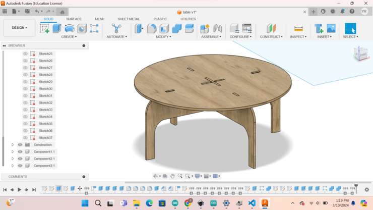
With that now lets begin designning!Ohh I almost forgot to mention what I will actually be creating!😅. For this week we have to create somthing big and useful, cause of that I thought "why not create a simple table?". A tabel for say can be useful for various different purposes.
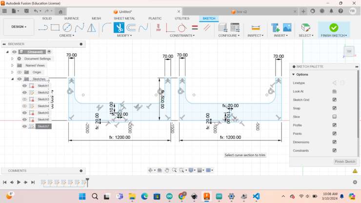
Firstly lets get into all the parameters that I used to create this design of my cnc table🤩.
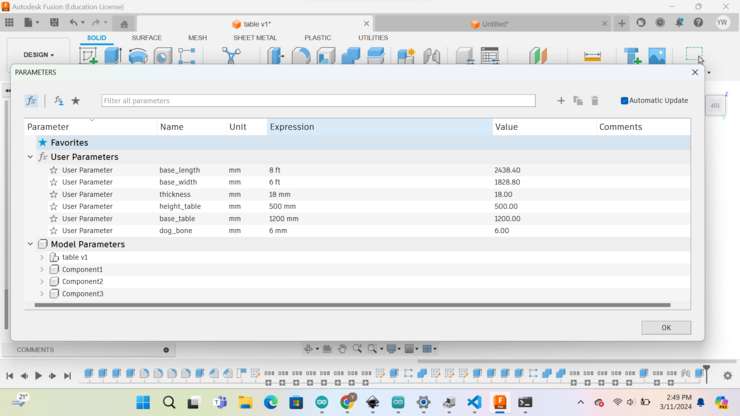
There are a lot of different parameter I set for this design but let get into the main ones.
✓ Height_table - This parameter was set for me to be able to set the height of the table.{500mm}.
✓ Base/Dimeter_table - This parameter was set so that I can have the exact measurement of the top. Since the top of my table is in the form of a circle, it can also be called the dimeterof teh base/top.{1200mm}
✓ Thickness - The thickness parameter is pretty self explanatory as it is simply the thickness of the material I will be using. The purpose of this parameter is something that is really important. While making a 3D model which is a scale copy of the one you are intending to create, it is important to take note of the thickness of the board as without that there is high chances of your joints not being able to fit properly.{18mm}
✓ Dog_bone - Finally this parameter is for the dog bone joints that I would be placing on top of my press fit designs to ensure that after cutting the joints are a perfect fit{6mm}(the done bone has to be the size of the cutting tool used).
Wow, That was quite a lot of parameters I had to set there. Though even with out one of them, this design would have been a nightmare to create💀.
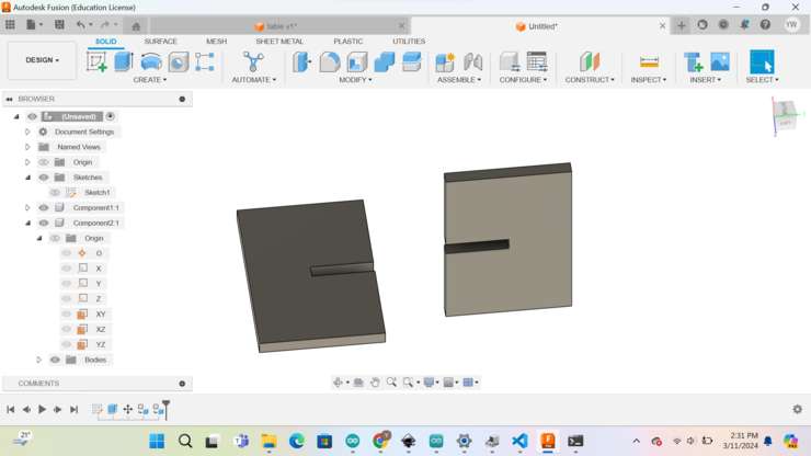
Next up lets get into sketching the legs of the table that I am going to create.
This simple sketch was created by first making a breif outline of the table legs. After that I created some joints on the out line. I created a male joint on the middle of the outline. Additionally I also added the pressfit join to both the legs.😤
Next I extruded one of the legs to really start with 3D designing.
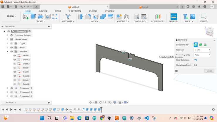
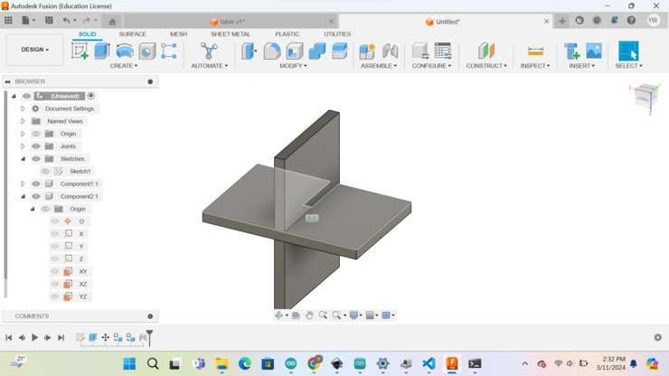
This is how it looks! I used the thickness parameter. With this I have now really started with 3D designing. After that I extruded the other leg and then I joined them to see if that the press fit joint was working😝.

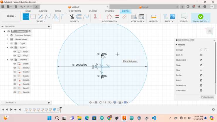
After that I satrted creating the sketch of the top of my table. Additionally I also extruded the top of the table. Thank lord, if I had not created the base_table parameter this entire process might have taken a lot longer🤕.
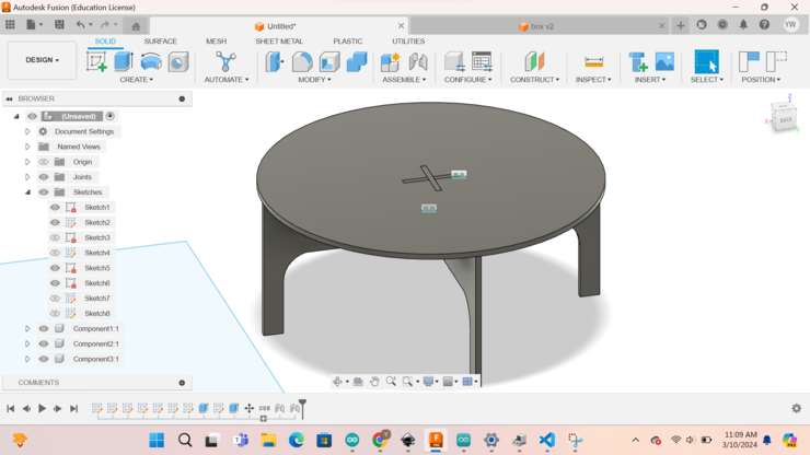
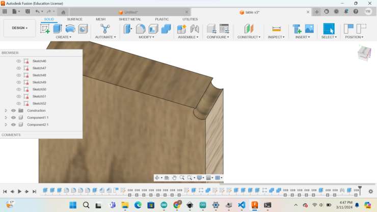
With that I have now completed the absolute simpliest design that I could make. Though that is not going to be enough, I wanted to somewhat 'beautify my design' functionality isn't everything. There also needs to be a bit more astheticsto balance out my design of both functionality and asthetics. To do that I added some filets, added some more joints and also added texture so that it looks like any actual table!!😀
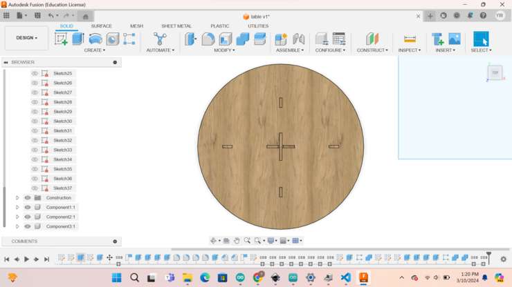
Now that we have seen the alignment of the table, lets now create the dog bone joints onto my design! Though before lets get into what a dog bone joint actually is.
Dog bone joint
Firstly lets talk about waht a dog bone joint actually is. A dog bone joint is a joint that is usually placed on the edges of a design. The reason for this is so that the joints can better fit.
This is the simple tutorial that I used to create the dog bones on my design🥳.
I first had to download the dog bone add-in file from the this link here(dongbone)
after pressing the link you will be led tto this page.
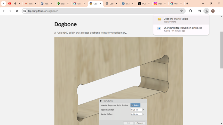
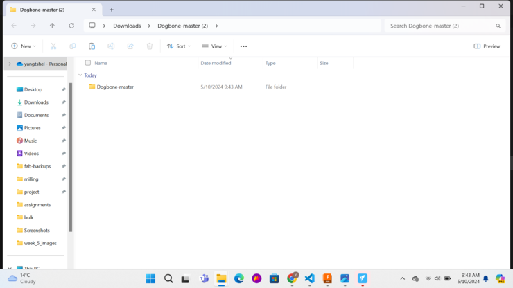
After you are in that page, you will be in the met with a link. Press this link and then the download of the dogbone zip will be downloaded.
Next you will have to unzip the file.
After you are done with unzipping the file, you have to open up fusion 360 and then you have to go to utilities and go to add-ins and then finally go to scriptures and add-ins.
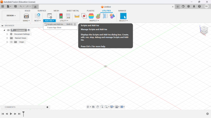
After that we can continue with process by pressing the add-in option form the add_in section.
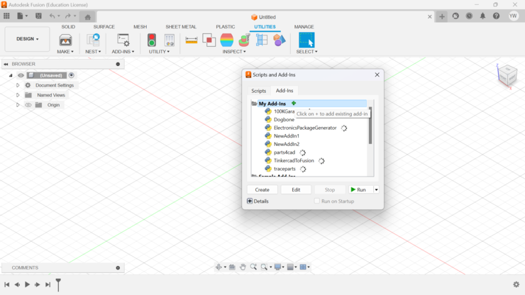
After that just upload the dogbone file to the folder that you are directed to after pressing the add-in option.
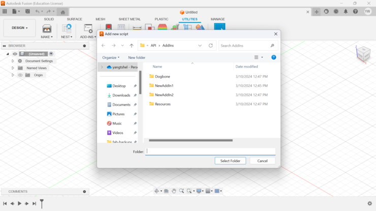
With that I was able to start creating dog bones on my design!
But why do we even need to do so much work for the dog bone? Well, the reason are like so.
Dogbones ensure a proper fit between mating parts in CNC machining.
They compensate for the rounded corners created by the CNC tool, allowing for a tight fit.
Dogbones are circular arcs created outside the edges of the parts, with the point of intersection being the midpoint of the arc.
By using dogbones, the radius of the cutter extends outside of the slot, enabling a good fitment of the parts.
Dogbones eliminate the need for manual finishing of rounded corners and contribute to the efficiency of the CNC machining process.
Adding dog bones!
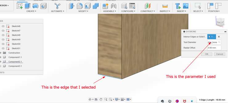
With that I was able to start creating dog bones on my design!
First of all I will be using the dog bone parameter for the dimeter of my dog_bone fillet. The dimeter of the dog bone should be equivalent to the cutting tool that I will be using.🧐
After I had added the dog bone onto all the edges of my design... (That was a lot of work🤐). Though looking back I am thankful that I created those as with them I would have struggled assembling my design🫨.
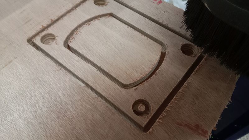
Finally.... my design is complete!😌
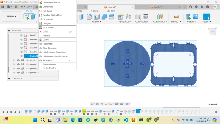
Exporting my design
To cut out my design using the cnc I have to first export my designs in parts.I can do that by simply laying them out in a border that is the size of my cutting dimensions. Then I create the the sketch of the faces of the parts. Then I can simply export the sketch as a dxf file
CNC Milling😾
Now we are going against the main activity of this week.Better change gears as things are gonna get a bit rough😎. Before any of the major action, lets define the dimensions of the plane we will be cutting on.
Cutting plane dimension
✓ Length - 2400mm
✓ Width - 1800mm
✓ depth/thickness - 18mm
In my lab we are using the shop bot CNC PR standard to cut out our designs. Though before we get into how to cut using the CNC, we have to first know how to operate how the CNC😀!
Softwares🤔
Firstly to operate our CNC we need to learn how to use the softwares that control the CNC. There are, in particular two softwares that control the CNC. These two softwares are
Vcarve and the shopbot3.
The workflow of these machine is that first you upload your design to the vcarve software where you can then create your tool path. Then you can simply just use the created tool path and then cut.
Vcarve
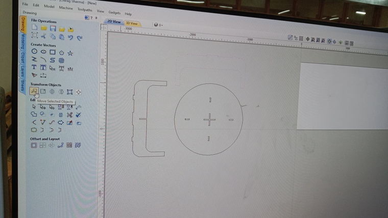
For vcarve you have to first you have to set the dimensions of your material size. For me it is width of 2400mm and height of 1200mm. Also the depth has to be specified(16mm for me). Then with that completed we have to import our design and then we adjust our design on the page that we created. Now you have to press the tool path button and then you will be showed the toolpath settings. This is where you adjust the amount of tabs and other variables. Only after doing all of that can you create your toolpath😬!
Firstly lets create the file that we are going to use to import our dxf file and then start adjusting and our tool path to our desire. To create a file you fist have to select create file and then you should set the dimensions of your plane.
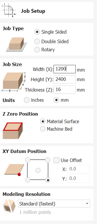
After doing so, you will have a file that is the size of your cutting material. ALso not to forget, always remember to accurately measure your cutting plane as if not it can cause a lot of problems while printing. Also measure the thickness properly, if not, you have really high chances of breaking your mill bit. (if the thickness is less then the real thickness, then the design wont cut. if the thickness is more than the real design, then the design hs chances of coming out before the cut finishes that could potentially cause the mill bit to jam and explode!!!). After setting the dimensions you can simply import your design to the software through the file option.
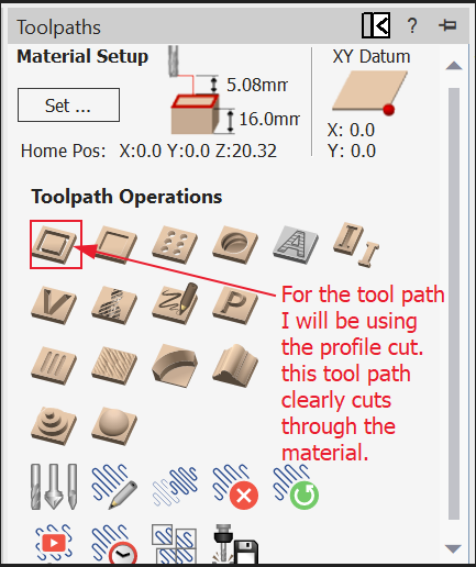
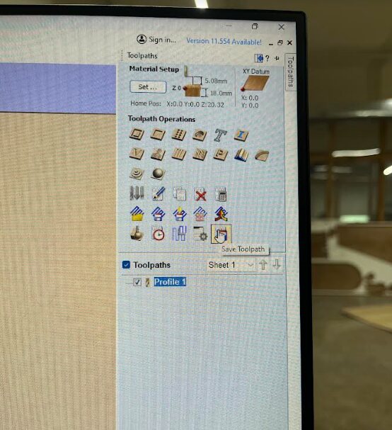
Next we have to press tool path and then select the profile cut tool path. This tool path is to cleanly cut through the material in the shapes your design requires. note*(you have to change the tool paths only after you have set up your design.)

You next have to change the setting of the tool paths a bit.
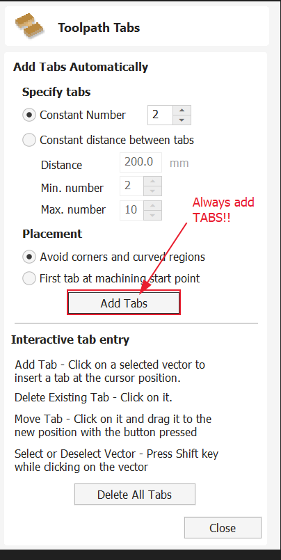
After you have changed the above setting, always remember to double check if you added your tabs or not!
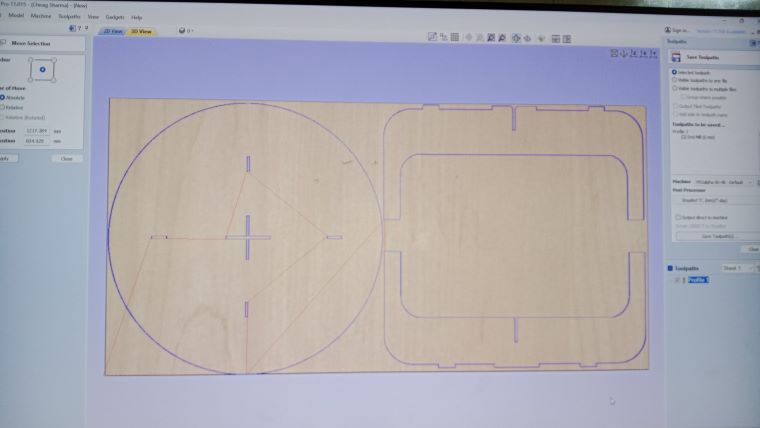
With the tool path all done you just select generate tool path and then press safe tool path option and then see how your tool path has come out.
Lastly we simply have to save our design and then move on to the next precedure which is to adjust our machine using the shopbot3 software.
Shopbot3
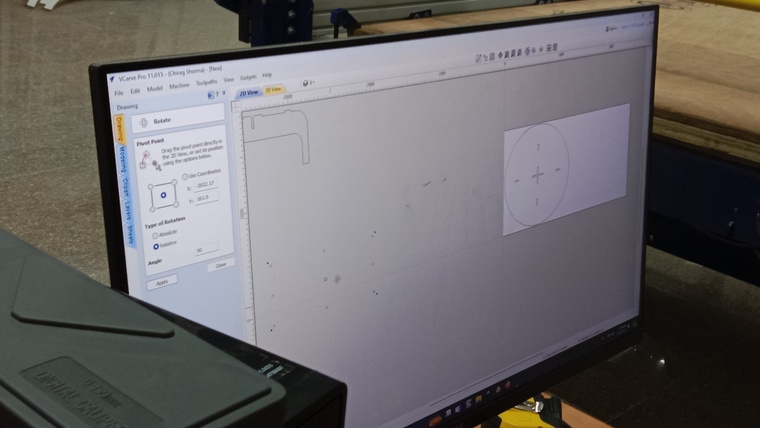
In the previous step we created the toolpath for the CNC. Now lets set up our machine to start with the cutting process. Setting up the CNC mainly includes the setting of its origins. You can either manually set the x and y axis or use the auto origin function to automatically set its origin to the very edge of your workspace. Although the z axis is somthing you cant set automatically. You have to manually do it. You have to place a metal plate on top of the material that you are cutting. Then you lower the endmill to touch metal. Cause of this, it knows that it has gotten the right z coordinates to set as its origin.
Firstly we have to clip in the alligator clip and then make sure that it is securely attached to the machine.
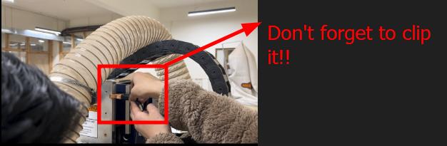
This image has been brought from my friend Damzangs documentation with her permission
Then press the z-axis zeroing button on the shoopbot3 which will make the mill bit slowly lower down.
Ensure that you have the metal plate placed right down on you material bed.
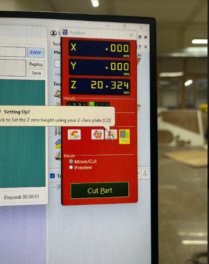
This image has been brought from my friend Damzangs documentation with her permission
After the zeroing is done, remember to put the clip back to its original place.
Now that I am finish with setting up the machine, now I can simple just print my design.
Cutting Process
Firstly I simply have to press the start option to begin with with my cutting process.
After pressing the cut button, you will be faced with a page asking to turn the on the spindle of the machine and then also to ensure that the vacuum is turned on and ready to start with the printing process.
To start the spindle by the using the button right here!
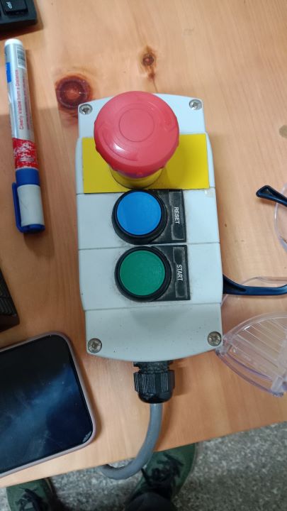
RED button - the red button is the emergency stop button(press this if any mishaps happen between printing).
GREEN button - the green button is the start button to start the spindle(press this to start the spindle and start with the printing).
BLUE button - this is the reset the button. This will reset the machine(Do this right after you turn on the machine.)
After that we simply have to start the vacuum by pressing this button down.
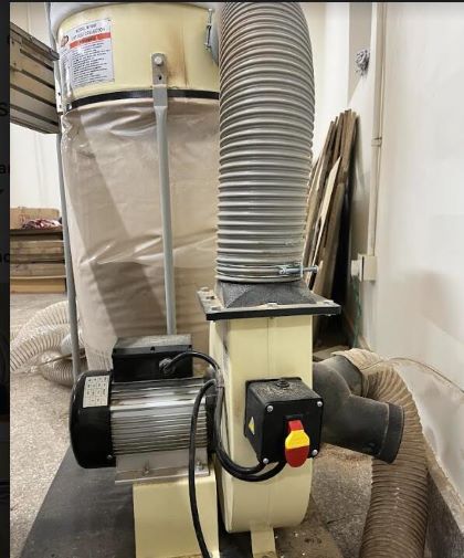
This image has been brought from my friend Damzangs documentation with her permission
Now finally we can start with the printing process.
assembly
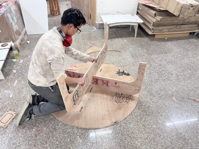
The assembling the table was simple enough as my design only had 3 parts. I first put the two legs together and then after I placed them on top of each other, I just lied the table top on the ground and then placed the joined legs to the table top.
Hero shots!!!
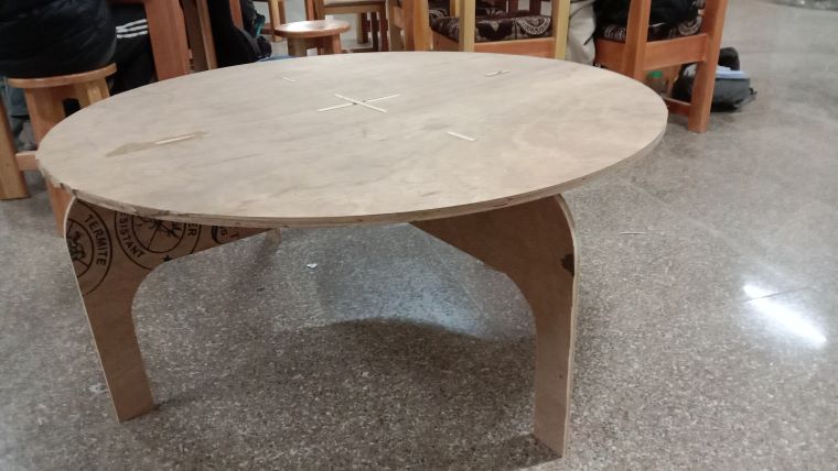