Group assignment:
Browse through the datasheet for your microcontroller Compare the performance and development workflows for other architectures Document your work to the group work page and reflect on your individual page what you learned
Individual assignments
Write a program for a microcontroller development board to interact (with local input &/or output devices) and communicate (with remote wired or wireless devices)
Implement programming protocols.
Linked to the group assignment page Programmed your board to interact and communicate Described the programming process(es) you used Included your source code Included ‘hero shot(s)’
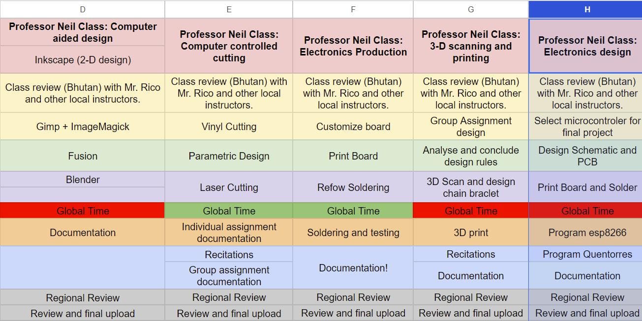
Here is the complete group assignment
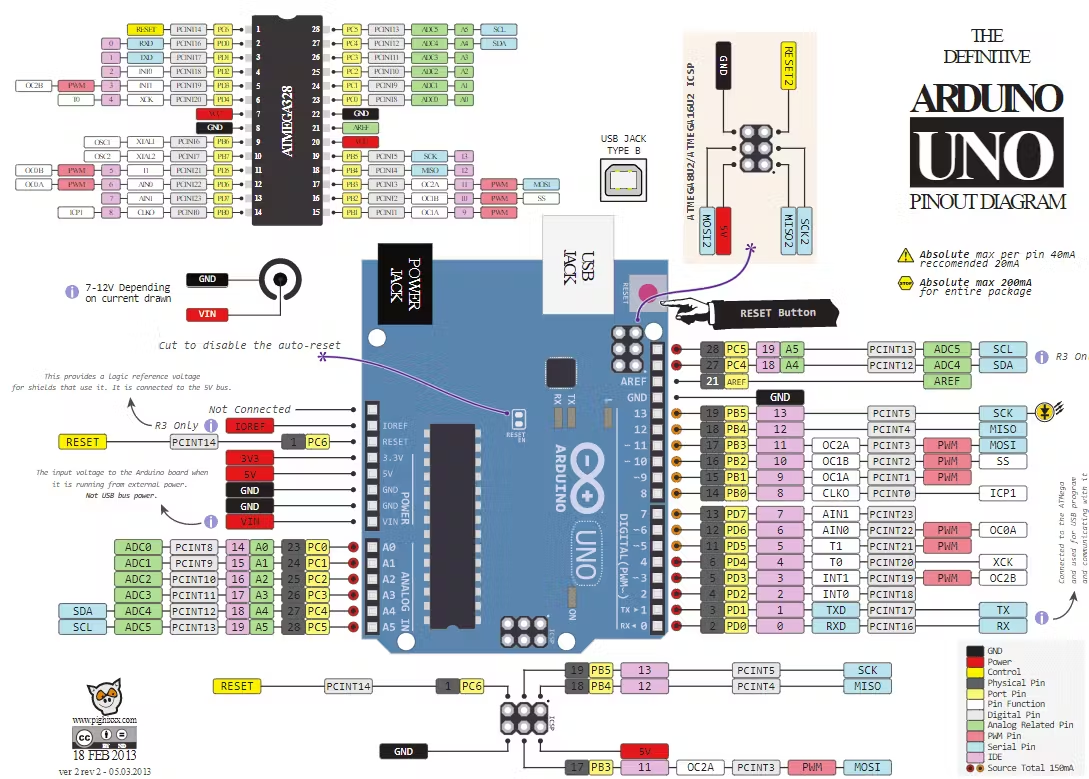
Arduino UNO is a microcontroller which is powered by Atmega328P processor and thereby it serves as the main processor. This is the Atmega328p which is equipped with 14 digital input/output pins ( among which 6 can be used as PWM outputs), 6 analog inputs, 16 MHz ceramic resonator, USB, power jack, ICSP, and a reset button. The circuit board is a self-contained entity that provides all the power bus, as well as other resources to the microcontroller.
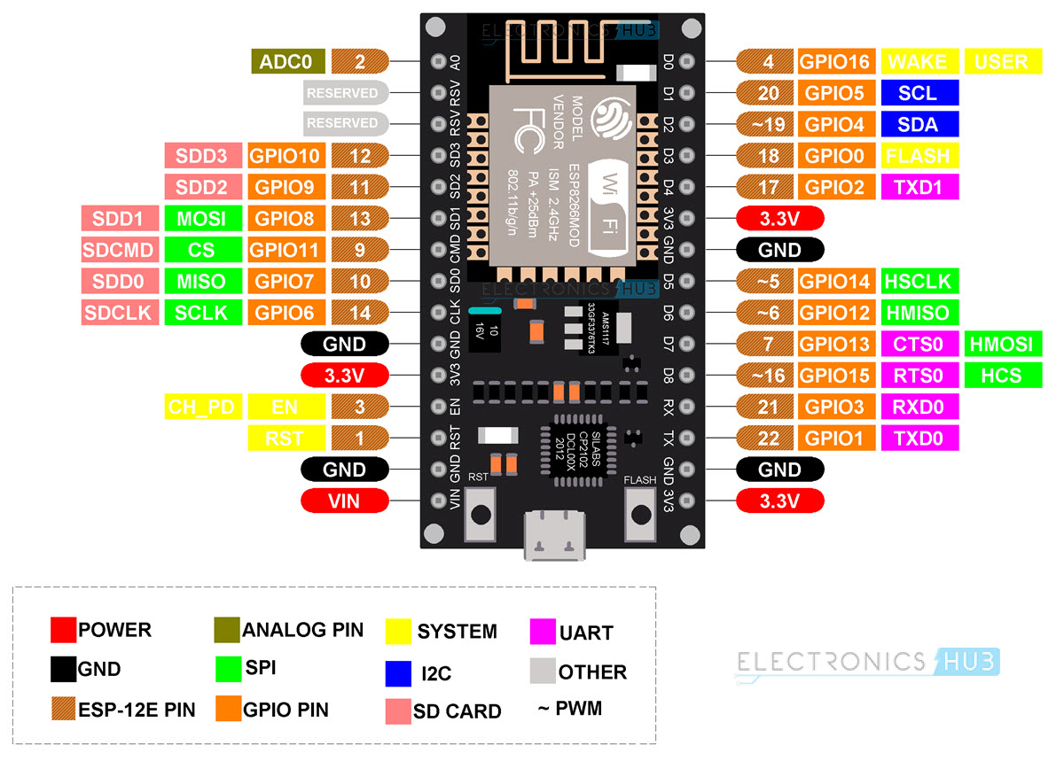
ESP8266 board ESP8266EX is capable of functioning consistently in industrial environments, due to its wide operating temperature range. With highly-integrated on-chip features and minimal external discrete component count, the chip offers reliability, compactness and robustness.
ATtiny 45 The attiny45 microcontroller is from the AVR family, which provide a compact size microcontrollor to interface and controll outputs and input devices based on the pin confriguration.
KiCAD is a free software for developing schematics and PCBs designs. It not only provides the users with the schematic drawings for electric components but also directly helps them provide the physical layout for the PCB configuration which will show the correct placement of components and trace routing.
Step 1: Install KiCad
I downloaded and installed the latest KiCad version from the official KiCad website.
Step 2: Open KiCad
Then I launched KiCad after a successful installation.
Step 3: Create a New Project
Select "File" -> "New Project" -> "New Project."
Set the project name and location.
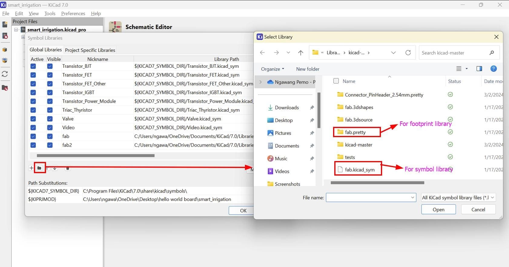
To add libraries in KiCad, first download your desired library. For my board I downloaded the library from here.
Then in the project window tap on preferences and choose either symbol library for components and footprint library for components' footprint.
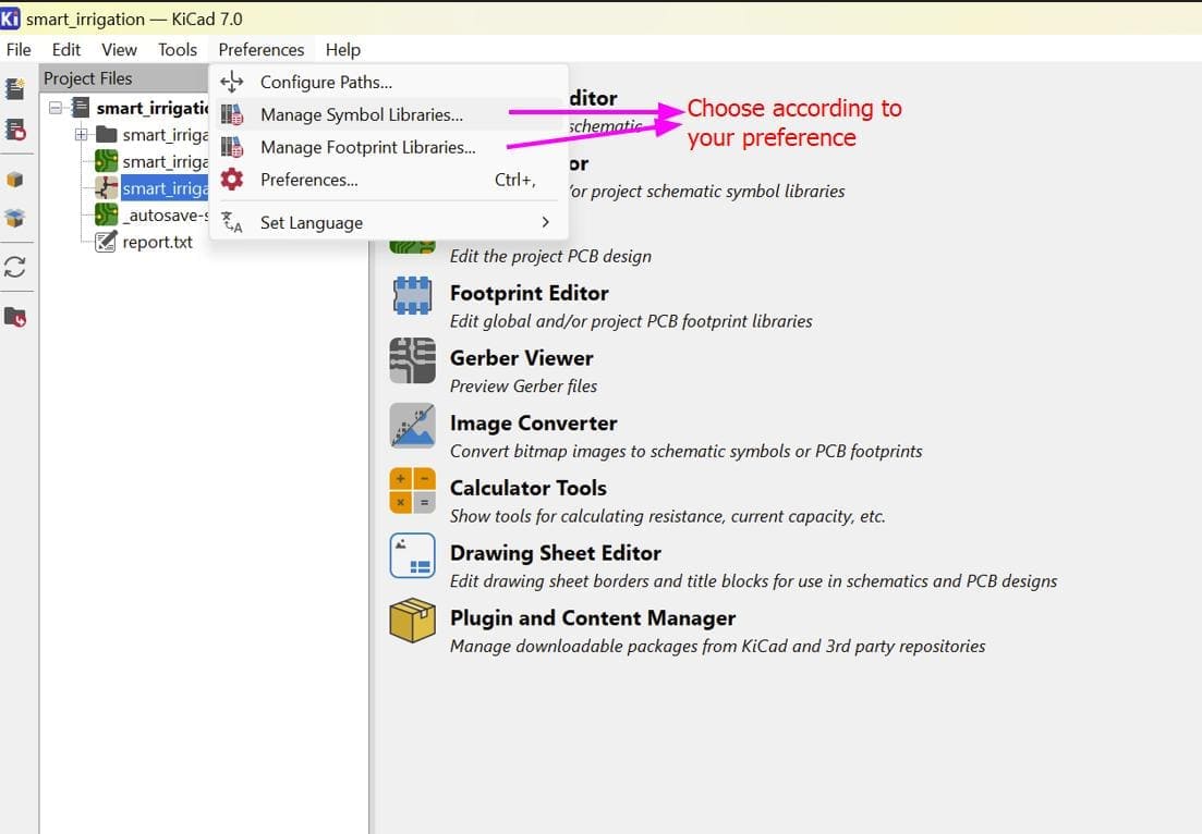
After that a square will pop up where you can select the folder icon and add the downloaded library.
In the project window:
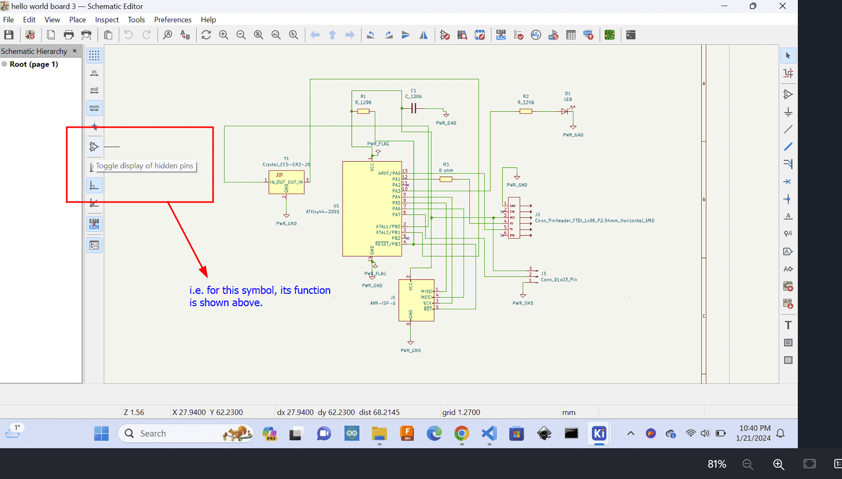
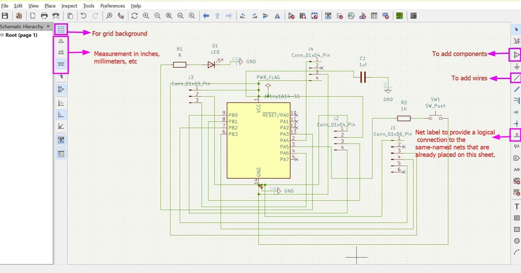
Here are some basic tools you have to use for a schematic circuit:
So, for this week, I am planning to work on my final project board and I chose ATtiny1614 as my micro-controller. Here is the pinout of the mcu.
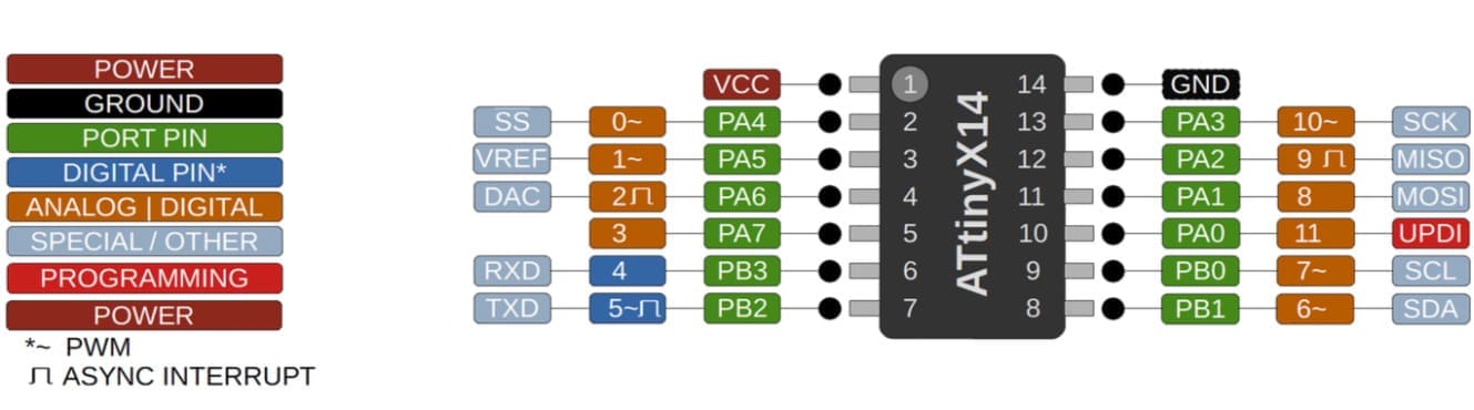
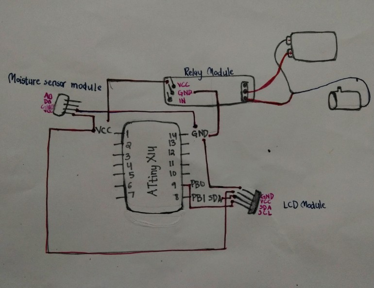
Last week, I sketched a simple circuit diagram for my board with ATtiny1614. Before sketching the diagram, I wrote down all the pin connections when programmed with an arduino uno.
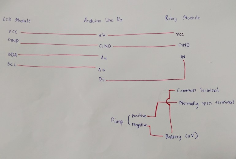
And here is the circuit diagram that I drew:
In the file I double-clicked on the schematic file in the project window to open the Schematic Editor. Then I used the left toolbar to place components onto the schematic. Then I clicked on the "Place Symbol" icon and added components like resistors, capacitors, and integrated circuits. After adding all the components, I used the "Place Wire" tool to connect the components and clicked on the pins of the components to create connections.
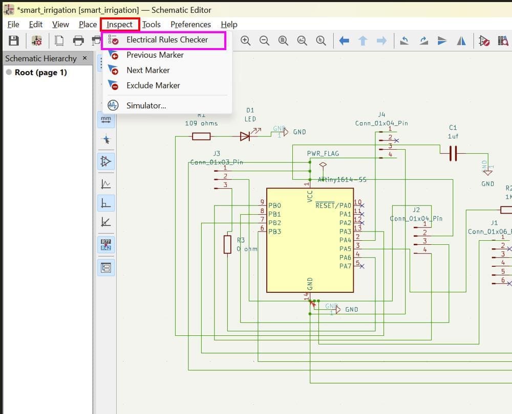
Run ERC
While designing your schematic board, don't forget to run the electrical rules checker to find errors or incomplete connections in your design.
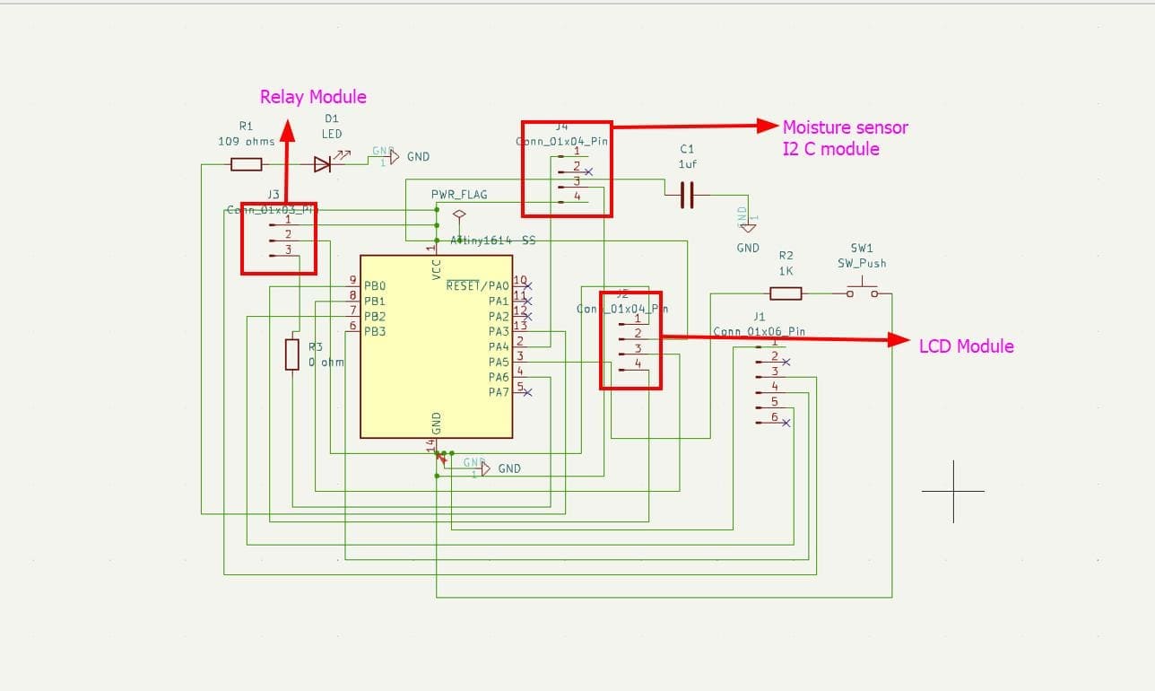
Here is the final look of my schematic circuit:
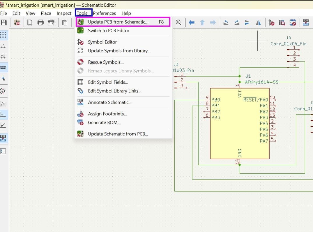
Now to update the schematic to PCB format, first click on tools and then select update PBC from schematic option.
To create the PCB design, I first arranged the components in a convenient manner. Then I used the routing tool to create traces between component pins, ensuring proper connectivity. For this, I continuously adjusted component placement until an optimal PCB layout is achieved, considering factors like signal integrity, power distribution, and manufacturability.
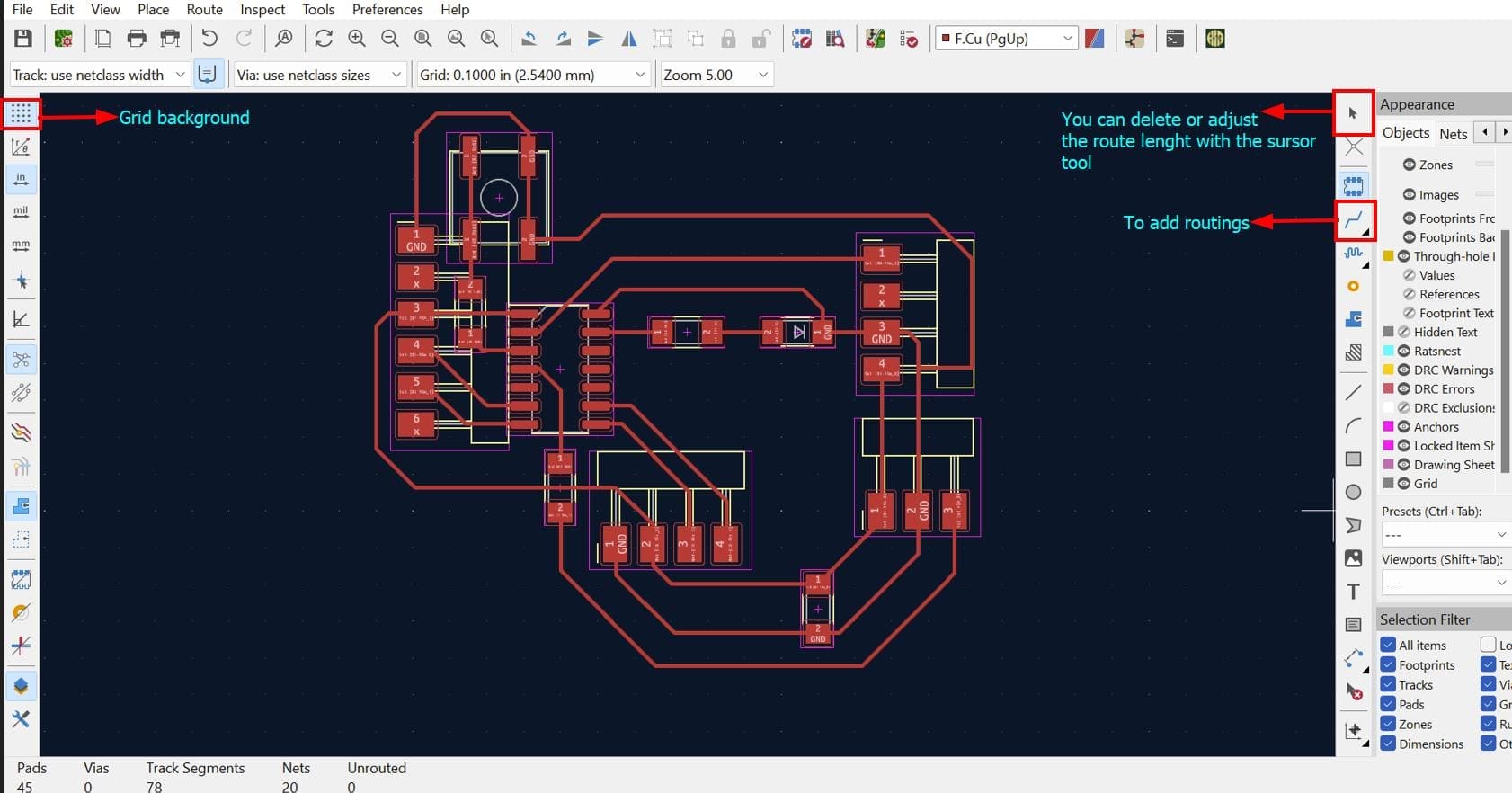
Thanks Thinley for the help
While creating routes, we should also keep in mind to avoid right angle connections because according to Altium, "high-frequency signals emit Radio Frequency radiation at every 90 degree turn of the copper track." (Altium, 2018, para.3)
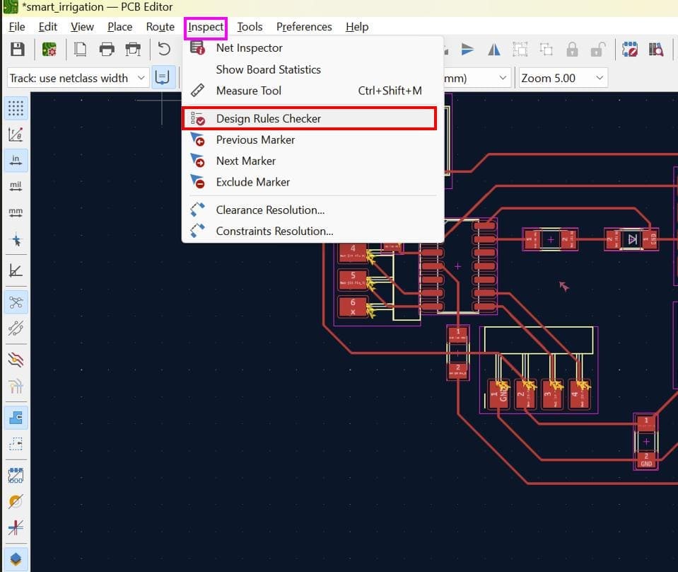
Run DRC
Like you ran ERC for schematic, it is also important for us to run the design rules checker for PCB design to ensure there is no design error in your board and guide you to improvise your board.
To program the ATtiny1614 I followed this tutorial and I also referred to Adrian's Documentation
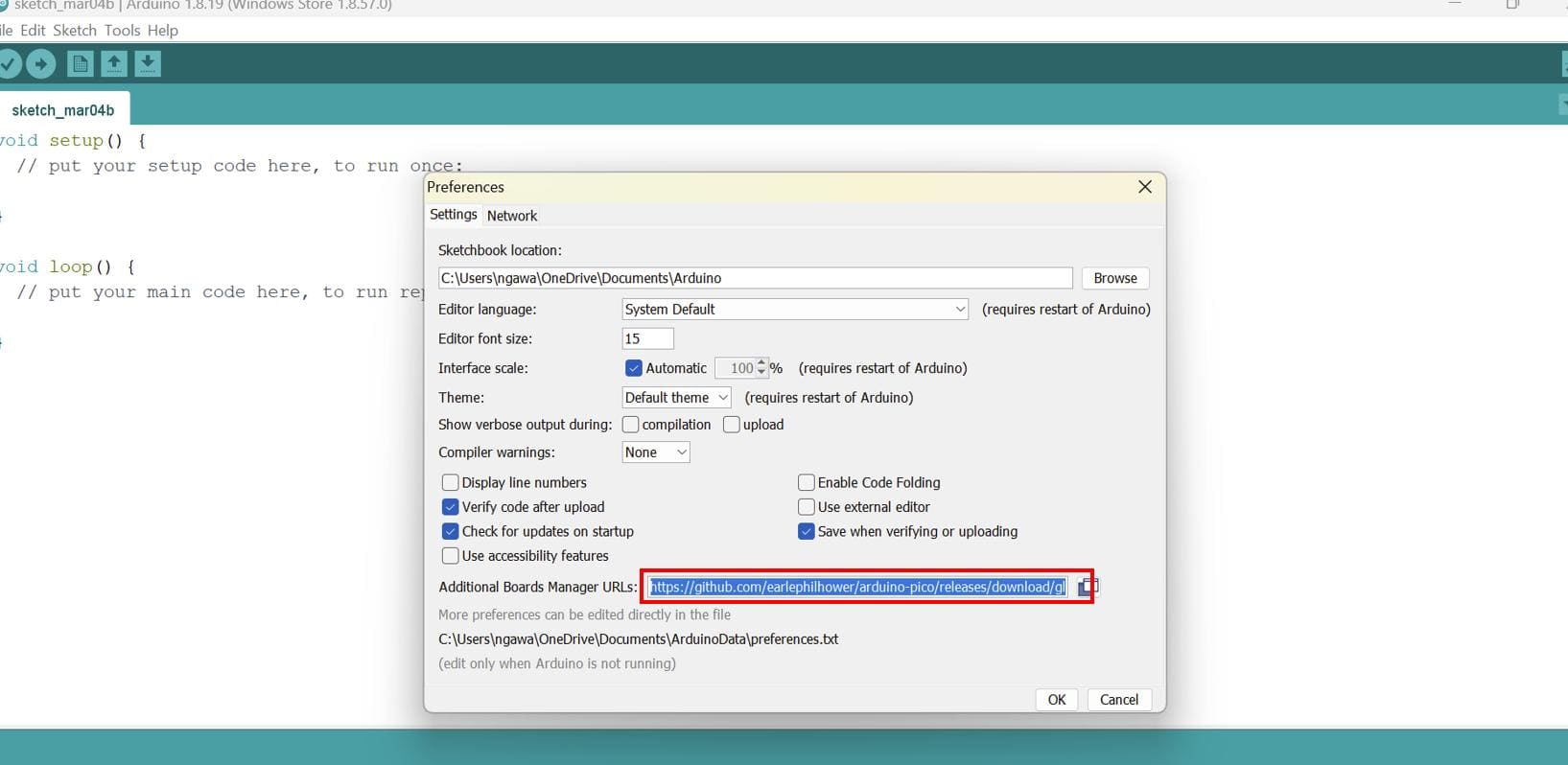
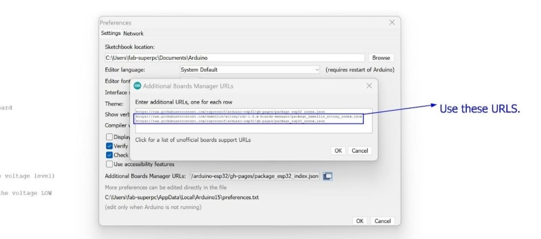
Now, open your Arduino IDE and go to files > preferences. Then paste the link in the Additional Boards Manager Urls
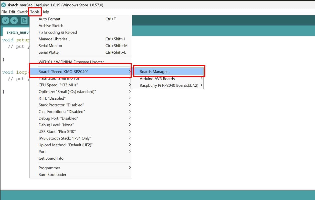
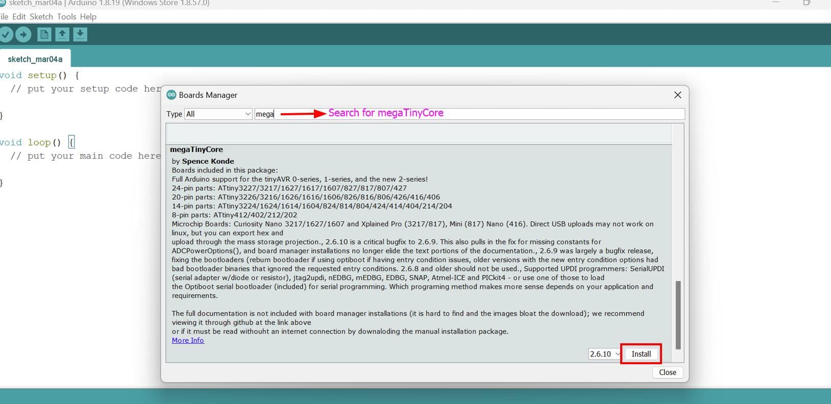
Now, go to tools > board > boards manager
Search for megaTinyCore and install the file
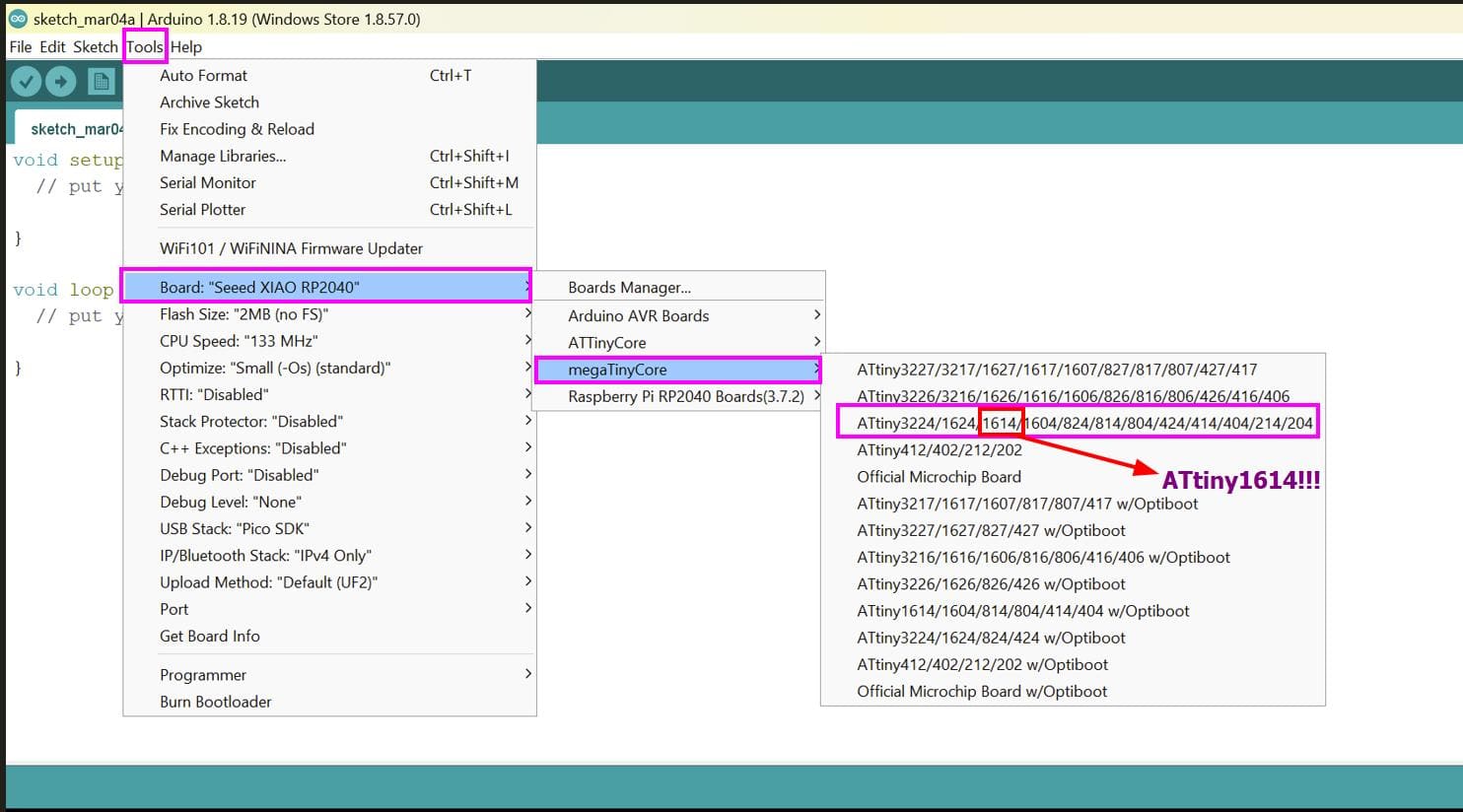
After the installation, go to tools > board > megaTinyCore > select the section which has the ATtiny1614
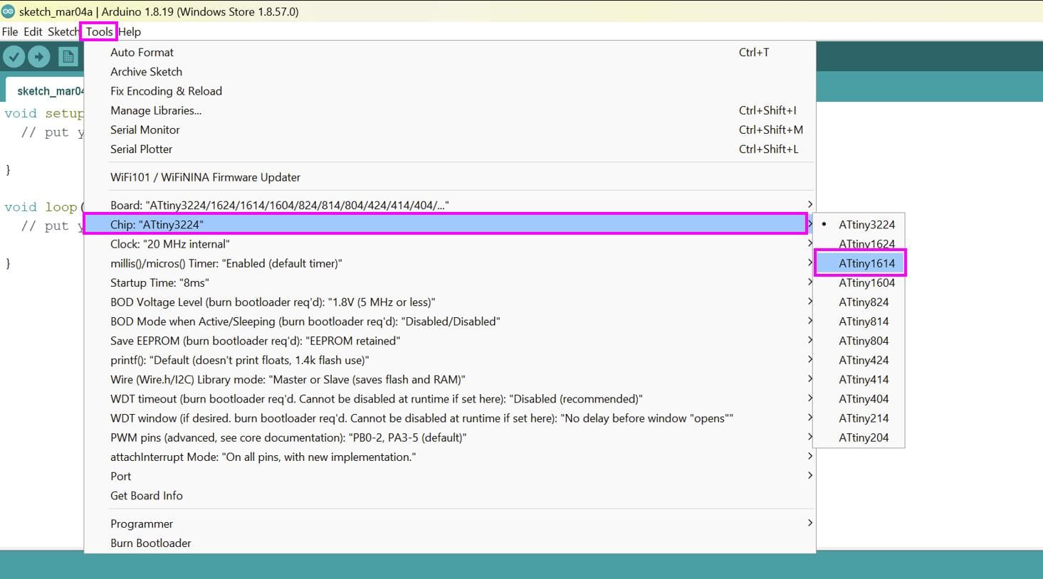
Now, hover your cursor to chip and specify it as ATtiny 1614
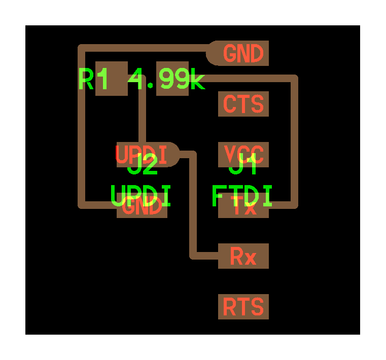
Then I decided to design a UART to UPDI connector with an embedded 4.7 k resistor between TX and RX by referring to this link
I was about to print but the milling machine was having some problems, so Sir Anith suggested us to use the breadboard
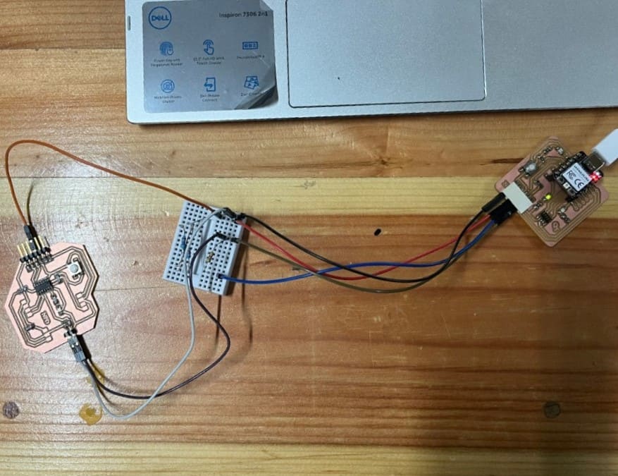
So, here I connected the same pins with a common row. I also followed the color code for VCC and GND. Here, you can see the connections.
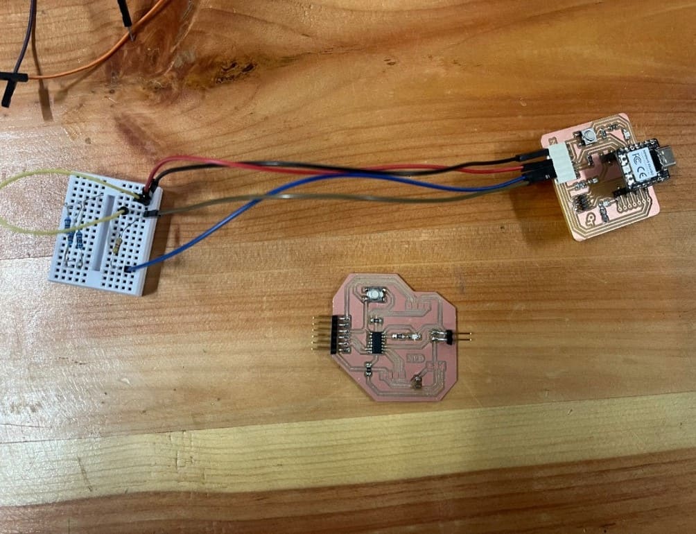
After I made all the connections, I connected my board to the breadboard and the Quentorres to my laptop.
Note: Always put a power LED to your board to ensure there is no issues with the power supply
I forgot to put a power LED, so I can not tell if my board works or not :(
Now, refer to the Quentorres board tutorial to proceed with the remaining steps.
My pymcuprog failed to communicate with the ATtiny so I followed the guide given separately named solution.
1. Install python3 and pip
I already had python installed, so I proceeded with the next step.
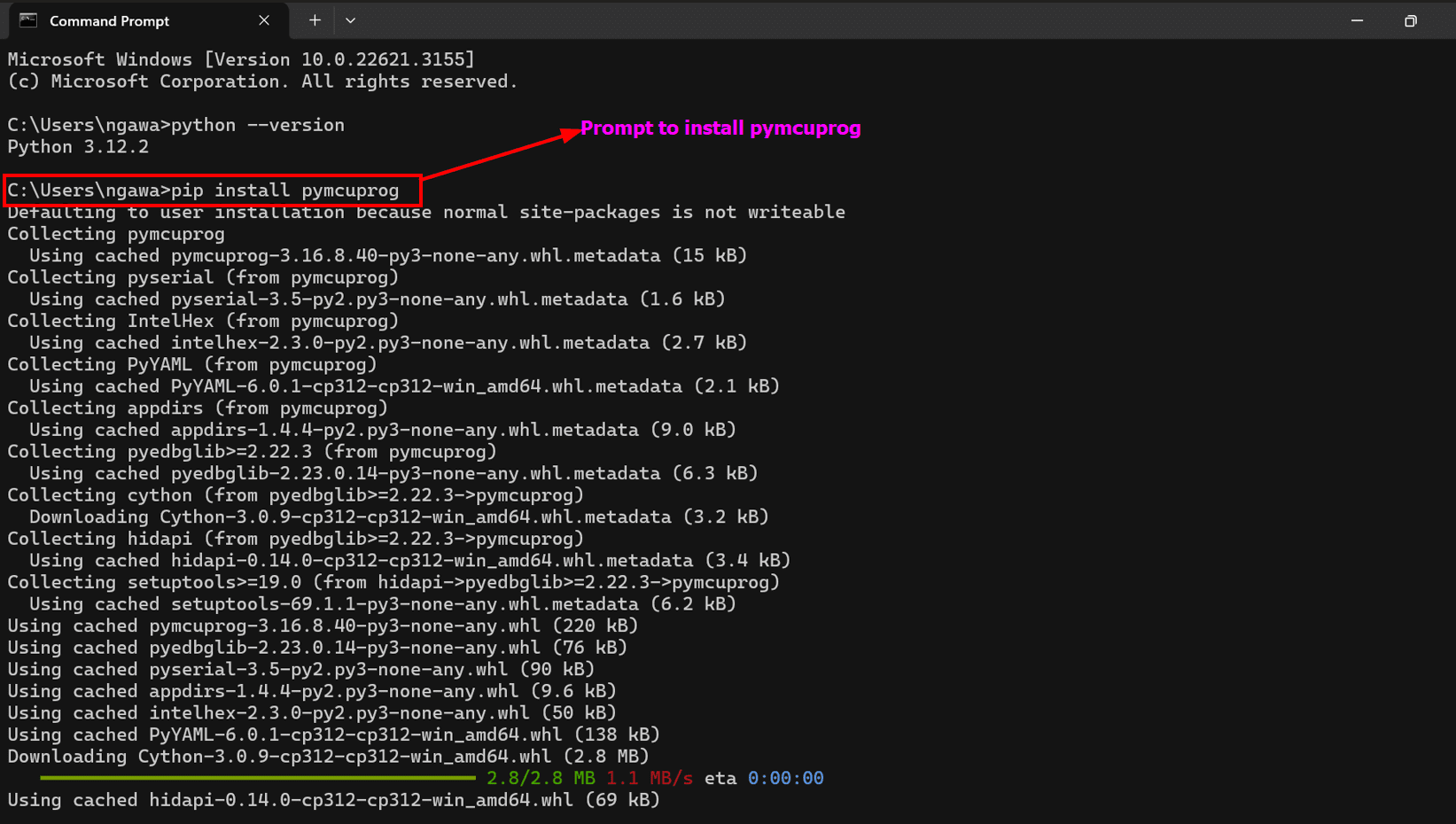
2. Install pymcuprog
I used this prompt pip install pymcuprog in cmd to install pymcuprog.
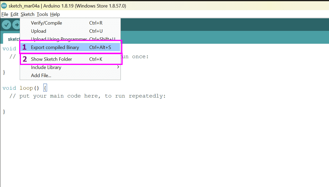
3. Determine .hex File Location
Go to Sketch > Export compiled Binary.
Go to Sketch > Show Sketch Folder to find your .hex file.
Then I navigated to the folder using windows powershell.
4. Program the Board
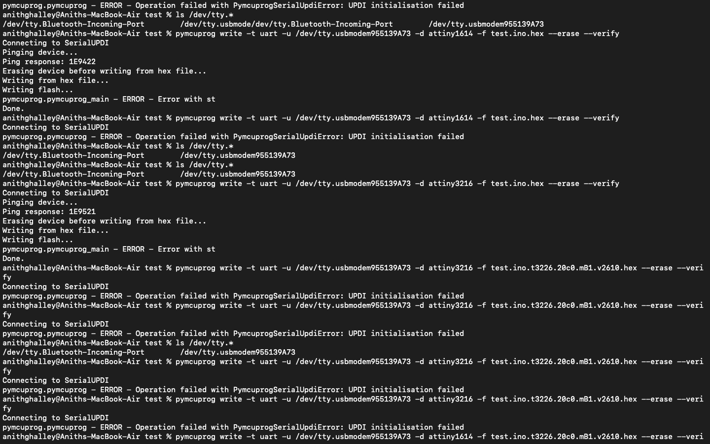
Depending on my chip, you can replace -d attiny1614 with your device (such as -d attiny412). Also make sure that /dev/ttyACM0 is the serial port of your programmer. You can see the name of it in Arduino IDE under Tools > Port.
pymcuprog write -t uart -u /dev/ttyACM0 -d attiny1614 -f BlinkATtiny.ino.hex --erase --verify
After running this code, there were some issues uploading.
We ran the code several times but it still showed error.
As I am running out of time, I will do the updi programming in the coming weeks and for this week I will try to program the Quentorres and ESP8266
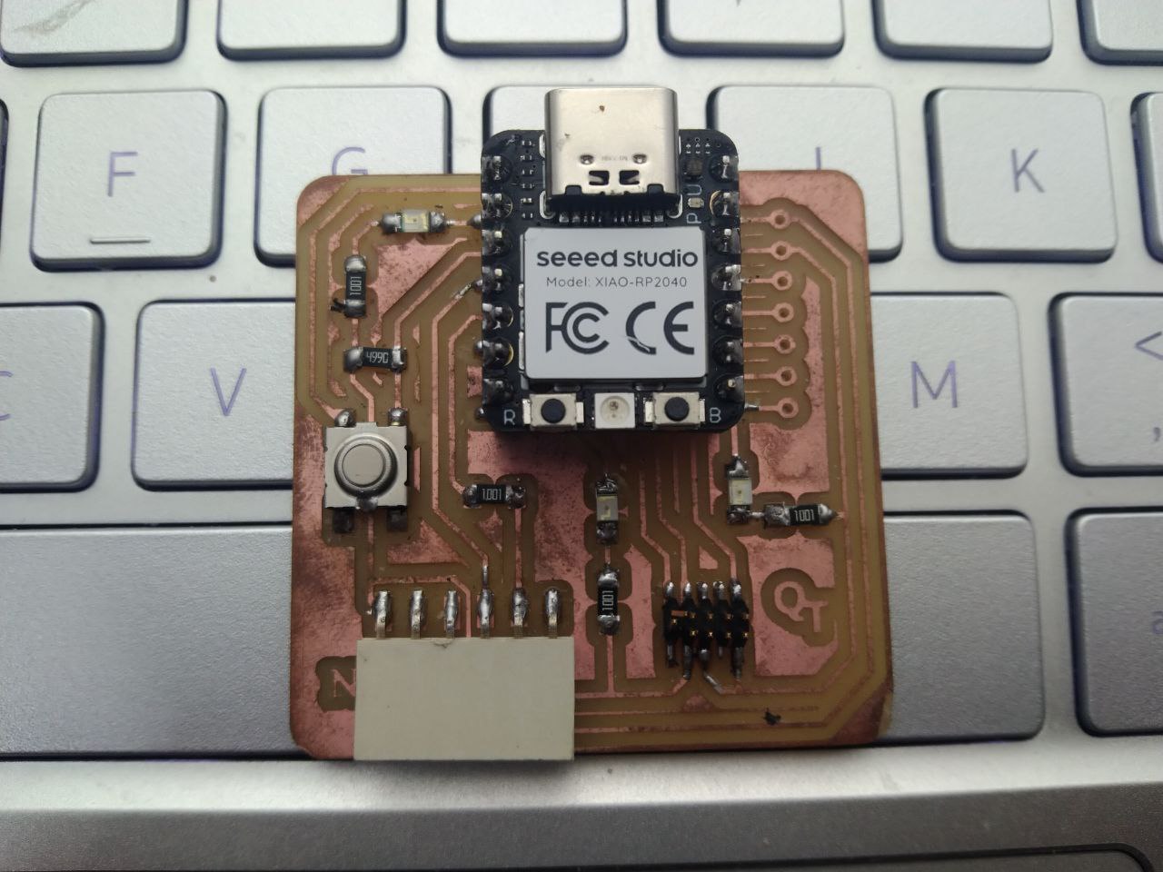
To program the quentorres board, we first need to add the URL of addtional boards. _You can find a more detailed guide in my week 4 documentation_
Then go to tools > boards > boards manager > download pico board from here
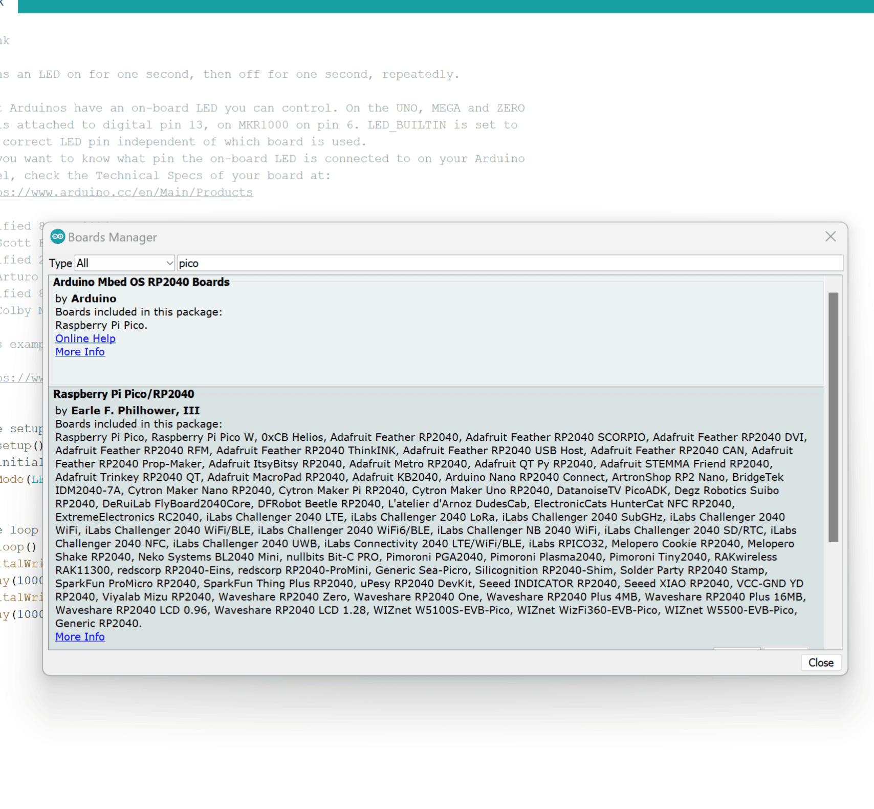
Then I configured the Arduino IDE for the Seeed Studio XIAO RP2040. Look for the device in the COM port, such as COM 3.
Then, go to boards manager and select the board from there.
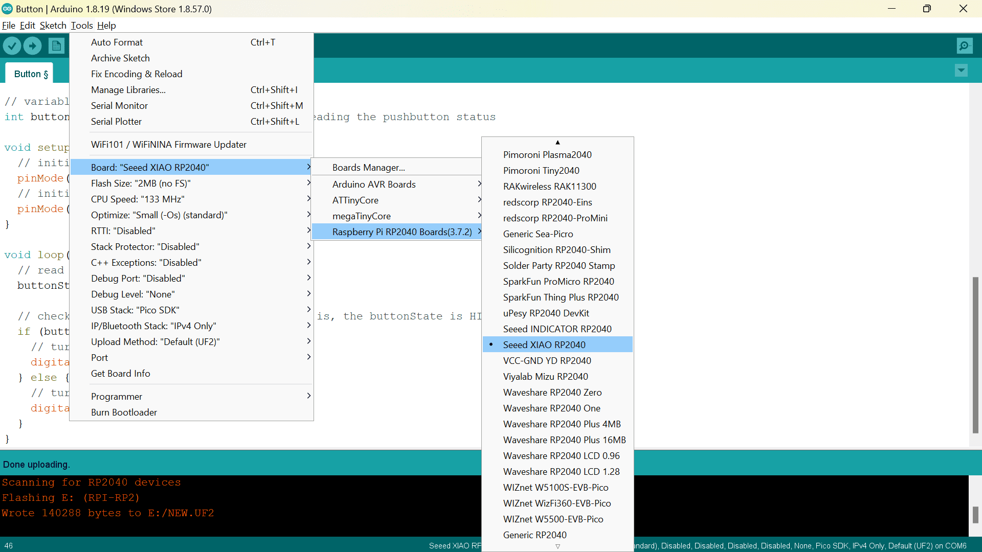
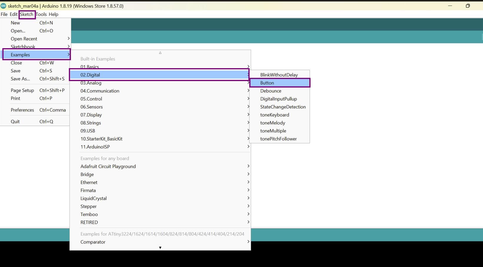
Now, upload the inbuilt button program.
And here are the results!!
Last time, I tried to program the NodeMCU esp8266. Before starting, here is a short description of the esp. The ESP8266 is a low-cost Wi-Fi microchip, with single chip CPU with GPIO, Analog channel, Serial channels, I2C, SPI, and most importantly on chip Wi-Fi.
First, I connected the NodeMCU esp8266 to my laptop with a USB C to USB A cable.
To ensure that the mcu is connected you can go the the device manager
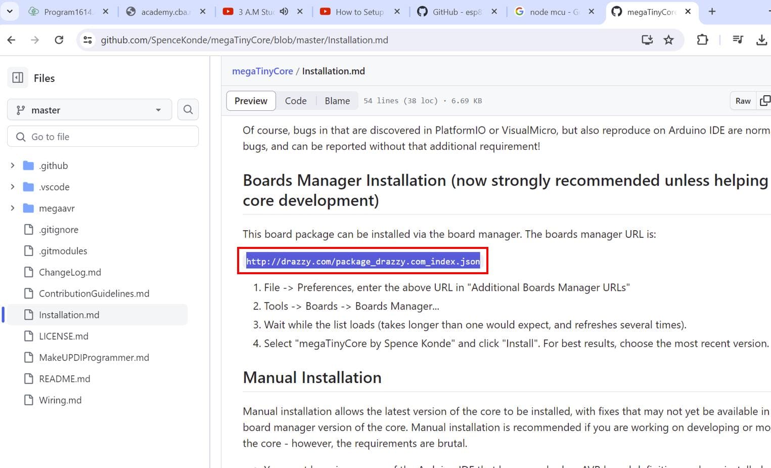
After that, download specific packages for NodeMCU esp8266.
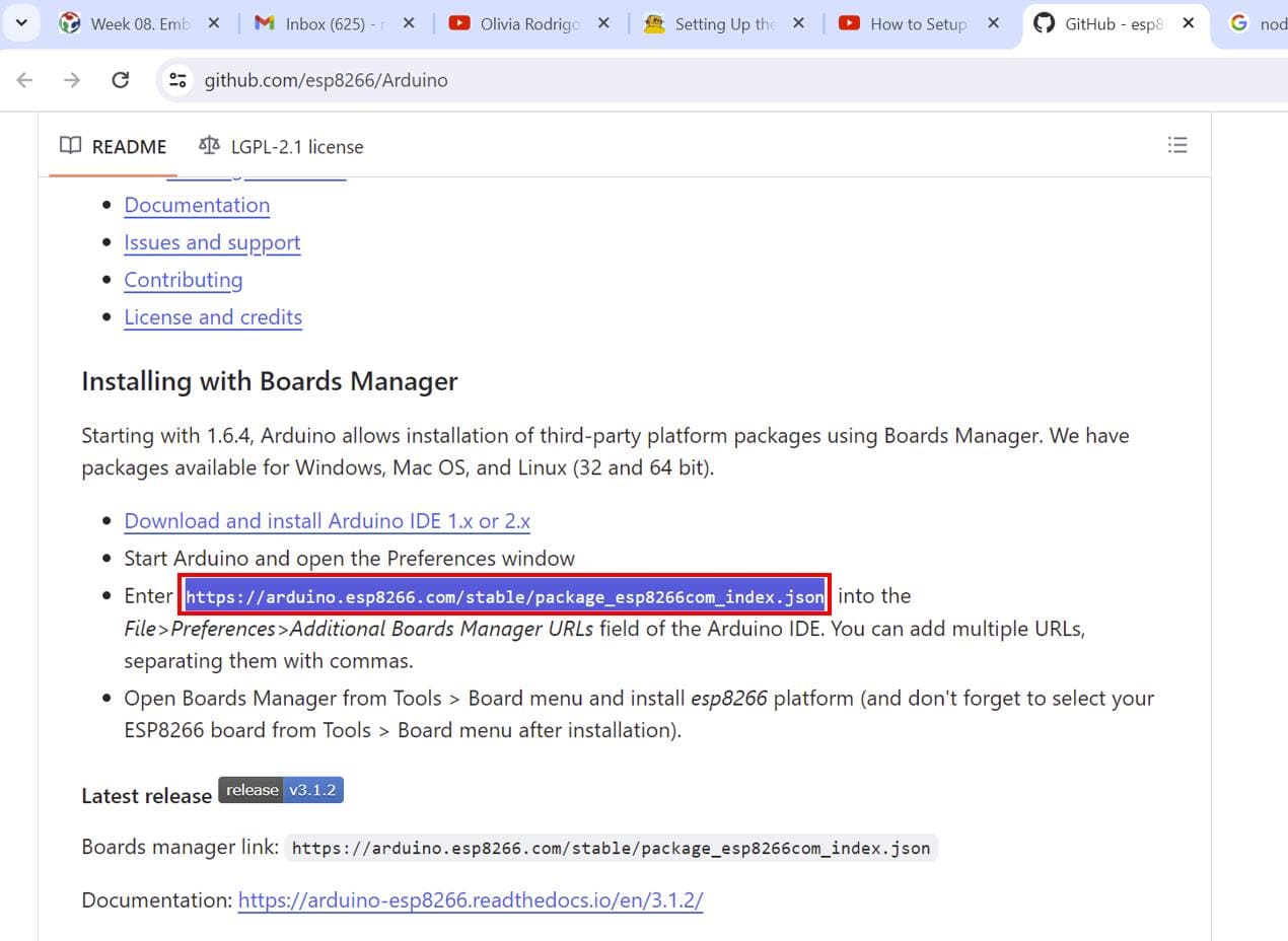
To download the package, click on this link.
Scroll down to the Installing with Boards Manager section and copy the link highlighted below.
Now, open your Arduino IDE and go to files > preferences. Then paste the link in the Additional Boards Manager Urls
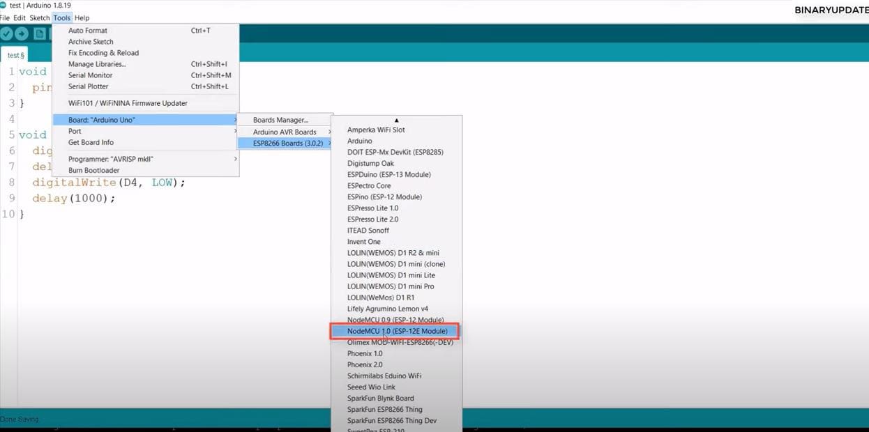
Then go to boards manager and install the esp8266
Select the board and upload the blink program after inserting the correct pin no.
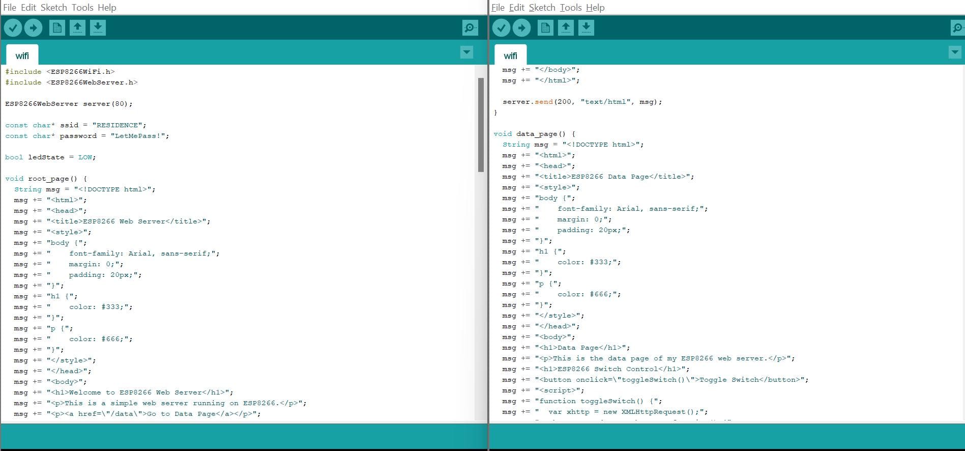
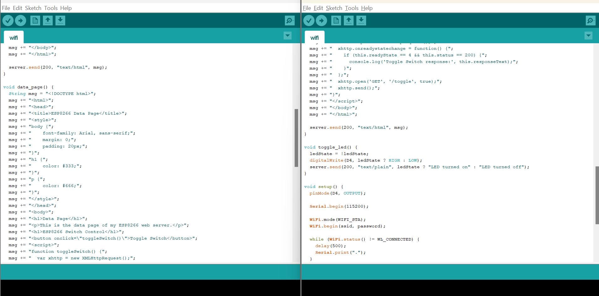
Now I am connecting the board to WiFi and creating a web server that I can control the LED with the IP address on any device.
Here is the code that I got from this YouTube video
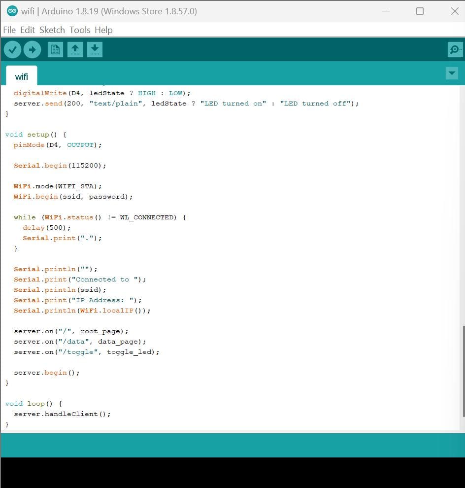
Now go to serial monitor and hard reset. The board is now connected to WiFi.
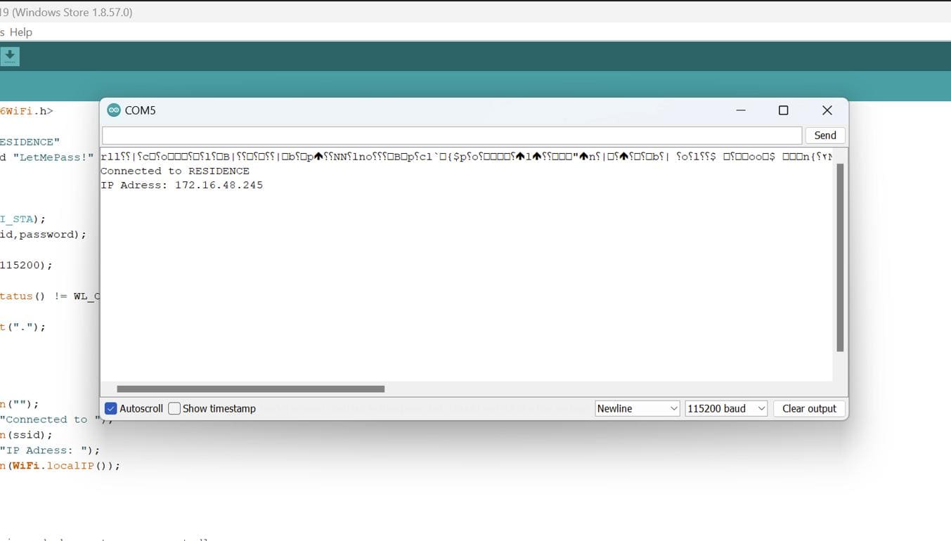
If you copy the IP address and browse it on any browser, you should be able to control the LED.

I forgot to take a picture of my interface do I got a similar one from google!
After the upload process!!.
Code Files: