Implement programming protocols.
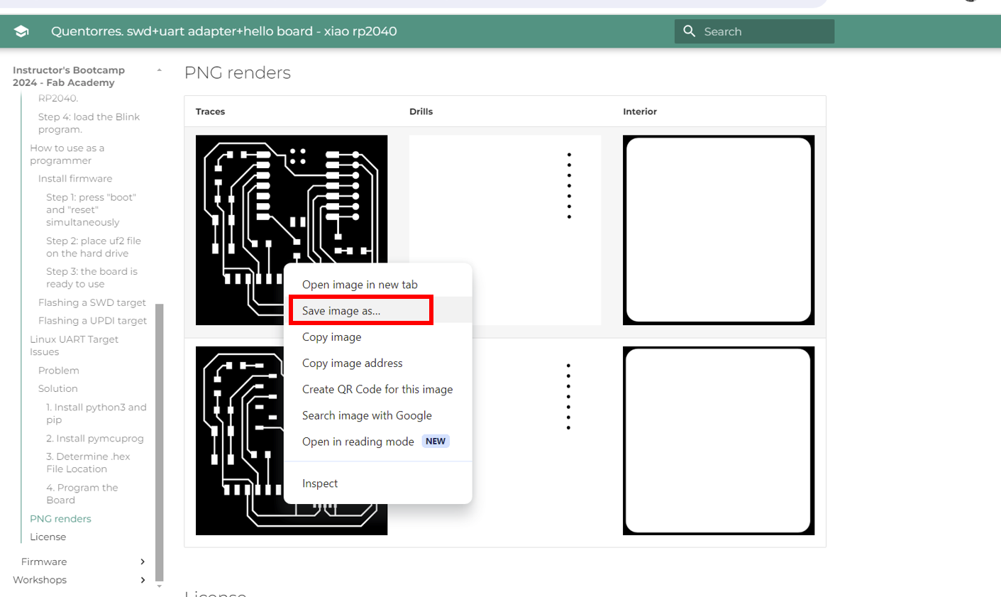
For our group assignment, we started by getting the PNG images from the fabacademy website.
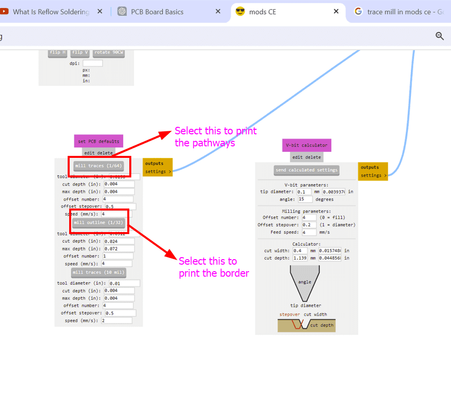
We used a 1/64 inch bit to make the traces. Here's what we found:
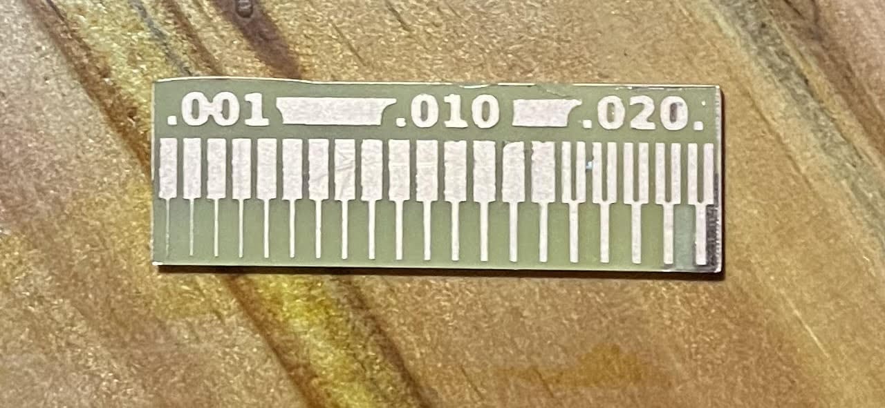
After looking very closely, we discovered that the size as well as spacing of the traces are just clear within the 0.020 array. This is due to the fact that the 1/64"" little bit is 0.015, as well as 0.020 is the only dimension that's larger than that. So for our future circuit boards we require to stick to this array.
Here's our group assignment link!!!
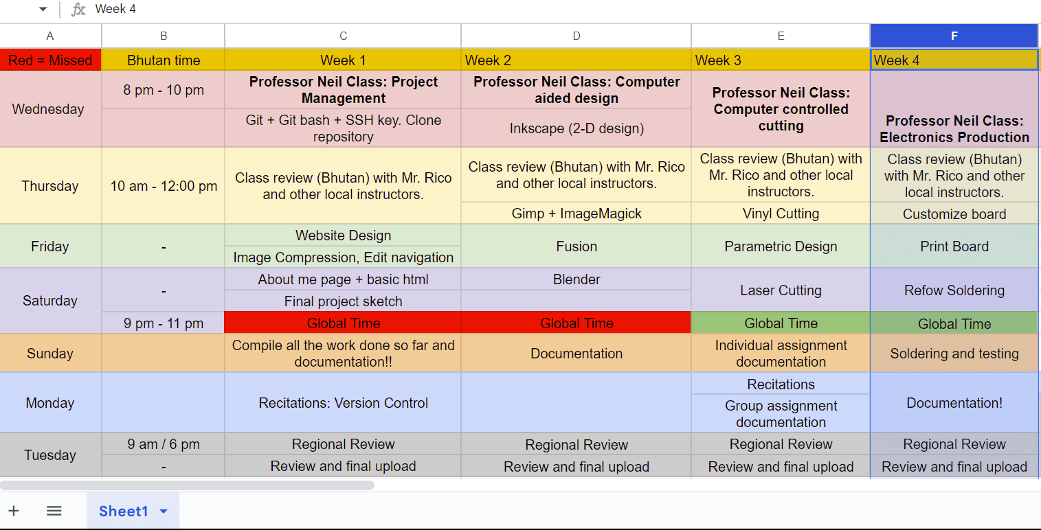
Week 4 - Electronics Production
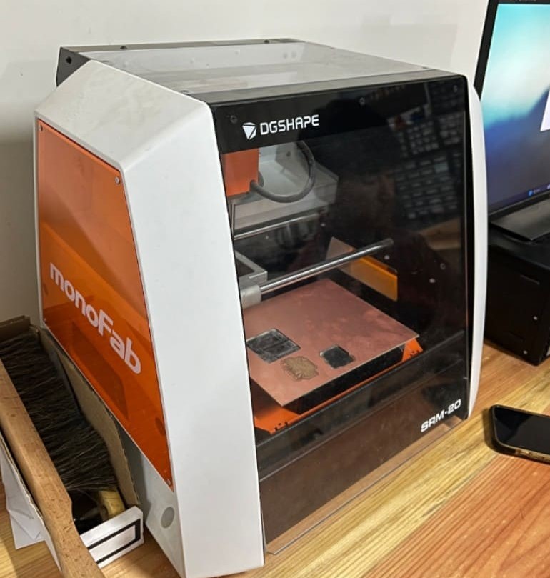
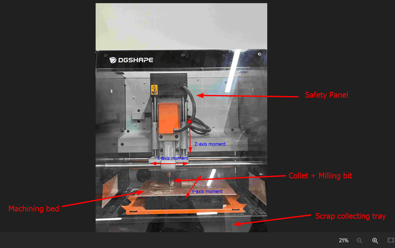
As a small milling machine, the SRM-20 offers compact size and powerful functionality. Production of realistic parts and prototypes is made simple and convenient with a device that fits into any office, home, or classroom environment. For users looking for advanced milling capabilities without the need for expert operating skills, the SRM-20 is the easiest and most precise CNC mill in its class.
The Quentorres board, created for the Xiao RP2040 microcontroller, works as an adaptable SWD+UART adapter plus hello there board. It assists in programs in numerous languages like C, Rust, Go, and also Micropython, including elements such as responsive buttons, LED signs along with outbreak pins. The board supplies adaptability, enabling straight link or usage with ports. Guidelines cover use as a hello there board as well as developer consisting of blinking targets like SWD as well as UPDI. Fixing pointers for Linux UART target concerns are likewise supplied together with software application installment advice.
To mill the board, I first referred to the intructor bootcamp guide in the fabacademy site which has detailed information of the Quentorres board. I came to know that the original programmer was created by Quentin Bolsee` and later redesigned by Adrian Torres.
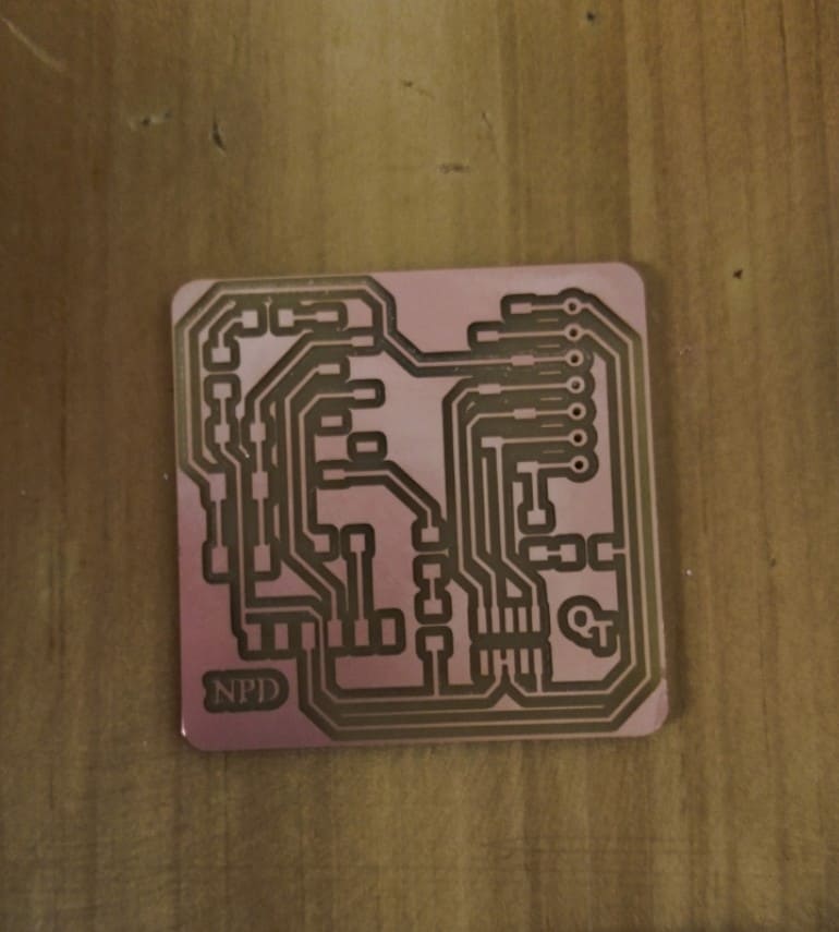
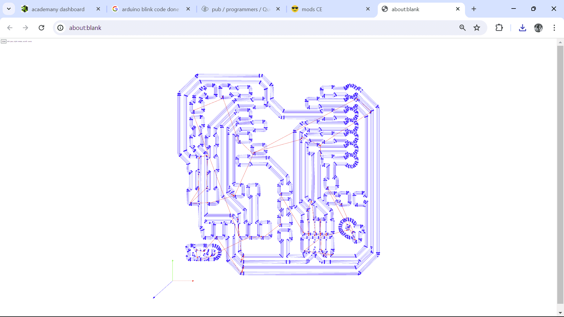
There was PCB format of the board which I downloaded as image.
During my first try, I inverted the already inverted image and ended up having the routes cut the opposite way. So, I had to do over!!
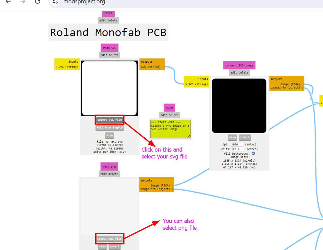
To check the DPI (dots per inch) of an SVG image for HTML use, follow these steps:
By following these steps, you can check and ensure that the SVG image has the correct DPI (1000dpi) and dimensions before proceeding with milling or other processes, minimizing potential issues related to image resolution and size.
The above response is generated from chatGPT.
In our case, the image was already inverted, so we left it as it was.
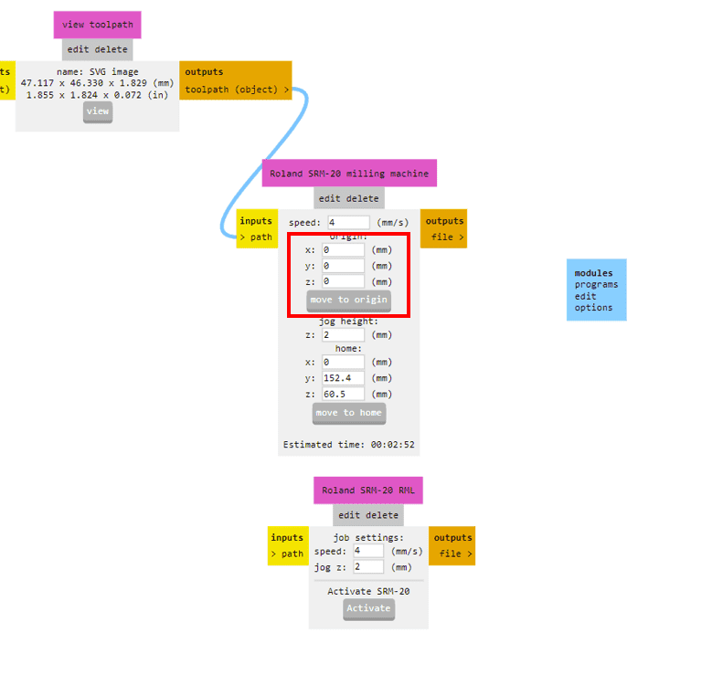
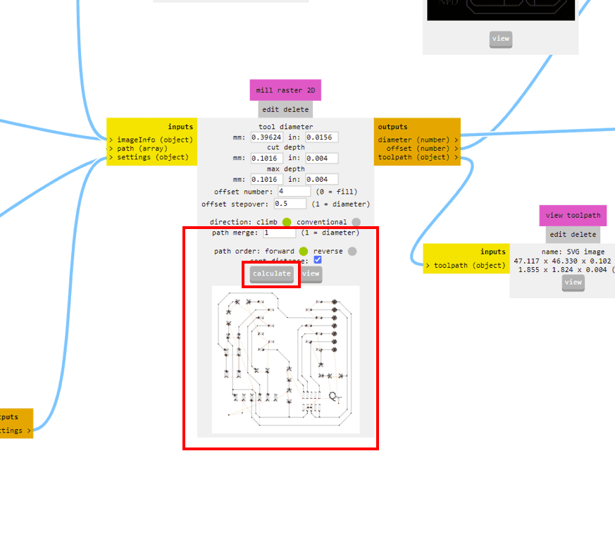
After calculating the path, it will take us to a different tab which shows us the toolpath preview of the board. This is very helpful as we can detect the possible errors in the milling such as joining of different routes and others.
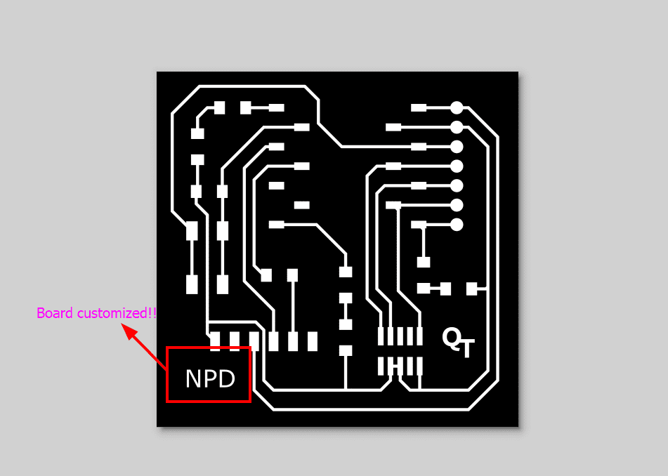
I customized my board in Inkscape and here you can see the results!!!

Soldering is a method which is made use of to link steel elements whether for mechanical or electric objectives. It includes heating a reduced melting factor steel alloy, referred to as solder, which is after that related to the steel components to produce a bond upon strengthening.
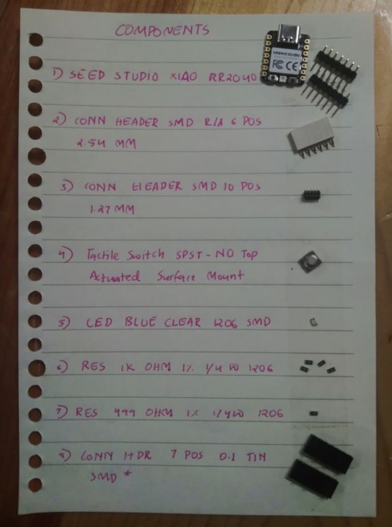
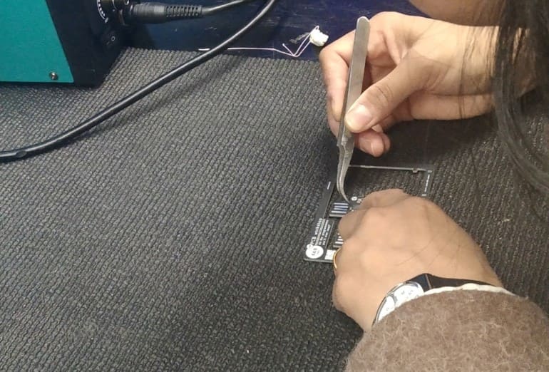
Before soldering, I assembled all the components on a piece of paper alongside their names to make it easier for soldering and also to ensure that all the components were present.
Step 1: Prepare PCB
Clean the PCB board if needed and ensure it's free from dust or debris. Place it securely on a heat-resistant surface.
Step 2: Heat Soldering Iron
Let the soldering iron heat up to the appropriate temperature for soldering which I kept roughly between 600°- 650°F.
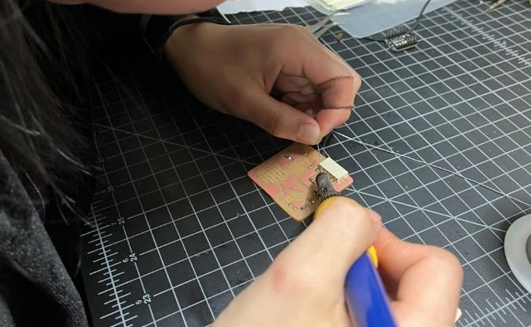
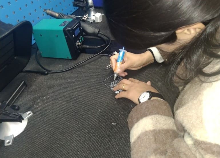
Step 3: Solder Components
Place the component leads on their respective place on the PCB board. Heat the solder pad and component lead simultaneously with the soldering iron, then apply solder to form a good joint.
Make sure to keep your soldering iron tip clean and free of oxidation (by cleaning it on a wet sponge or brass wool ball)
Step 4: Test Connections
After soldering all components, perform continuity tests with multimeters or power up the circuit to verify proper connections and functionality.
To begin, the PCB need to be separated from any kind of power resource. The multimeter is readied to connection setting where it produces a noise or reveals connection with a reduced resistance analysis when a circuit is total. One probe is positioned on a factor (like an element pin or PCB trace) plus the various other probe is positioned on the 2nd indicate examine connection. If there's a continual course, the multimeter suggests connection; or else, it reveals a high resistance. This examination assists determine breaks, shorts or defective links in the PCB's wiring aiding in repairing along with making certain appropriate performance.
Here is my soldering video!!
In Adrian's Documentation, he has given how we can use the QT board as a "hello board" or as a programmer. So to use the QT board as a hello board there were steps for uploading a blink program on the board and I took reference from there to upload the blink program.
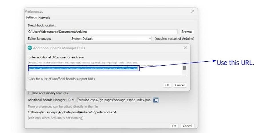
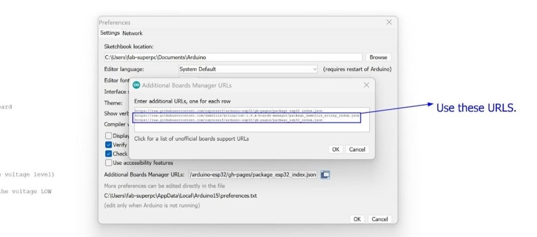
Step 1: Open the Arduino Program
First, navigate to File->Preferences. Here, add the URL for additional boards like Arduino-Pico by Earlephilhower.
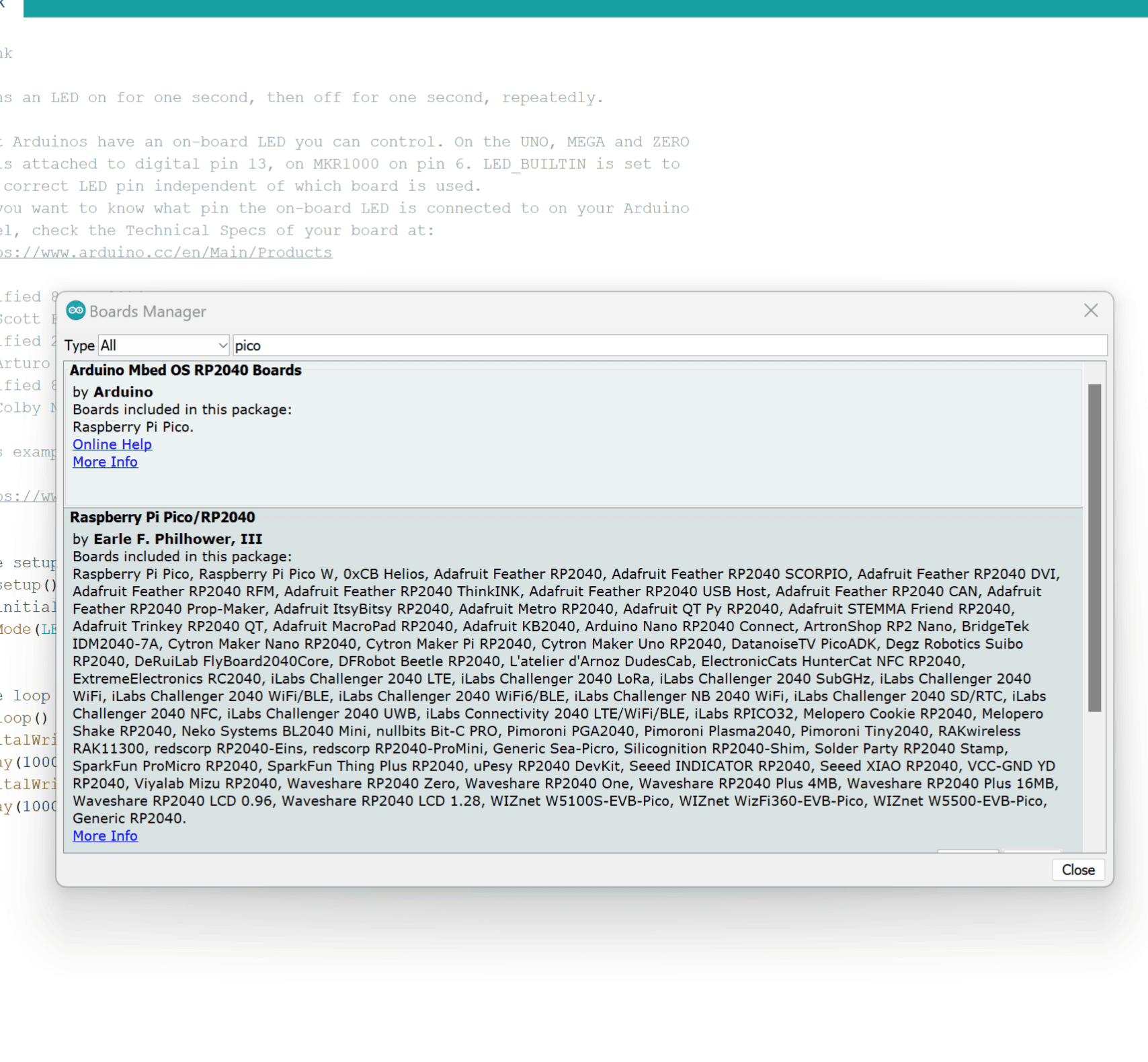
Step 2: Access Boards Manager
Next, go to Tools->Board->Board Manager. Download the Pico board from here.
Step 3: Configure for Seeed Studio XIAO RP2040
Configure the Arduino IDE for the Seeed Studio XIAO RP2040. Look for the device in the COM port, such as COM 3.
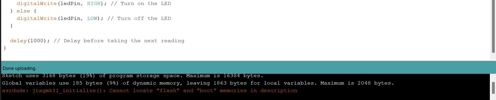
Step 4: Load the Blink Program
Load the Blink program to activate the LED on pin 26 (GPIO 26). Upon uploading, all relevant details will show up in the notifications section.
Here is the video of the blinking LED after I have uploaded the blink program
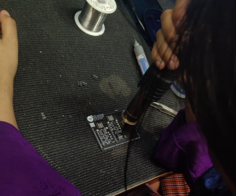
Last week, our group visited the Jigme Namgyel Wangchuck Super Fab Lab and there, we were introduced to reflow soldering by madam Wangzom
Reflow soldering is a technique in electronic devices setting up where solder paste a mix of solder as well as change is put on published motherboard. Parts are placed on home plate paste-coated pads as well as a warmth weapon is utilized to warm the setting up thawing the solder as well as creating links in between the parts along with the board.
We set the temperature of the heat gun as 302 degrees Fahrenheit.
You can find my Electronics Glossary page here. I made this page for my future reference and to help others referring to my documentation as well.