Week 14 - Interface and Application Programming

Group Assignment:

  • Compare as many tool options as possible

  • Group Assignment Link:

  • Click HERE to view Group Assignment Page!
  • ____________

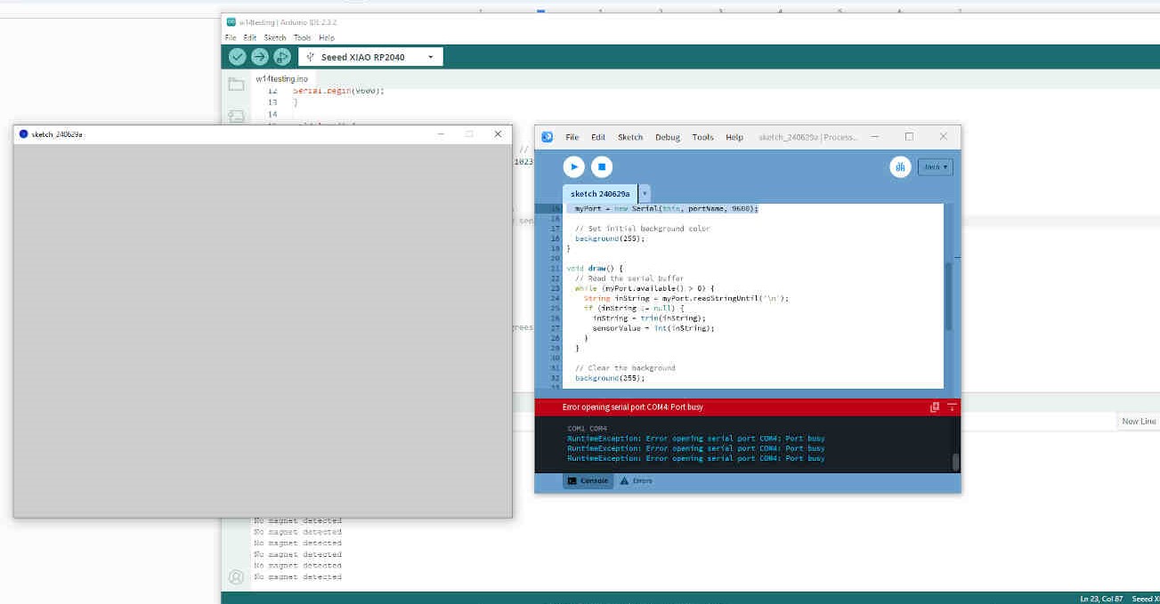
    The tools we explored were Processing IDE and Arduino IDE

    ____________


    Individual Assignment:

  • Write an application that interfaces a user with an input &/or output device that you made

  • ____________

    Research and Planning

    This week is all about designing data readers to create interesting patterns and graphics on the web as a response to the inputs we make on our circuit boards.

    Oscar recommended I try out “Processing” as it is the most user friendly option. Neil recommended “Node-Red” and “Modsproject” to create data visualizations. I can either use my ESP32-C3 hello.button.blink board or my Seeed Studio Xiao RP2040 then I could use Modsproject to create patterns during data reads. His example showed a HTML webpage with buttons to “Turn LED On/Off”, along with a reader that lets you know whenever the PCB Button is being pushed, which seems easy enough.

    1

    Neil also recommended learning Python or JavaScript but that's just not gonna happen in the timeframe I have - I'll be aiming for something user-friendly, simple & visual. Node Red + Modsproject seemed like a very possible process, though I wanted to check in with Global Open Time to weigh my options.

    During Global Open Time Rico recommended Arduino Cloud as a newer software to try out. Adrian guided me through how he used a Time of Flight sensor with Processor and recommended that I follow this strategy (but change elements) as it will not only complete the Networking and Applications assignment - but also the Input Devices week.

    1

    EDITORS NOTE: A lot of the 'Time of Flight' debugging done during this week allowed me to revisit the issues found in Week 11 - Input Devices, so some similarities in Debugging documentation may occur.

    EDITORS NOTE 2: A lot of debugging was done this week for the VL53L1X Time of Flight sensor, parts of which had been implemented into Week 11 - Output Devices. However upon reviewing documentation, along with deciding to move forward with the Hall Effect Sensor for this week, I have since removed all documentation of VL53L1X from Week 14 to avoid confusing/clashing assignment pages. Info regarding the VL53L1X Time of Flight sensor can be found by following this link to Week 11 - Input Devices.

  • ToF Sensor - Adrian Example

  • __________


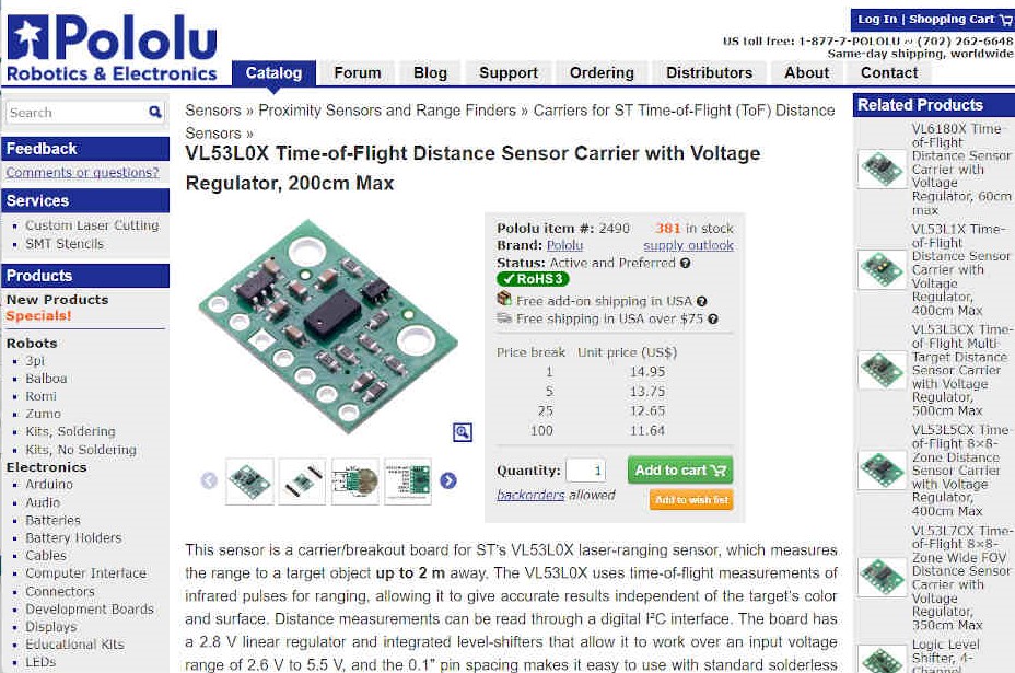
    Major Update: The ‘VL53L1X Time of Flight’ sensor was recommended to me as it's supposedly one of the easiest sensors to get working. Whereas my experience differed highly. After tons of debugging and trying to fix issues that shouldn't have been there, my final thoughts on the VL53L1X is that it's highly unreliable.

    1

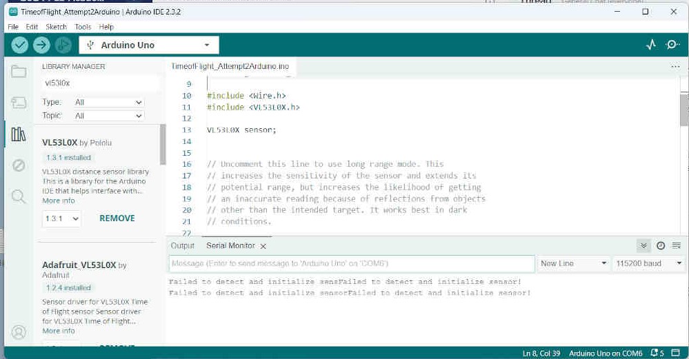
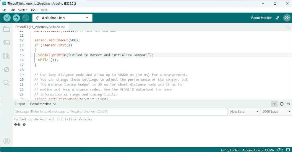
    Even when I finally got it working on my computer, it stopped working when I returned to it a week later - with everything still as it should be, and yet it consistently “Failed to Detect Sensor”. Myself, my local instructors and Global Open Time instructors couldn't find the issue. We only had access to 2x Time of Flight sensors in our FabLab and the 2 I had seemed faulty or defective.

    Although I considered the VL53L1X to be the exact sensor I needed for my final project, I ultimately made the decision to change sensors for my final project due to how unreliable the Time of Flight sensor was.

    1

    During a Global Open Time, the “Hall Effect” sensor was recommended to me as it is one of the easiest sensors to get working and doesn't even need a library for the code to work. Although I have already made so many concessions towards my final project, I know the most important thing for my presentation is to
    “make something that WORKS”.

    So for this Week 14 assignment, I will be proceeding forward with a 'Hall Effect Sensor'.

    ____________


    Hall Effect Sensor

    Hall Effect Component Description

    (As described by ChatGPT V.4o, June 19th 2024)

    A Hall effect sensor is a device that detects the presence and strength of a magnetic field using the Hall effect principle. This principle, discovered by Edwin Hall in 1879, states that when a current-carrying conductor is placed in a perpendicular magnetic field, a voltage (the Hall voltage) is generated across the conductor. The sensor consists of a thin semiconductor material, a constant current source, and a signal conditioning circuit to amplify the Hall voltage, which is proportional to the magnetic field strength.

    Hall effect sensors are used in various applications, including position and speed sensing in automotive systems, current sensing in power supplies, and proximity sensing in industrial equipment. They offer advantages such as non-contact operation, durability, and linear output, though they can be sensitive to temperature changes and have a limited range for detecting magnetic field strengths.

    Hall Effect Code (used for Final Project's "Acknowledgement Animation")


    #include < Servo.h >

    const int hallPin = 7; // Hall effect sensor output pin
    const int servoPin = 4; // Servo control pin
    Servo myservo;
    int sensorState = 0;

    void setup() {
    pinMode(hallPin, INPUT_PULLUP);
    myservo.attach(servoPin);
    myservo.write(0); // Initial position
    Serial.begin(9600);
    }

    void loop() {
    sensorState = digitalRead(hallPin);
    if (sensorState == LOW) {
    myservo.write(90); // Move servo to 90 degrees
    Serial.println("Magnet detected");
    delay(1500);
    myservo.write(130);
    delay(500);
    myservo.write(90);
    delay(4500);
    } else {
    myservo.write(0); // Move servo back to 0 degrees
    Serial.println("No magnet detected");
    }
    delay(100); // Debounce delay
    }


    Processor Code for reading Hall Effect sensor

    (Sourced through ChatGPT v.4o, 19th June 2024)

    First, make sure you have Processing installed from Processing's official website.

    Open Processing and create a new sketch. Use the following code to read the sensor values sent from the Arduino and create a graphical representation:import processing.serial.*;

    import processing.serial.*;

    Serial myPort; // The serial port
    int sensorValue; // Value read from the sensor

    void setup() {
    // Set the window size
    size(800, 600);

    // List all the available serial ports
    println(Serial.list());

    // Open the port you are using at the same speed as the Arduino
    String portName = Serial.list()[0]; // Adjust based on your port
    myPort = new Serial(this, portName, 9600);

    // Set initial background color
    background(255);
    }

    void draw() {
    // Read the serial buffer
    while (myPort.available() > 0) {
    String inString = myPort.readStringUntil('\n');
    if (inString != null) {
    inString = trim(inString);
    sensorValue = int(inString);
    }
    }

    // Map the sensor value to a vertical position for the graph
    float y = map(sensorValue, 0, 1023, height, 0);

    // Draw the graph
    stroke(0);
    line(frameCount % width, height, frameCount % width, y);

    // Clear the background periodically
    if (frameCount % width == 0) {
    background(255);
    }
    }

    Processing Code Explanation:

    Setup Function:
    size(800, 600) sets the size of the window.
    Serial.list() lists all available serial ports.
    new Serial(this, portName, 9600) opens the specified serial port.
    background(255) sets the initial background to white.

    Draw Function:
    Reads data from the serial buffer.
    Maps the sensor value to a vertical position.
    Draws a line based on the sensor value.
    Clears the background periodically to avoid clutter.

    This setup will create a dynamic graph that visually represents the Hall effect sensor readings in real-time. Adjust the portName in the Processing code to match the correct serial port for your Arduino.

    ____________


    Completing the Assignment

    Processing Interface for Output Device


    During my experimentation with the Hall Effect sensor, I failed to produce any worthwhile Processing interface as the implementation of the code was faulty. The majority of attempts using Processing ended up with a Blank or Crashed Sketch. Eventually I discovered i inputted the incorrect 'Serial.list();' resulting in Processing trying to Access the incorrect COM Port. Thought the issues with Hall Effect reading continued...

    1

    The Arduino IDE Serial Monitor was able to send readings of the hall effect sensor, and it was working perfectly fine, but when trying to read the sensor data in Processing, it wasn’t able to change from “Sensor Value: 0”. After much debugging, I had decided it’s time to go simple. Taking advantage of this week’s assignment being “Write an application interface for an Input and/or Output device”, I decided to focus on just getting a servo working with both programs, then seeing what can be expanded upon in Processing.

    Below you can find the code I used for completing this assignment...

    NOTE: The code used for Processing and Arduino was sourced through ChatGPTv.4o on the 29th of June 2024. It was experimented with and adapted through trial and error. Also be sure to remove the spaces between ‘< Servo.h >’ for the Arduino IDE Code as they were added to help them become visible through Visual Studio Code.

    _____________


    Arduino IDE Code

    Sourced through ChatGPTv.4o and Adapted on the 29th of June 2024

    #include < Servo.h >

    Servo myServo; // Create a servo object
    int servoPin = 9; // Servo control pin
    int pos = 0; // Variable to store the servo position

    void setup() {
    myServo.attach(servoPin); // Attach the servo to pin 9
    Serial.begin(9600); // Start serial communication at 9600 bps
    }

    void loop() {
    for (pos = 0; pos <= 180; pos += 1) { // Sweep from 0 to 180 degrees
    myServo.write(pos); // Tell servo to go to position in variable 'pos'
    Serial.println(pos); // Send position value to serial
    delay(15); // Wait for the servo to reach the position
    }
    for (pos = 180; pos >= 0; pos -= 1) { // Sweep from 180 to 0 degrees
    myServo.write(pos); // Tell servo to go to position in variable 'pos'
    Serial.println(pos); // Send position value to serial
    delay(15); // Wait for the servo to reach the position
    }
    }


    _____________


    Processing Code

    Sourced through ChatGPTv.4o and Adapted on the 29th of June 2024

    import processing.serial.*;

    Serial myPort; // The serial port
    int servoPos; // Variable to store the servo position

    void setup() {
    // Set the window size
    size(800, 600);

    // List all the available serial ports
    println(Serial.list());

    // Open the port you are using at the same speed as the Arduino
    String portName = Serial.list()[0]; // Replace with the correct index
    myPort = new Serial(this, portName, 9600);

    // Set initial background color
    background(255);
    }

    void draw() {
    // Read the serial buffer
    while (myPort.available() > 0) {
    String inString = myPort.readStringUntil('\n');
    if (inString != null) {
    inString = trim(inString);
    servoPos = int(inString);
    }
    }

    // Clear the background
    background(255);

    // Map the servo position to a graphical position
    float x = map(servoPos, 0, 180, 0, width);

    // Draw the servo position
    fill(0);
    ellipse(x, height / 2, 50, 50); // Draw a circle representing the servo position

    // Draw the position value
    textSize(32);
    textAlign(CENTER);
    fill(0);
    text("Servo Position: " + servoPos, width / 2, height - 30);
    }


    NOTE: Make sure to change the “Serial.list()[0];” to the appropriate port. The ‘0’ represents the first port available. The code itself allows you to see which of your ‘COM’ ports are available. The correct COM port for my setup was ‘COM4’ and it was the second port available so I had to change it to ‘Serial.list()[1];’.


    _____________


    I was relieved to see the Processing Sketch actually reading my Servo Motor’s position and displaying it on the interface. Technically I could have just stopped there but the interface that was written was bare-bones and depressingly boring. Thankfully, now that the connections are no longer the problem, I can implement something a lot more visually appealing and easier to read for data. The best part about embedded coding is the advantages of copying and pasting work that others have already done and being able to improve upon it or change to suit your own needs. Now that everything is functional on my end, I’m free to experiment!

    …Unfortunately the Fab Academy deadline is fast approaching and I don’t have the luxury of time to spend experimenting. So instead I went back to ChatGPT to see if it can “expand on the code to make the data read look much ’cooler’”. This was also to see how reasonable the ChatGPT AI can respond to the request of something ‘affectionately pleasing’. The result won’t win any Oscars but it absolutely gave me a more visually stimulating interface that is much easier to read. I’m impressed by current commercial AI once again.

    Updated Processing Code

    Sourced through ChatGPTv.4o on the 29th of June 2024

    import processing.serial.*;

    Serial myPort; // The serial port
    int servoPos; // Variable to store the servo position
    float displayPos; // Variable to store the displayed position

    void setup() {
    // Set the window size
    size(800, 600);

    // List all the available serial ports
    println(Serial.list());

    // Open the port you are using at the same speed as the Arduino
    String portName = Serial.list()[0]; // Replace with the correct index
    myPort = new Serial(this, portName, 9600);

    // Set initial background color
    background(255);

    // Initialize display position
    displayPos = 0;
    }

    void draw() {
    // Read the serial buffer
    while (myPort.available() > 0) {
    String inString = myPort.readStringUntil('\n');
    if (inString != null) {
    inString = trim(inString);
    servoPos = int(inString);
    }
    }

    // Smoothly transition the displayed position
    displayPos = lerp(displayPos, servoPos, 0.1);

    // Clear the background with a gradient
    for (int i = 0; i < height; i++) {
    stroke(map(i, 0, height, 255, 200), map(i, 0, height, 255, 230), map(i, 0, height, 255, 255));
    line(0, i, width, i);
    }

    // Map the servo position to a graphical position
    float x = map(displayPos, 0, 180, 100, width - 100);

    // Draw a fancy circle for the servo position
    noStroke();
    fill(50, 150, 255, 150);
    ellipse(x, height / 2, 100, 100); // Outer circle
    fill(50, 150, 255);
    ellipse(x, height / 2, 80, 80); // Inner circle

    // Draw the position value with a shadow
    textSize(32);
    textAlign(CENTER);
    fill(50, 150, 255, 150);
    text("Servo Position: " + nf(displayPos, 1, 2), width / 2 + 2, height - 32 + 2);
    fill(0);
    text("Servo Position: " + nf(displayPos, 1, 2), width / 2, height - 32);
    }

    _____________


    As you can see from the Video Section below, I was able to Write an Application Interface that is able to read and display the sensor value of my Servo Motor. The Board I used to create this communication was designed and produced for my Final Project and uses a Seeed Studio Xiao RP2040 MicroController. The files can be found in the Project Files Zip Folder at the bottom of my Final Project Page. The MicroController was embedded with C++ code in Arduino IDE, then used in conjunction with Processing (using Java Code) to design an application interface that reads the Servo Motor’s sensor Value.
    With that, I call this Assignment Complete!

    _____________


    VIDEO SECTION

    Processing Success! (Simplistic Servo Read)


    Advanced Servo Data Read Interface


    Advanced Servo Data Read Interface (Short)


    Returning Fuctionality to my Final Project


    ____________


    Conclusion / Reflection

    Similarly to last week's assignment, this week's Programming assignment came at a time where many of my unsuccessful assignments started snowballing into each other and I was flying into a panic that I wouldn't be able to succeed in my Fab Academy journey - which added a ton of pressure for disappointing myself and those around me.

    HOWEVER! Thankfully I have some very minor experience with Processing and what this assignment asks of me. This did take some of the pressure off, but admittedly I kept brushing it aside when focusing on more complicated assignments. Once I returned, I felt anxious that it wouldn't work as smoothly as I would hope for, but it indeed went nearly as smoothly as I hoped - but not without making some mistakes along the way.

    1st mistake: I wanted to use the Hall Effect board that I used for my “Little Buddy” Final Project so that I can monitor the Hall Effect Sensor & my Servo Motor while also having it attached to my Little Buddy Model, but doing this without detaching my model from the board was a mistake as it caused my model to have sudden collision problems during testing. After I separated the model, I spent a lot of time trying to read the Hall Monitor through Processing, but while I got accurate readings from the serial monitor, Processing was unable to accurately depict the reading - often crashing when I viewed the Sketch I wrote.

    This led me back to Arduino IDE where I focused entirely on just making the Servo Motor Readable. At this point things went very smoothly and ChatGPT’s servo code seemed a lot more reliable & recognizable - even giving full descriptions of what each line of code does. Once I got the basics done and working functionally, I felt a lot more freedom in making the Processing sketch interesting to look at. Now that I got the basics functioning properly, I feel there's a lot more time for growth and learning in this process. I have my uses for making a readable interface based on inputs/outputs so I'll be sure to return at some point.

    The good news is that I finally believe it's possible to succeed in this course! \(^w^)/


    ____________


    Week 14 Project Files

    Week 14 - Project Zip Folder