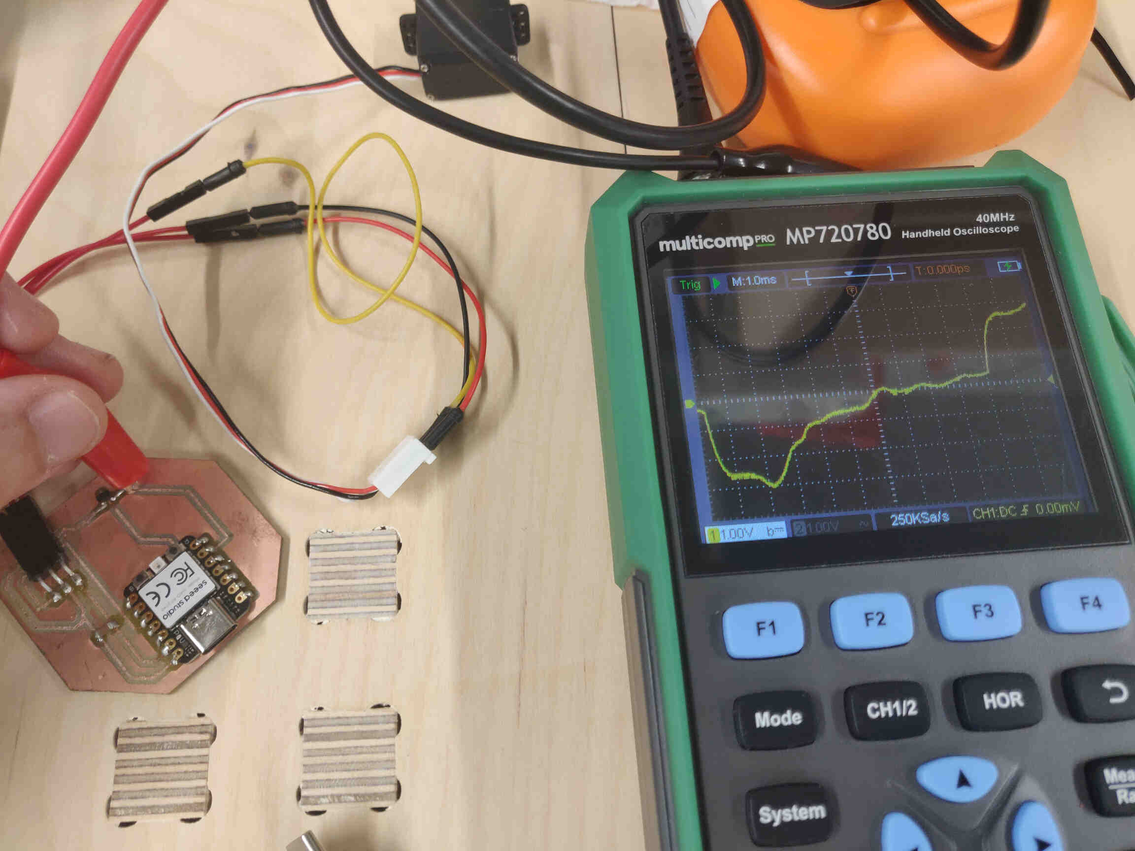
Using Channel 1 on the Handheld Multicomp Oscilloscope, and set to DC Coupling Mode, I was able to examine the Wavelengths of the Hall Effect Sensor while they were Inactive & Active.
Oscilloscope: Hall Effect Signal Connection while inactive:
Wavelength stabilised at Verticle Scale 1.00Volts, Vertical Position 0.00div
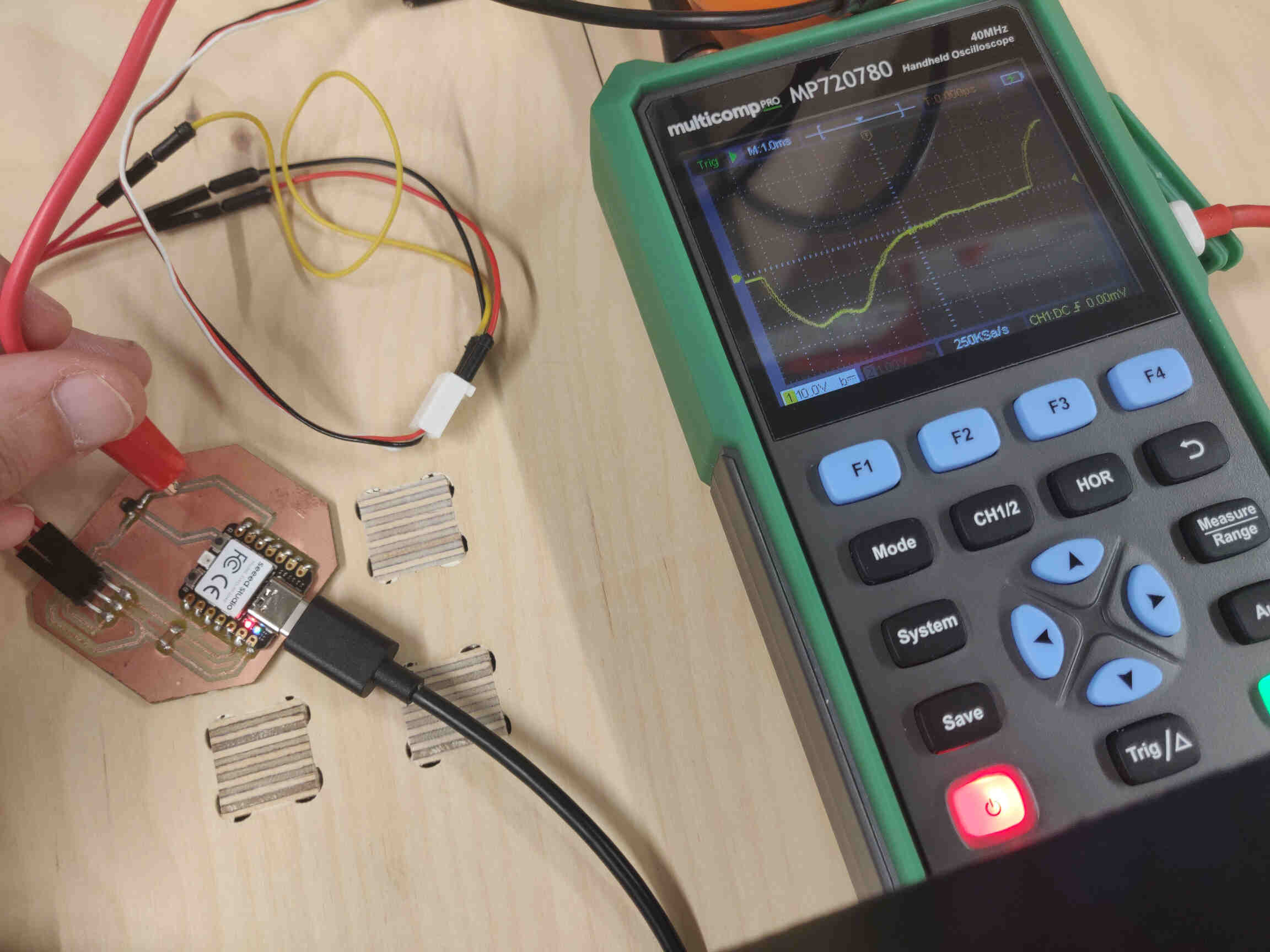
Oscilloscope: Hall Effect Signal Connection while active:
Wavelength stabilised at Verticle Scale 10.0volts, Vertical Position 0.00div
Measure something: add a sensor to a microcontroller board that you have designed and read it
____________
This week’s mission: Try Motion Sensors -> Activate a set Servo Motion
Research: Light sensor might be better? Or Motion Senser - Doppler? Doppler can recognize when something is / isn’t moving. Might be funny to have Final Project activate when the user moves / enters / exits.
Previous experiences with Input devices:
For Output week I was attempting to control a servo motor with a potentiometer with varying success. For Machine Design week, we managed to get a potentiometer to have full rotational control of a servo which we then connected to a platform and gear system.
You can see our progress from HERE.
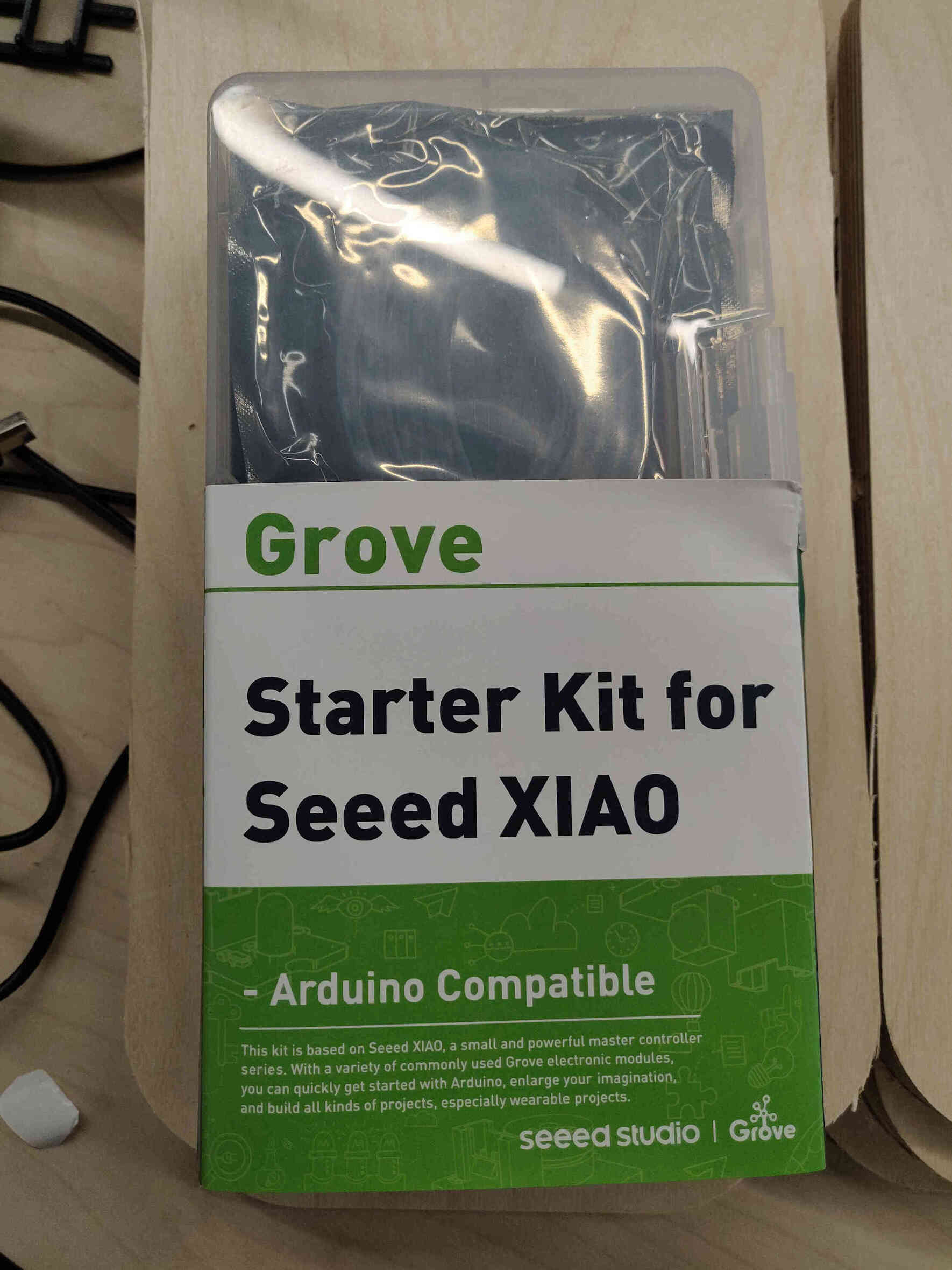
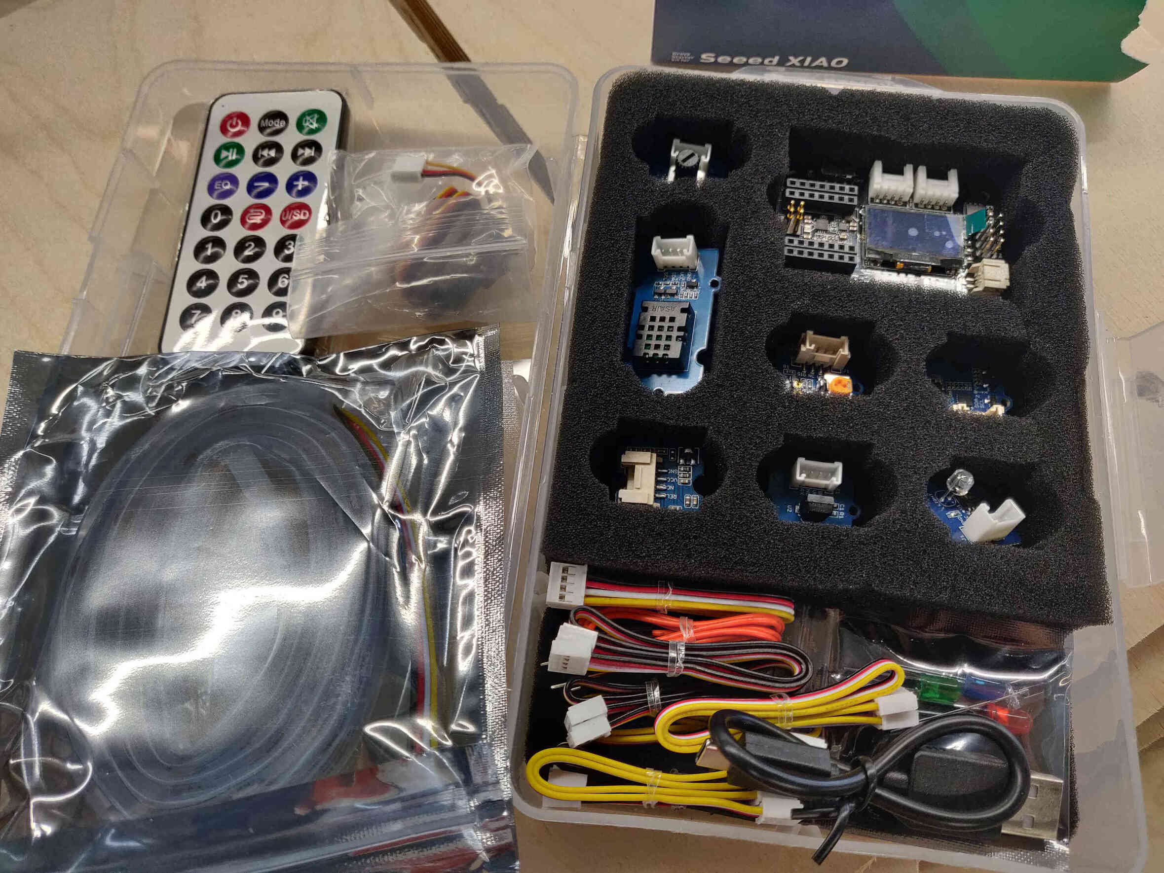
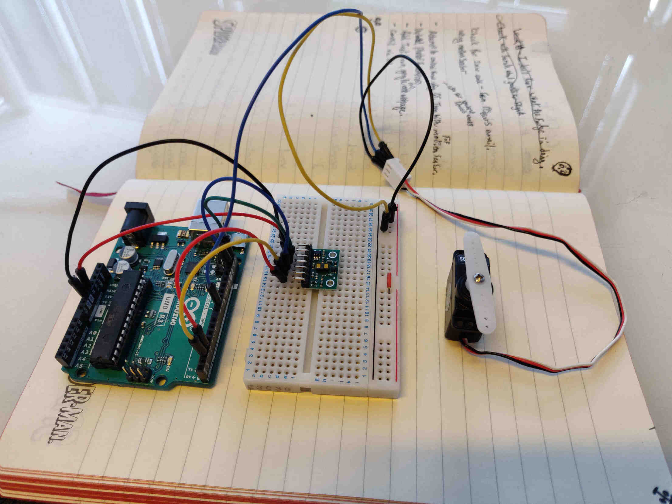
Oscar started me off by giving me a Seeed Studio Xiao RP2040 Starter Kit and asked me to double down on learning the basic processes. I also took stock of what components I needed. Originally I was looking for a SR501 Motion Sensor but there wasn't one in stock so I started off with the "VL53L1X Time of Flight” sensor. The Seeed Studio Starter Kit comes with a Mini PIR Motion Sensor, so that may come in handy at some point.
____________
Progress with Seeed Studio Xiao Starter Kit:
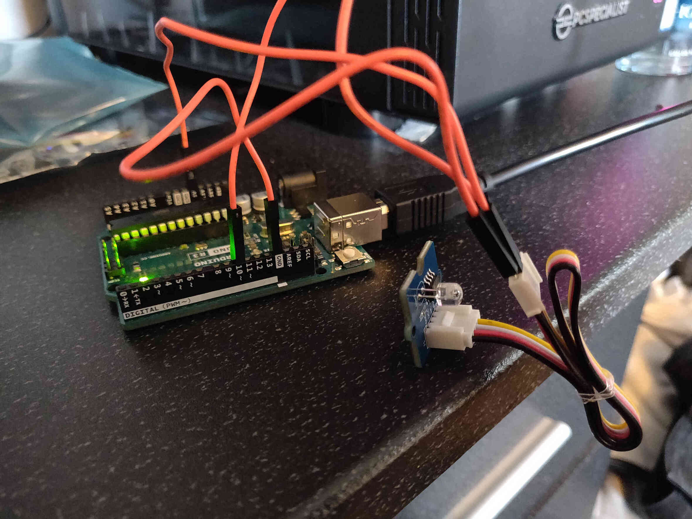
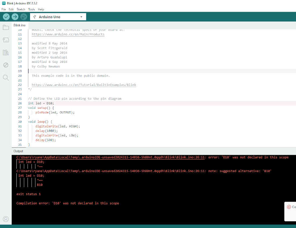
I familiarized myself with the hardware from a visual standpoint but that’s about it. I had no Seeed Studio Xiao with me (since I thought the starter kit came with one), so I tried connecting the Arduino Uno to an external LED but no success. Without supervision on electronics or programming, I’m utterly hopeless.
I ultimately decided in terms of time management and keeping my spirits high, I would focus entirely on completing the assignment rather than learning from scratch how to program these boards and components. I don’t struggle too much with electronic design, production or programming - but it’s the electronic connections and debugging that throw me off entirely.
____________
Week 11 Research - What are Inputs and Outputs?
Inputs:An input device is any piece of hardware that allows us to send data to a computer. (Keyboards, dials, touchscreen, button, etc) Outputs: An Output device is any piece of hardware that allows a computer to communicate information to us. (Screen monitor, speakers, headphones, Printers, etc.)
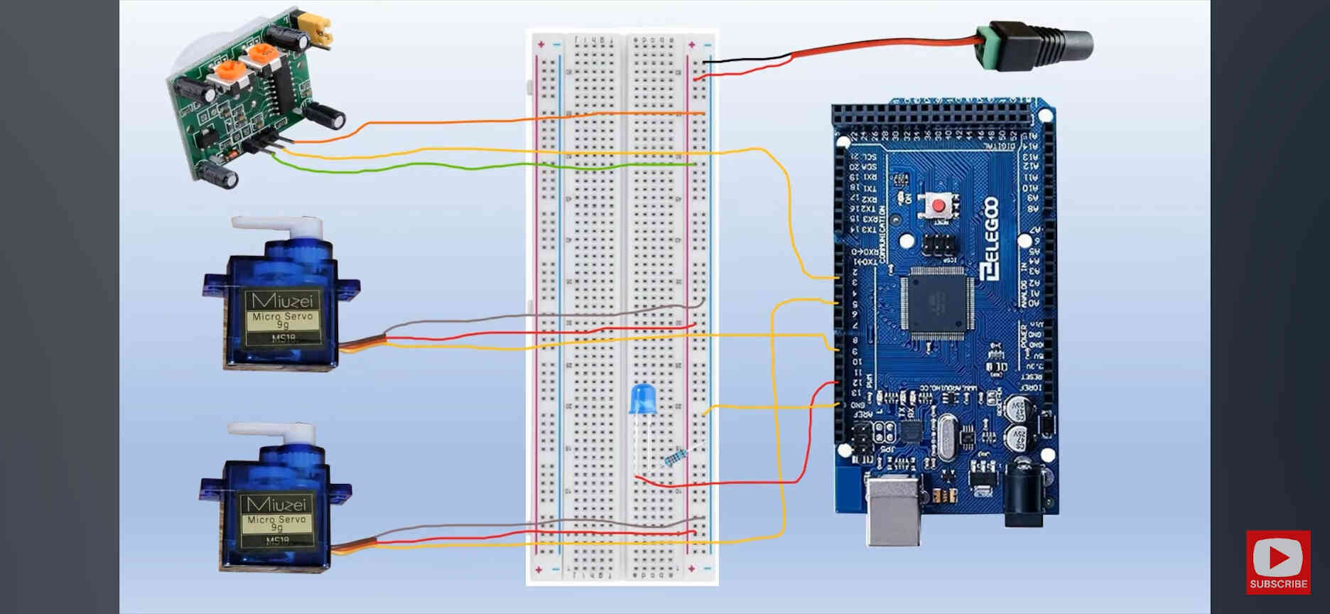
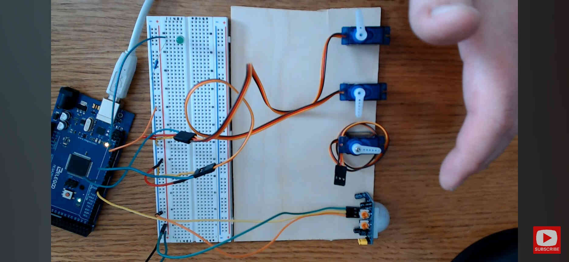
Example of a Motion Sensor activating 2 servo motors (in different directions).
This test example is pretty much what i need to accomplish for my own final project - with the difference being that I need them to move in the same direction, which is an easy change. NOTE: Later on I decided I would only need to control one servo motor for the neck.
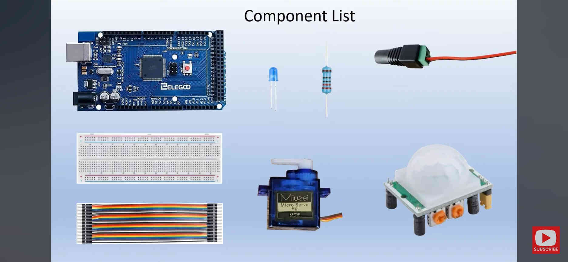
Components needed:
- Arduino UNO / Elegoo Mega
- Breadboard
- M/M Wires / M/F Wires.
- 5mm LED
- 220 ohm resistor
- 5v Power Supply
- 2x Micro Servos
- Hc SR501 IR Motion Sensor
When searching for the 220 ohm resistor, my instructor Oscar explained that the colour bands on the resistors aren’t just for show. He directed me to this website: ‘resistor colour code calculator’ - thanks to which I was able to confirm my resistor without its original packaging.
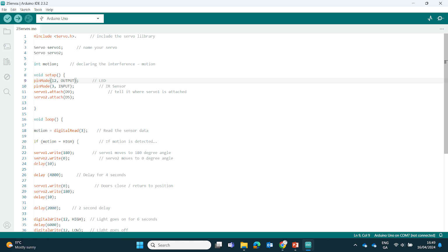
Code Needed for controlling two servo motors:
#include < Servo.h > // include the servo library
servo servo1; // name your servo
servo servo2;
int motion; // declaring the interference - motion
void setup() {
pinMode (12, OUTPUT); // LED
pinMode (3, INPUT); // IR Sensor
servo1.attach (9); // tell it where servo1 is attached
servo2.attach (5);
}
void loop() {
motion = digitalRead(3); // Read the sensor data
if (motion = HIGH); // If motion is detected….
servo1.write(180); // servo1 moves to 180 degree angle
servo.write(0); // servo2 moves to 0 degree angle
delay(10);
delay (4000); // Delay for 4 seconds
servo1.write(0); // Doors close / return to position
servo2.write(180);
delay(10);
delay(2000); // 2 second delay
digitalWrite(12, HIGH); // Light goes on for 6 seconds
delay(6000);
digitalWrite(12, LOW); // Light goes off
delay(2000); // 2 second delay
servo1.write(180); // Doors open
servo2.write(0);
delay(10);
delay(4000); // 4 second delay
servo1.write(0); // Doors close
servo2.write(180);
delay(10);
} else { // If motion ISN’T detected
digitalWrite(12, LOW); // Light will stay off
servo1.write(0); // Doors will stay closed
servo2.write(180);
delay(15);
}
Results:
With a simple change of switching Servo2’s 180s & 0s, I can get both servos turning in the same direction. With that, I can achieve the ‘shoulders’ section of my Final Project.
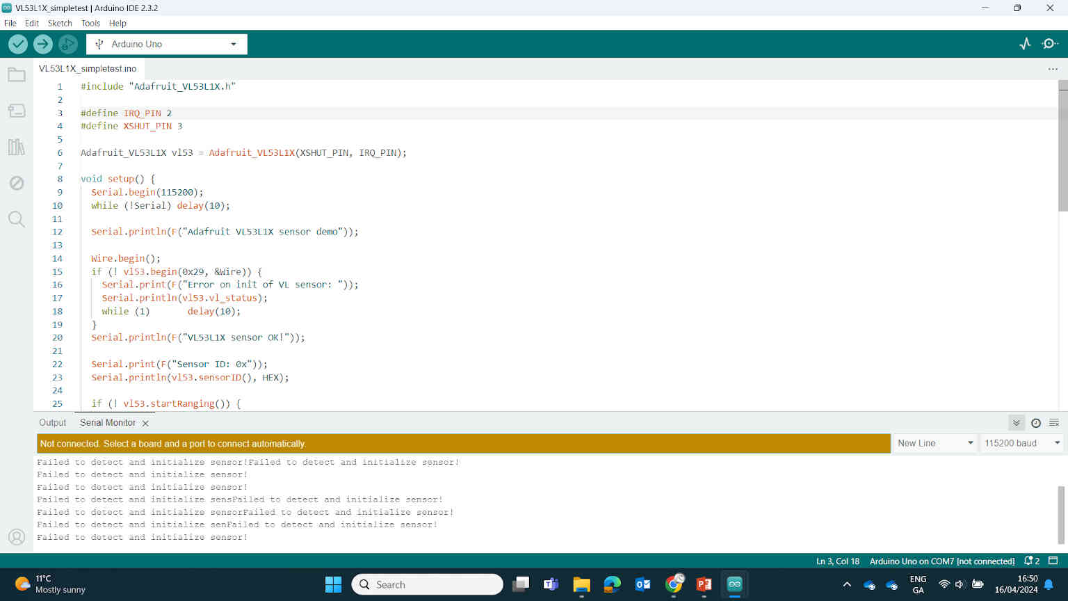
I was able to set this up, though the servos were on a 6 second timer rather than being controlled by the motion sensor. My instructor explained to me what I was doing and the flow of current on the breadboard, as well as how to convert the same diagram over from the Arduino to the Quentorres. Before I moved on to the Quentorres, it was important that I got the motion sensor working. I attempted this by following the Adafruit Time of Flight example ‘VL53L1X_simpletest’. I removed the servo wires and motors and used the Serial Monitor in Arduino IDE to read whether the motion sensor was working.
____________
Example of ‘Time of Flight’ VL53L1X Motion Sensor Code:
if (vl53.dataReady()) {
// new measurement for the taking!
distance = vl53.distance();
if (distance == -1) {
// something went wrong!
Serial.print(F("Couldn't get distance: "));
Serial.println(vl53.vl_status);
return;
}
Serial.print(F("Distance: "));
Serial.print(distance);
Serial.println(" mm");
// data is read out, time for another reading!
vl53.clearInterrupt();
}
}
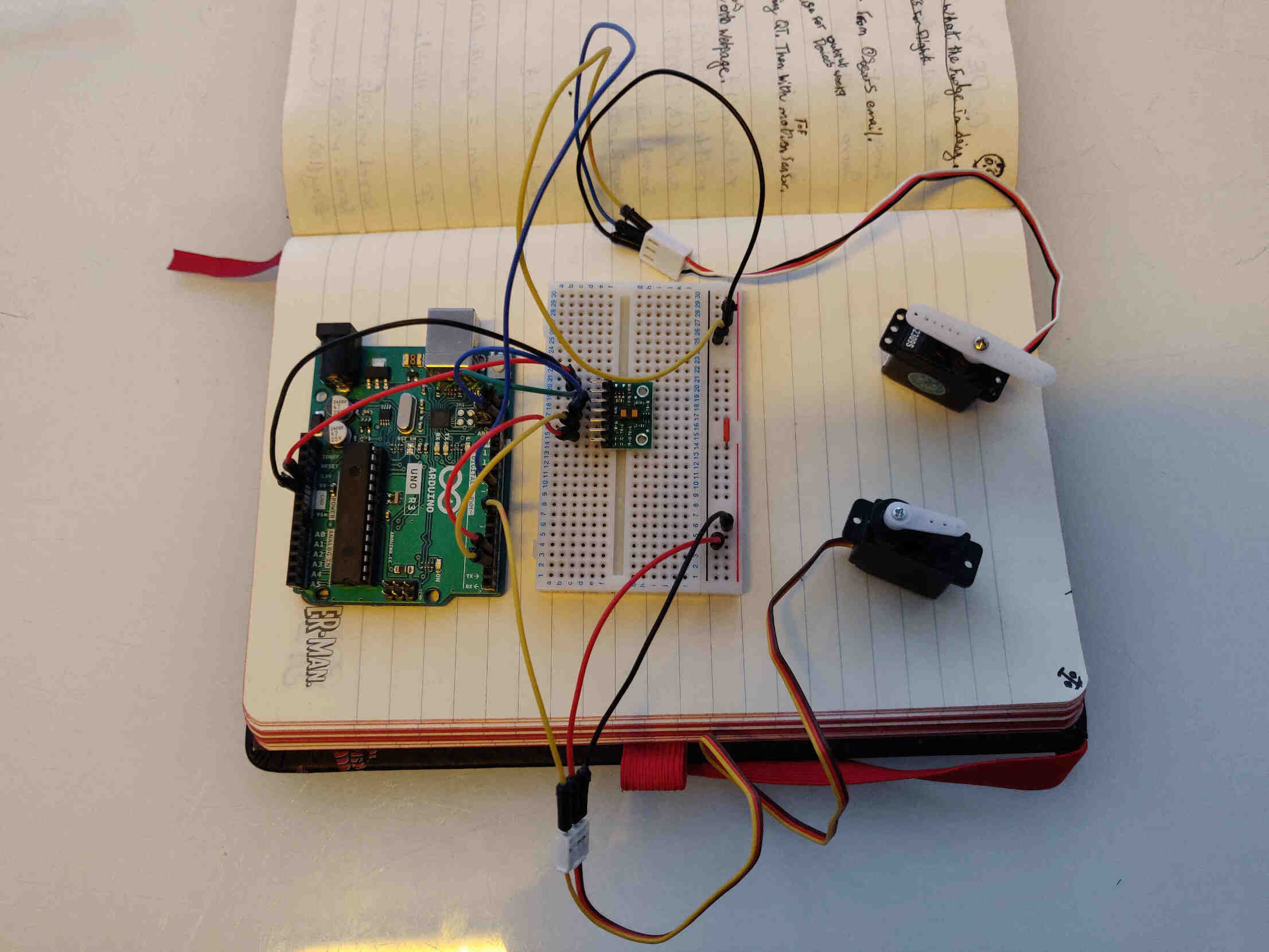
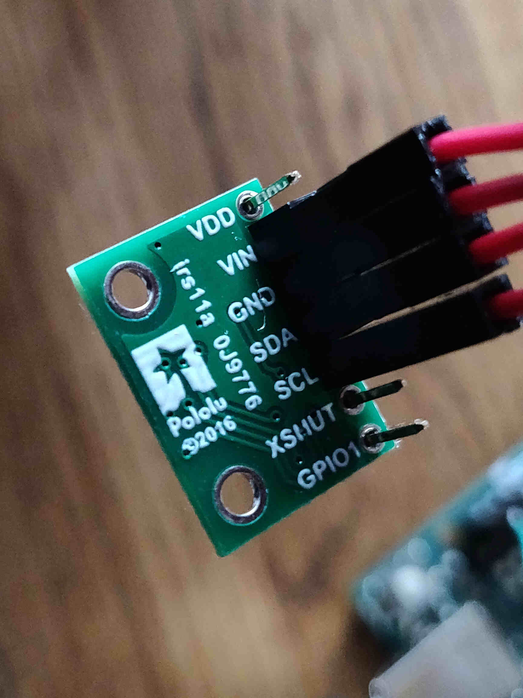
Results: After much testing and checking wires, At the end of the day (before Wednesday's meeting), results were less than satisfactory. According to the Serial Monitor, the code uploaded was fine, but it would only read the first pass and was not able to read anything after that. I have yet to find the solution. I made a few beneficial changes however. At first I noticed that the ToF component I have had their SDA & SCL stations + the GPIO + XSHUT stations swapped - so I rearranged the wires to suit the component board. Also replacing code & making some component/wire positioning changes. Unfortunately, this didn’t change anything.
On the plus side, I left knowing what the possible issue could be. A lot of the code I implemented was missing key factors for motion sensing. Such as the distance it should scan, average lighting settings, etc.
This may have seemed obvious to others but for someone as technically inept as me, the comments in this code awaiting input just seemed like any other code that would be displayed through the serial monitor. That being said, this may not even be the resolution to my motion sensing problem. More testing is needed, datasheet needs to be re-reviewed to the best of my ability and once working, I’ll need to convert and change elements of the code and wiring so that it will work on my own Quentorres. More info is soon to come!
____________
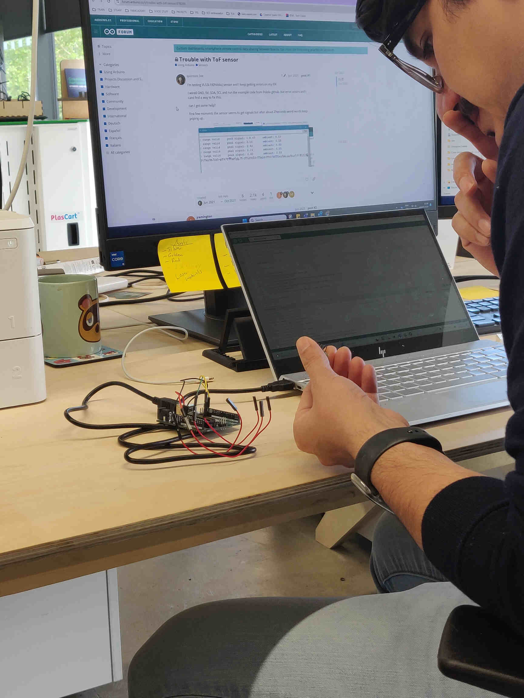
Debugging VL53L1X Time of Flight Sensor:
Trying to follow Adrian's Time of Flight sensor guide and datasheets but I have no idea what I'm doing wrong and as usual I didn't even know where to begin with asking questions. I asked my fellow Mattermost students what the issue may be or if they have any other simple guides on how to set up a Time of Flight VL53L1X with a Seeed Studio Xiao RP2040?
Breaking down the current progress:
I have Xiao RP2040 & VL53L1X boards & libraries downloaded.
No Errors on Uploading but also no response/feedback from the serial monitor.
Voltages seemed okay with Multimeter.
Cables seem fine as far as I can tell.
Serial Monitor set to 115200 Baud.
There were incorrect connections for SDA & SCL, but now that I've put them in properly nothing has changed yet.
I might need to leave the Electronics/Programming assignments until after I finish most of my Final Project. I'm not really getting anywhere on my own. However I was urged by Adrian to push forward as I need this for my Final Project. Tried with 5V and there was no change. I'll continue testing and try different wires + Arduino, etc
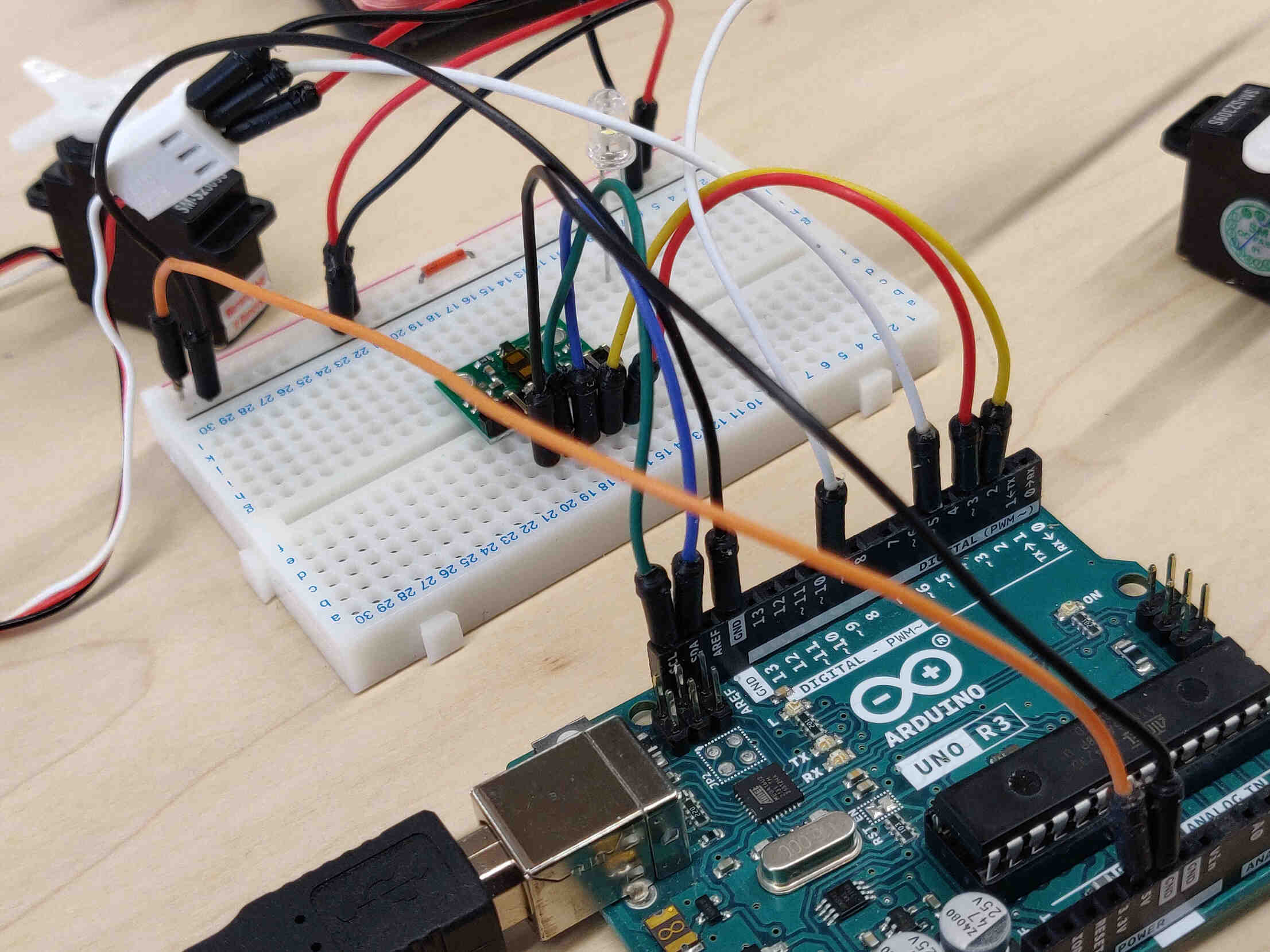
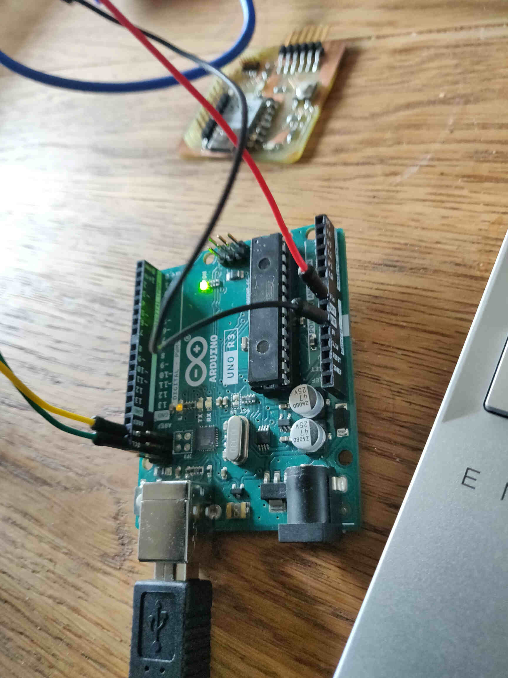
Arduino UNO Testing: With the wiring setup and the libraries downloaded, I attempted to recreate the Time of Flight setup. Not when using Quentorres, but when I use Arduino Uno I get the message in the Serial Monitor:
"Failed to detect and initialize the Sensor!"
"Failed to detect and initialize the Sensor!"
I also researched the components I had and it seems to be a VL53L0X, not a VL53L1X (NOTE: This turned out not to be true) so I swapped around the code. Got a bit further now, Had to update "VL53L0X" library to "Adafruit_VL53L0X" and it got close to working but now I'm having the issue: "class Adafruit_VL53L0X" has no member named 'setTimeout'
I Thought the ‘VL53L0X by Pololu’ library was already downloaded, but it wasn't. The Adafruit_VL53L0X library was the wrong one. The code seems fine now and it was uploaded, but I'm still getting the issue in Serial Monitor:
"Failed to detect and initialize the Sensor!"
"Failed to detect and initialize the Sensor!"
Conclusion: It may be a wiring issue or the sensor that is damaged. I'll try swapping out & messing with the wires. If I can't get it working, I'll be able to go to FabLab on Tuesday to swap components.
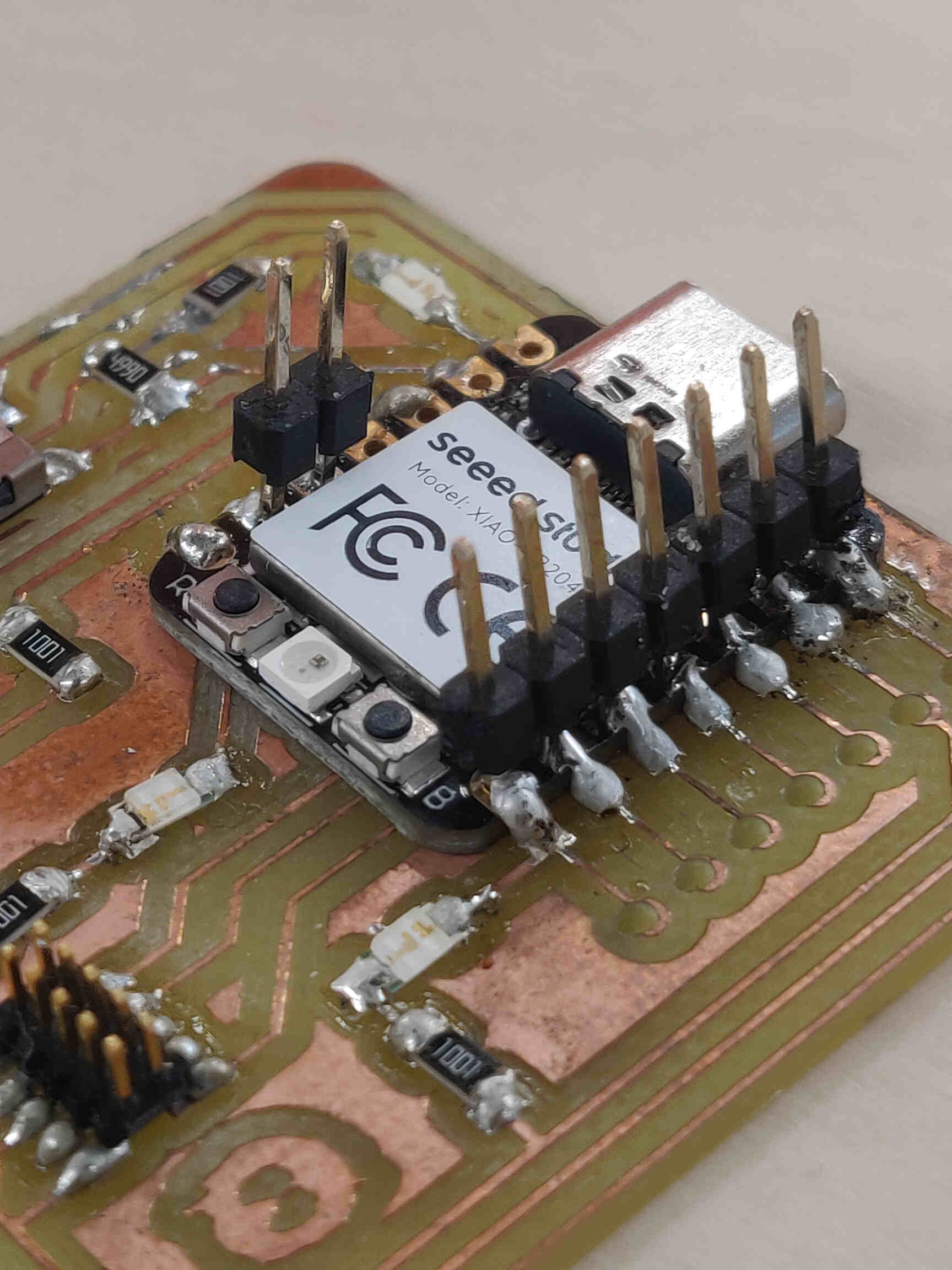
Return to The Fab Lab: First thing we discovered here was that the motion sensor component I was using WAS actually the VL53L1X. The reason why I though otherwise was because I typed in the code behind the component which read “irs11a 0J9776” which led me to the VL53L0X Pololu site, but later I saw the ‘VL53L1X Pololu’ site which contained the EXACT SAME IDENTIFICATION MARKINGS!
Now I needed to re-input the original code and see if I could get further. While I was here, I soldered 2 header pins to the SDA & SCL pin holes on my Quentorress board. After some rearranging of the code, checking datasheets and testing on multiple motion sensor components, I still got the same error:
"Failed to detect and initialize the Sensor!" "Failed to detect and initialize the Sensor!"
I honestly don’t know where to go from here. We tested the same type of Sensor (the only ones we have at the moment), tried on RP2040 and Arduino and still no luck. We soldered the pins, changed wires, etc and nothing worked...
MAJOR UPDATE: We tried it on Oscar's Computer and it worked perfectly fine!!!
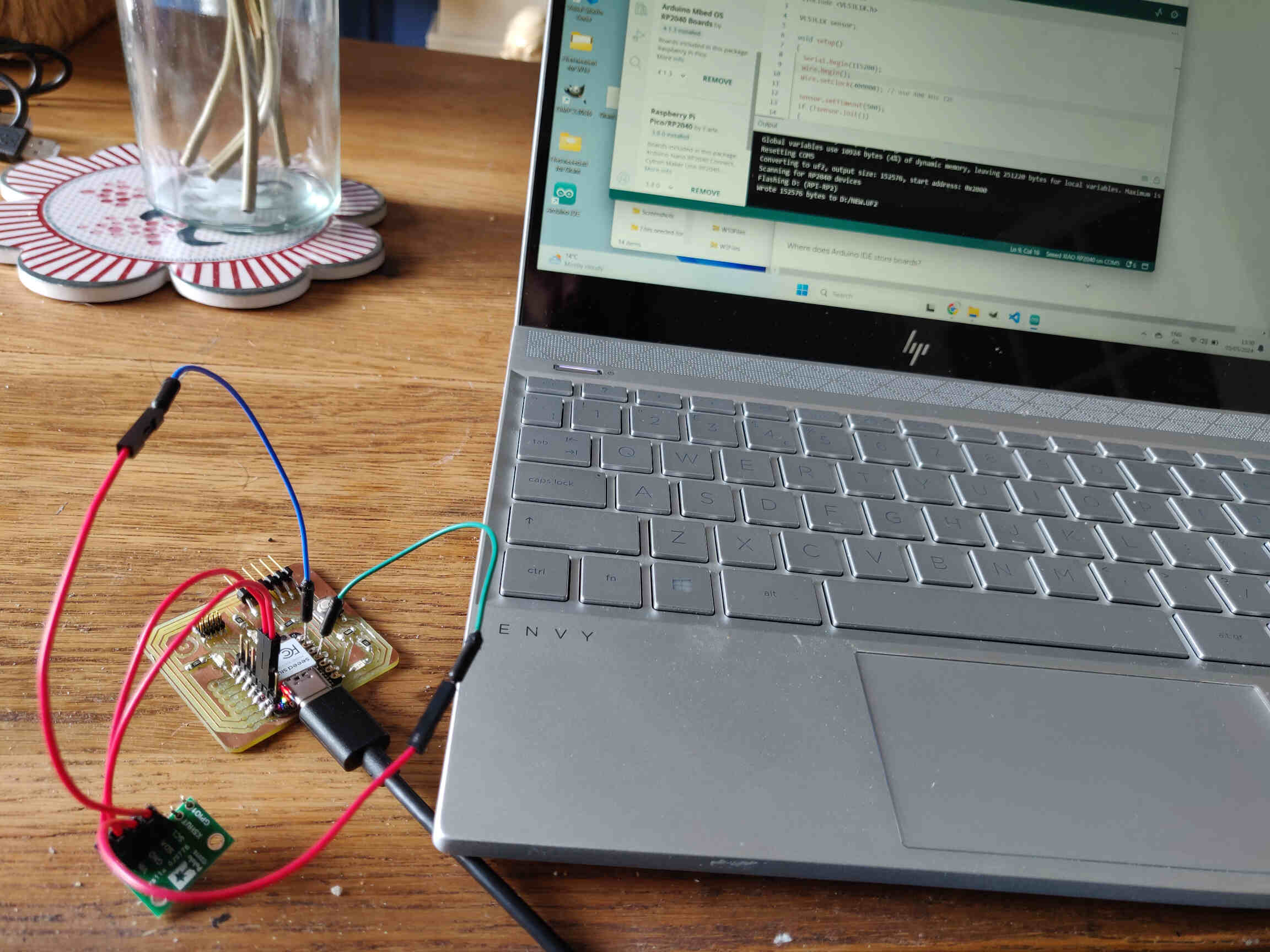
So maybe it was a USB Port issue? Don't know whether to be happy or angry. But I went home to set up my Arduino with each of my computers to see which one works. After trying it out on my desktop computer, the VL53L1X finally worked. I can’t tell you how relieved I was. I immediately tested it using my Quentorres PCB and it worked like a charm! Now the data reads straight from the Serial Monitor.
sensor.setTimeout(500);
if (!sensor.init())
{
Serial.println("Failed to detect and initialize sensor!");
while (1);
}
// Use long distance mode and allow up to 50000 us (50 ms) for a measurement.You can change these settings to adjust the performance of the sensor, but the minimum timing budget is 20 ms for short distance mode and 33 ms for medium and long distance modes. See the VL53L1X datasheet for more information on range and timing limits.
sensor.setDistanceMode(VL53L1X::Long);
sensor.setMeasurementTimingBudget(50000);
// Start continuous readings at a rate of one measurement every 50 ms (the inter-measurement period). This period should be at least as long as the timing budget.
sensor.startContinuous(50);
}
void loop()
{
Serial.print(sensor.read());
if (sensor.timeoutOccurred()) { Serial.print(" TIMEOUT"); }
Serial.println();
}
__________
VIDEO SECTION
Testing Servos
VL53L1X Successes!
VL53L1X w/ Quentorres Successes!
____________
Conclusion / Reflection
Focusing on Motion Sensors as they are highly relevant for my final project. The ‘VL53L1X Time of Flight’ sensor was recommended to me as it's supposedly one of the easiest sensors to get working. Whereas my experience differed highly. After tons of debugging and trying to fix issues that shouldn't have been there, my final thoughts on the VL53L1X is that it's highly unreliable.
I seemed to have had everything done correctly. The wire connections were correct, the code was correct, the wires had been replaced, tried at different voltages and pins, tried with different & stronger USB ports, etc etc, - And yet, the sensor would very rarely work for me. Even when I finally got it working on my computer, it stopped working when I returned to it a week later - with everything still as it should be, and yet it consistently “Failed to Detect Sensor”. Myself, my local instructors and Global Open Time instructors couldn't find the issue. We only had access to 2x Time of Flight sensors in our FabLab and the 2 I had seemed faulty or defective.
Although I considered the VL53L1X to be the exact sensor I needed for my final project, I ultimately made the decision to change sensors for my final project due to how unreliable the Time of Flight sensor was.
Possible alternatives are light sensors or a Step response sensor. But later on during a Global Open Time, the “Hall Effect” sensor was recommended to me as it is one of the easiest sensors to get working and doesn't even need a library for the code to work.
Although I have already made so many concessions towards my final project, I know the most important thing for my presentation is to “make something that WORKS”.
Final Thoughts: Everytime I think I have “figured out” Electronics and Programming issues, there's always another wrench in the way that affects the design of my project. I wanted to be better and grow using electronics in my projects, but now I'm all but certain that I'll never touch electronics after I'm finished with Fab Academy. I wish things could have been different but they aren't. Dear Electronics / Programming… it's not me, it's you.