Group Assignment:
Group Assignment Link:
____________
Servo Motor Power Consumption Results:
Note: (Readings may vary due to Faulty Lab / Testing / PCB Tools & Equipment)Voltage (V) x Amps (A) = Watts (W)
For a more information regarding Multimeters and Oscilloscopes please visit the Group Assignment on Week 8 - Electronics Design.
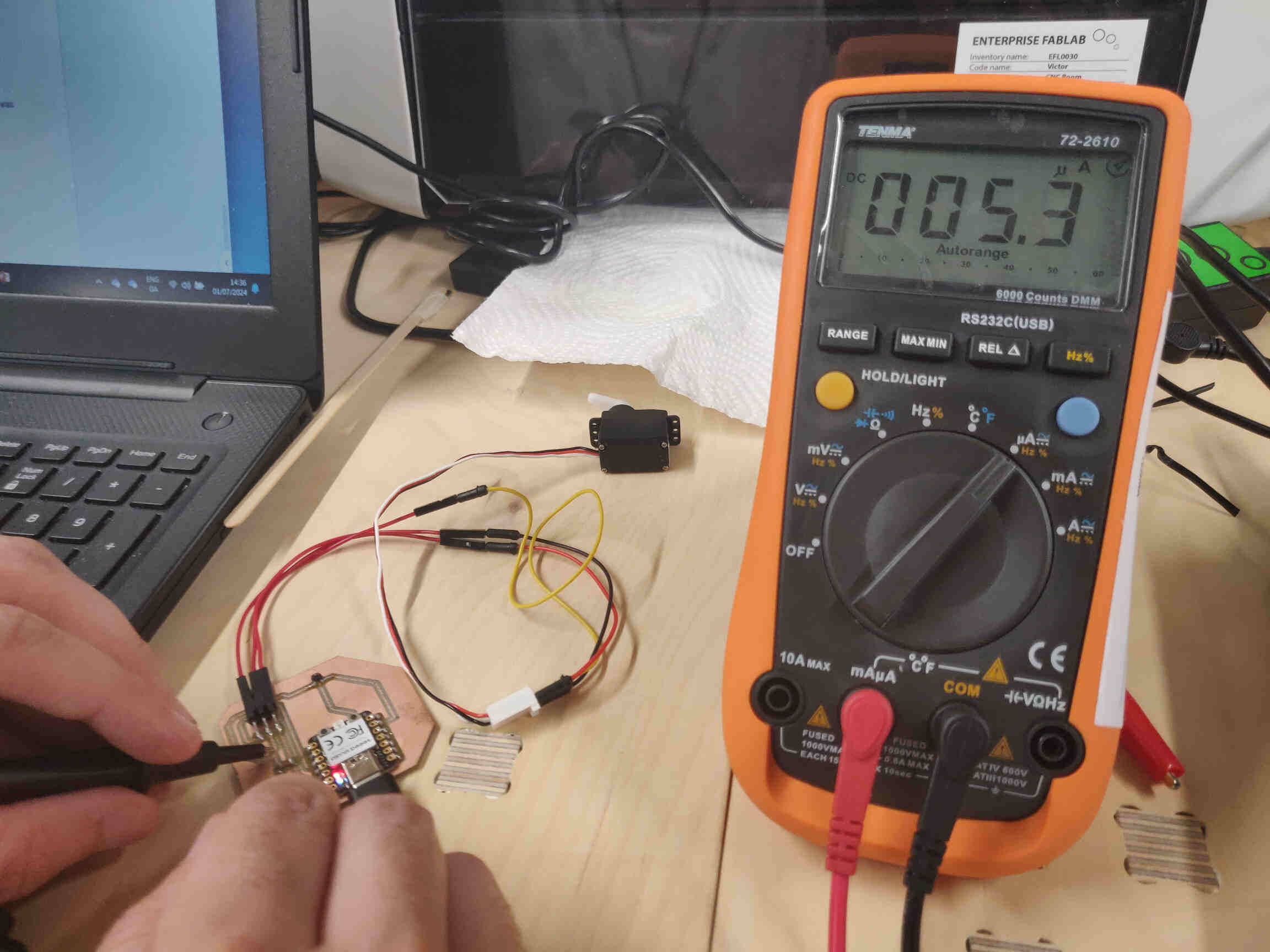
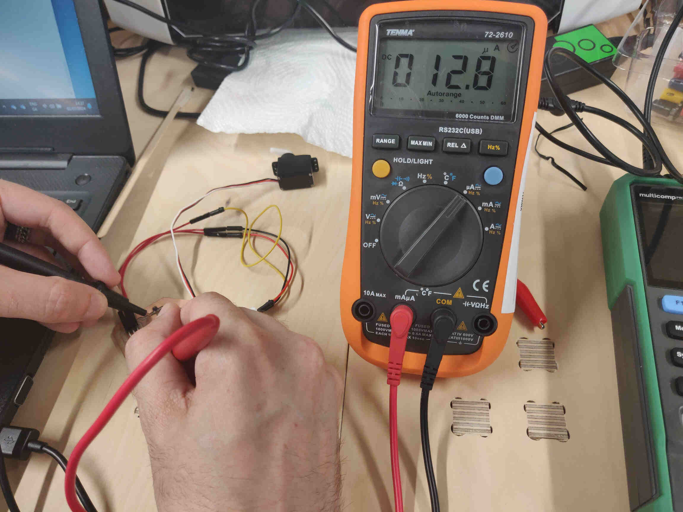
Multimeter: Servo Connection while inactive: 4.6 (V) - 5.6 (A)
Multimeter: Servo Connection while active: 1.8 (V) - 5.7(A)
*(V) = Voltage
*(A) = Amps
How to Measure Watts with a Multimeter Tenma 72-2610 Multimeter Manual
____________
Individual Assignment:
____________
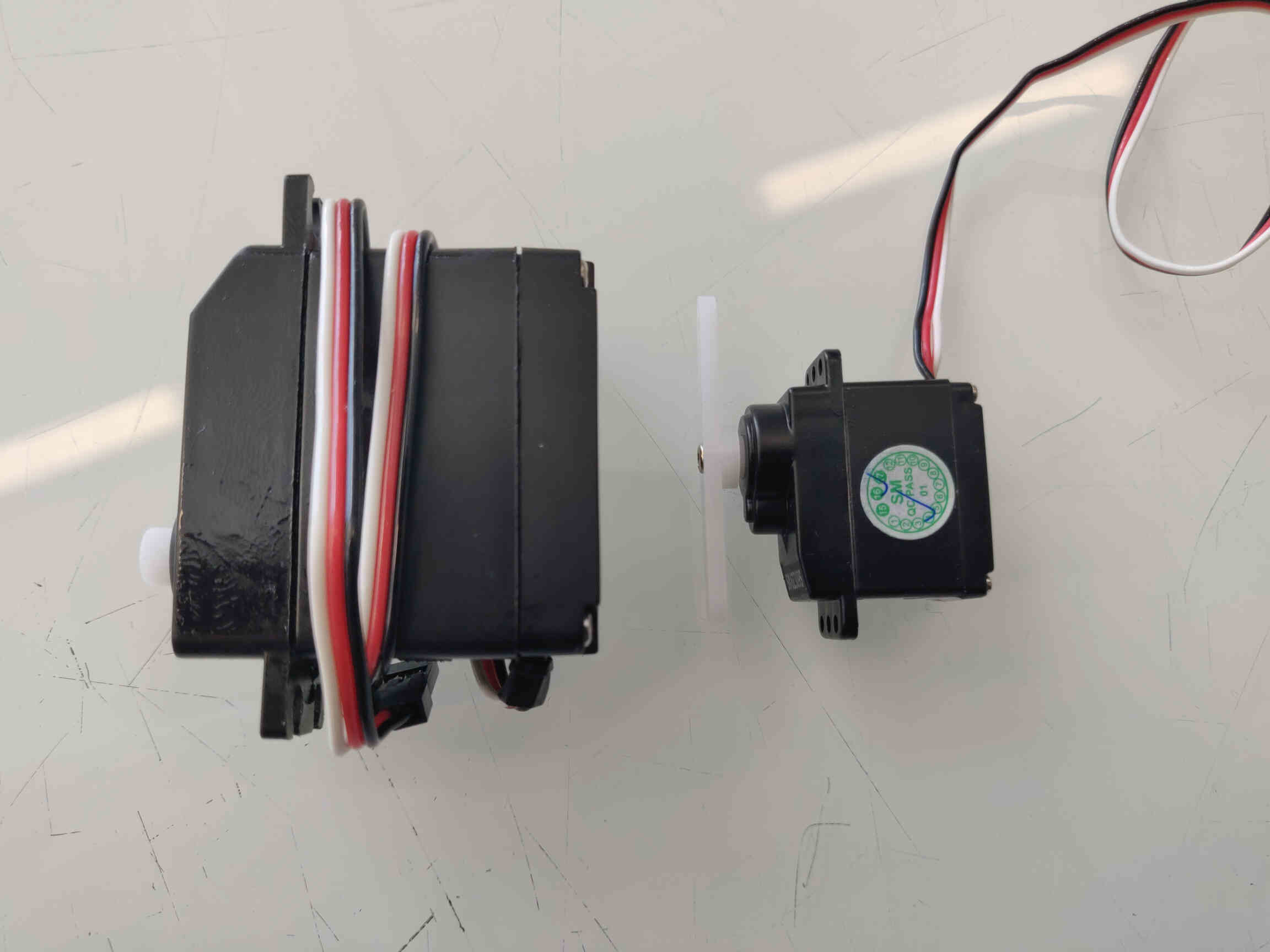
Research into Servo Motors
This week we’ll be focusing on motion outputs such as Servo and Stepper motors - however it is my full intention on using a Servo Motor for my Final Project so I will spend most of the assignment focusing on those.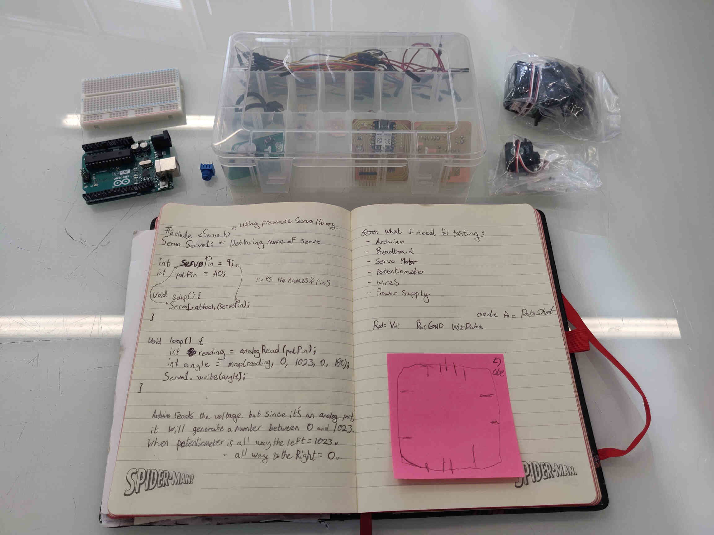
Servo Motors - 50Hz - 1.2ms - They run on the supply voltage - typically 5 volts.
Also take note of Stepper Motors. There’s such a thing as ‘Silent Stepper Motors’. But you can implement silent steppers into regular steppers using ‘microsteppers’. Change the drivers to adjust the noise.
References used in my initial Research:
- Servos explained- Arduino Servo Basics
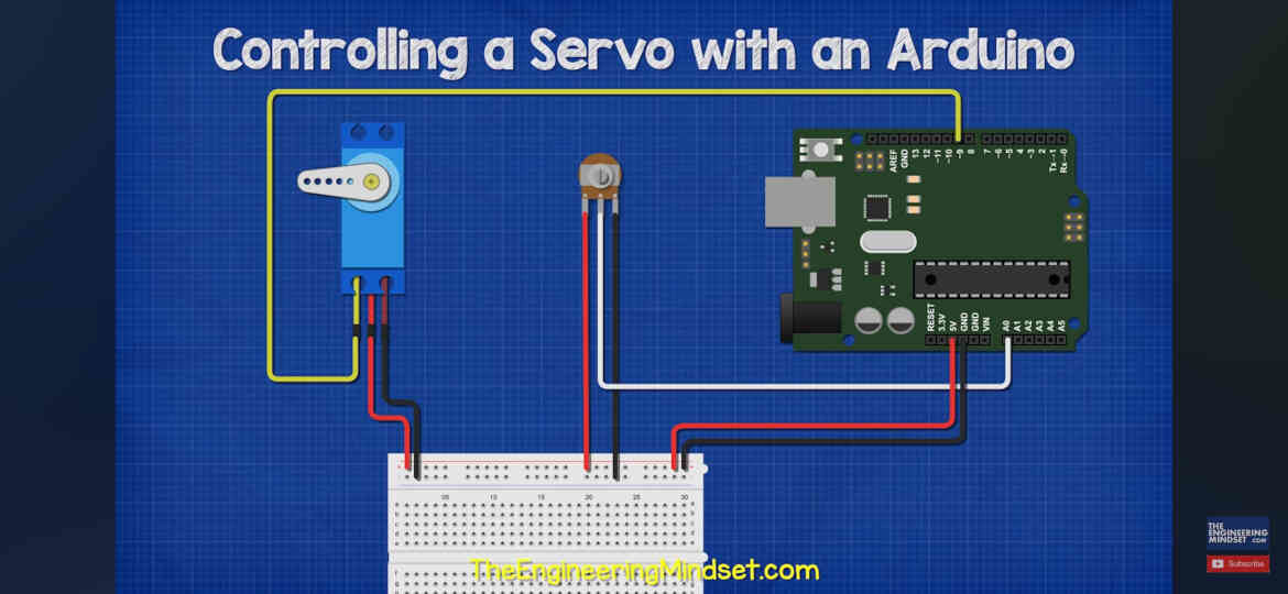
- How to Control a Servo With an Arduino
- Servo Motors, how do they work?
- Quick Guide to Servos
- Output Assignment Example
- How to program PCB using Quentorres
- UPDI Connection
— — —
Goals:
What I need for testing:
Potentiometer Wires:
Red = (V)oltage / Black = GND / White = Data
— — —
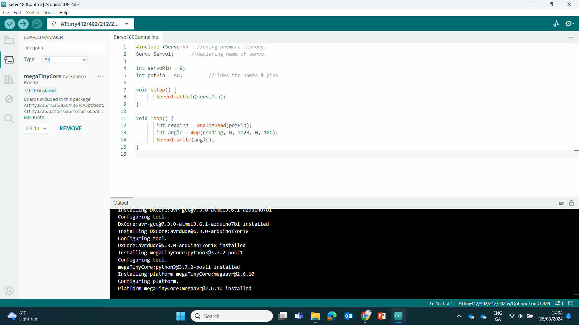
Code for Analog Motor:
Servo Servo1; //declaring name of servo.
int servoPin = 9;
int potPin = A0; //links the names & pins
void setup() {
Servo1.attach(servoPin);
}
void loop() {
int reading = analog read(potPin);
int angle = map(reading, 0, 1023, 0, 180);
Servo1.write(angle);
When the potentiometer is all the way to the left, it will reading 1023volts.
When the potentiometer is all the way to the right, it will reading 0volts
— — —
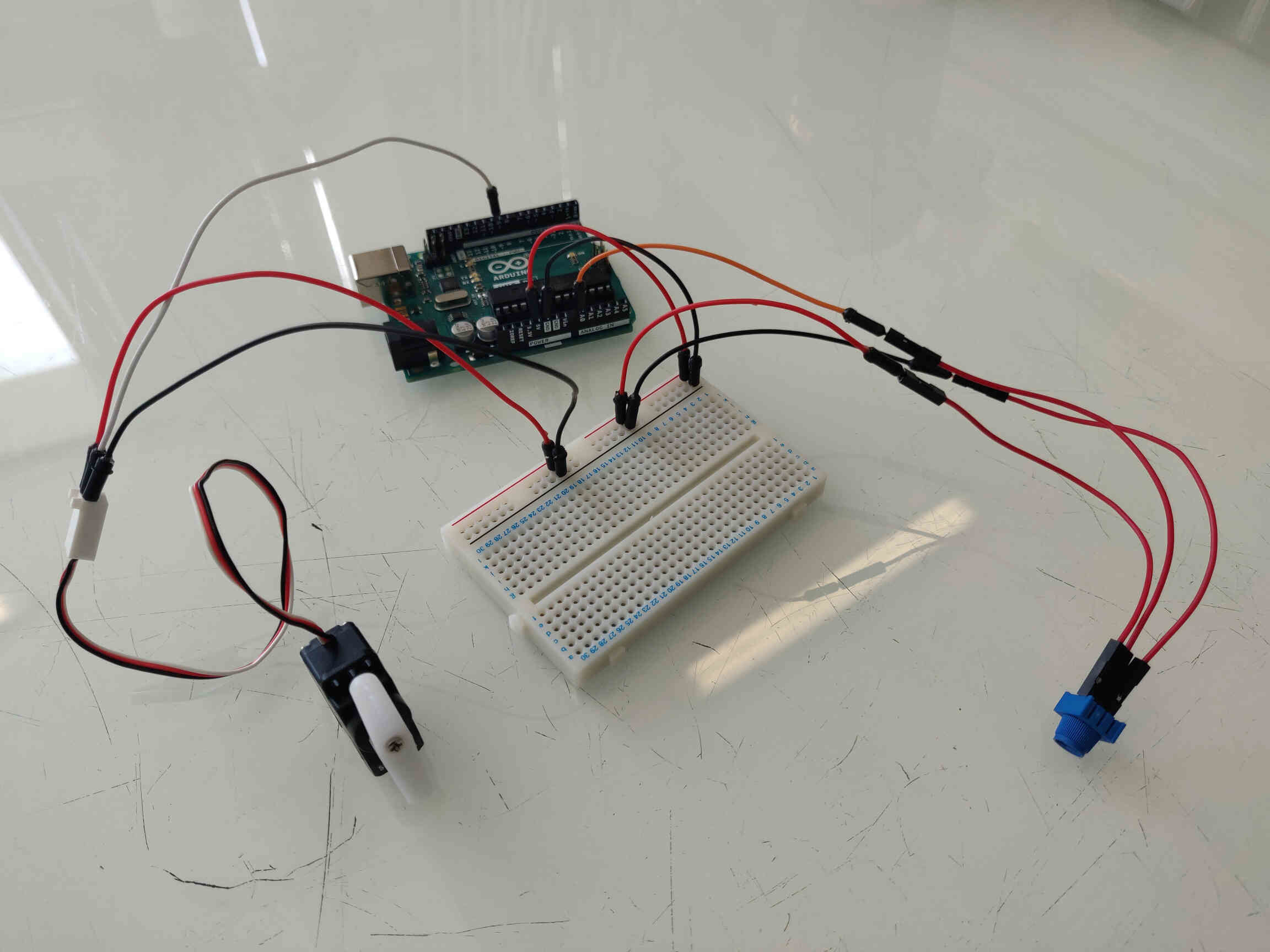
Wire Connections:

*Rail = on Breadboard
*Port = on Arduino
Note: After an in-depth look at the code and wiring for my Potentiometer, Oscar reminded me that since the Potentiometer is an Input, it doesn’t actually relate to this week’s assignment. He also described the process for this assignment - which I was confused about originally.
— — —
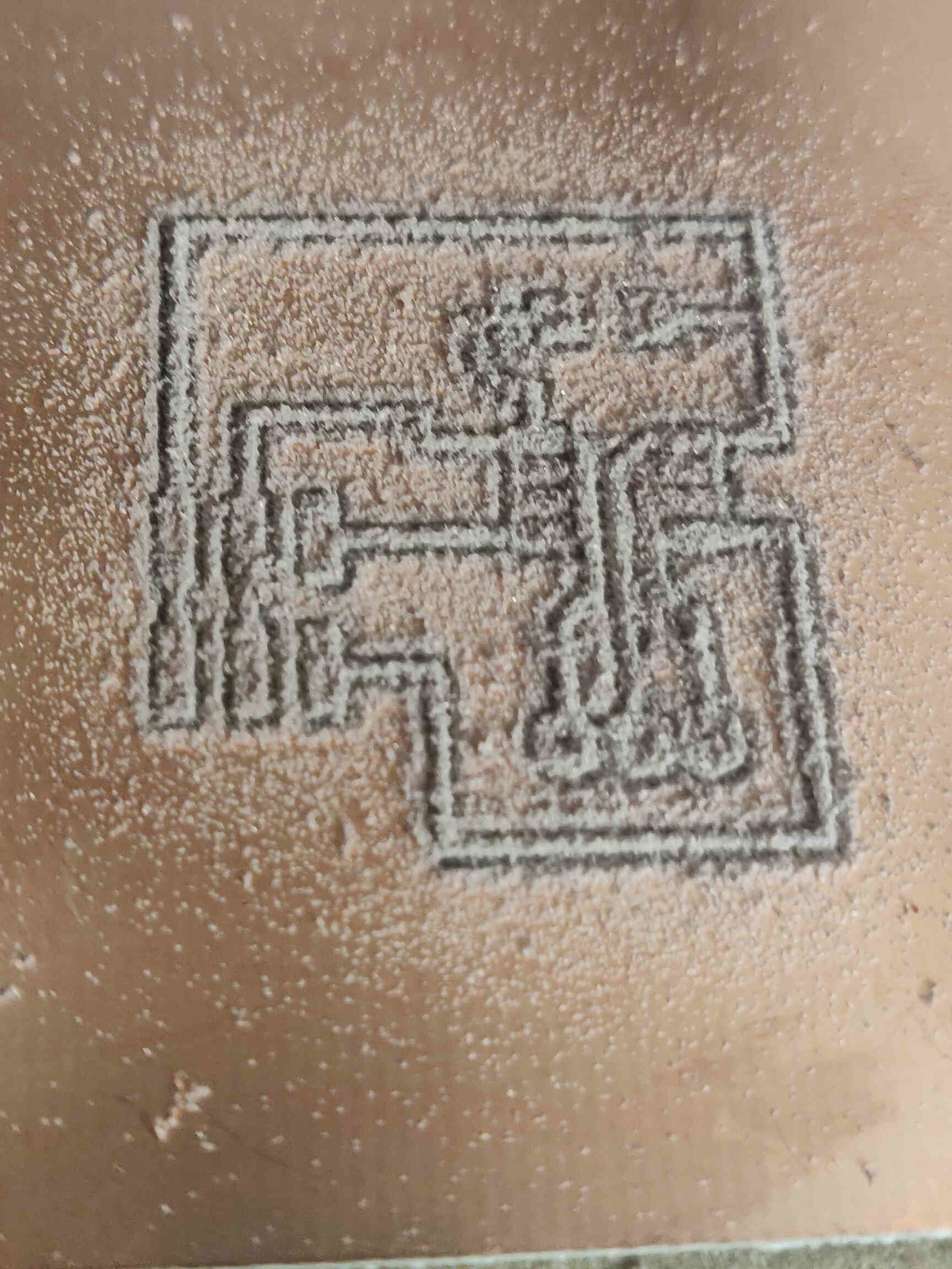
Designing a Hello.Servo Board
PCB Designing using KiCAD
Updated Process: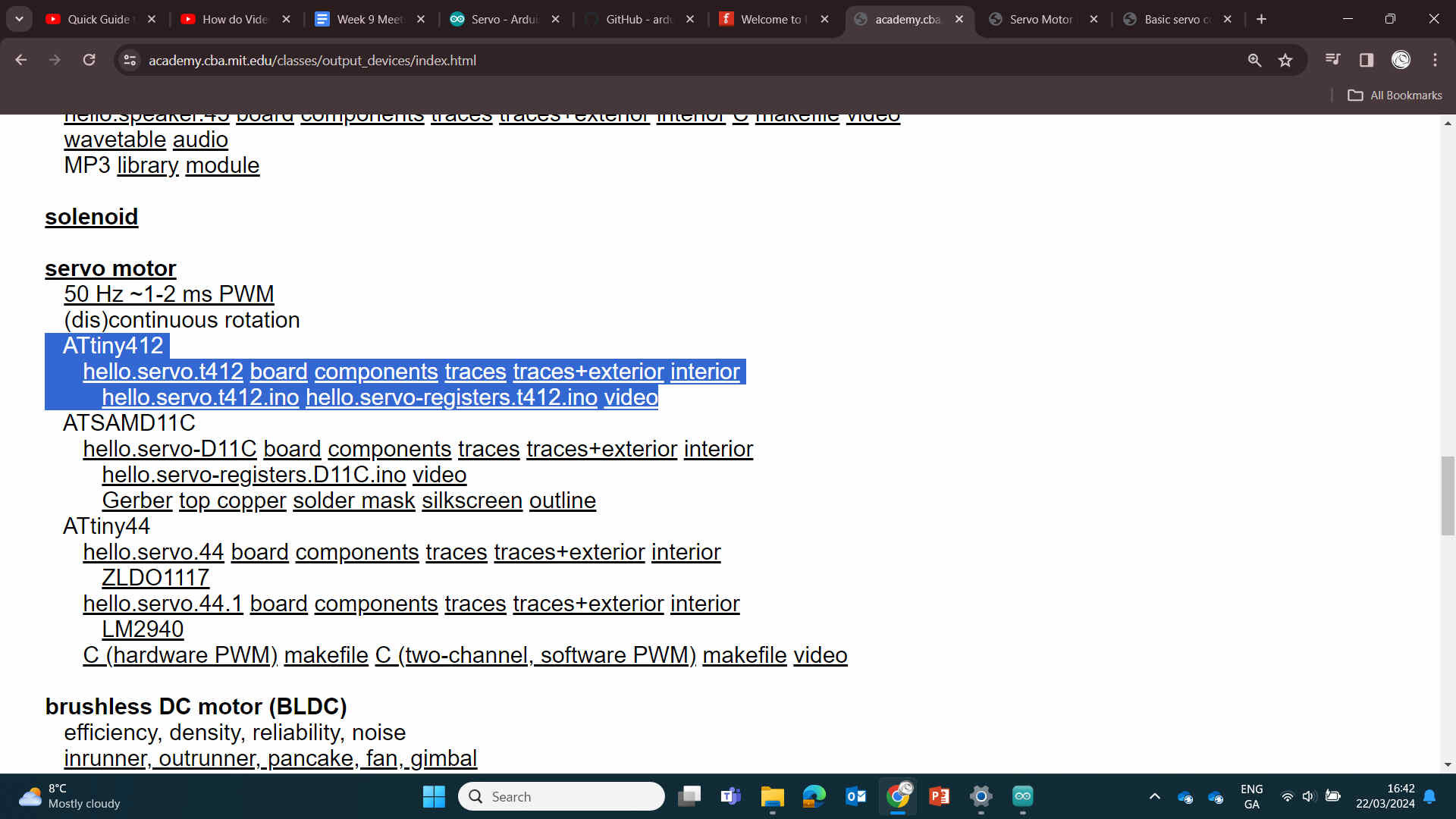
Followed this PCB design: ‘Hello.servot412’
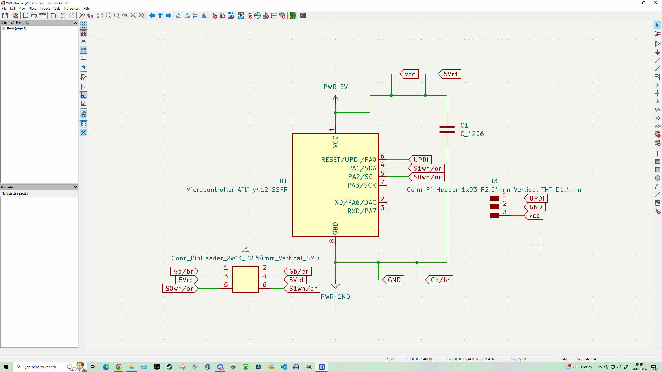
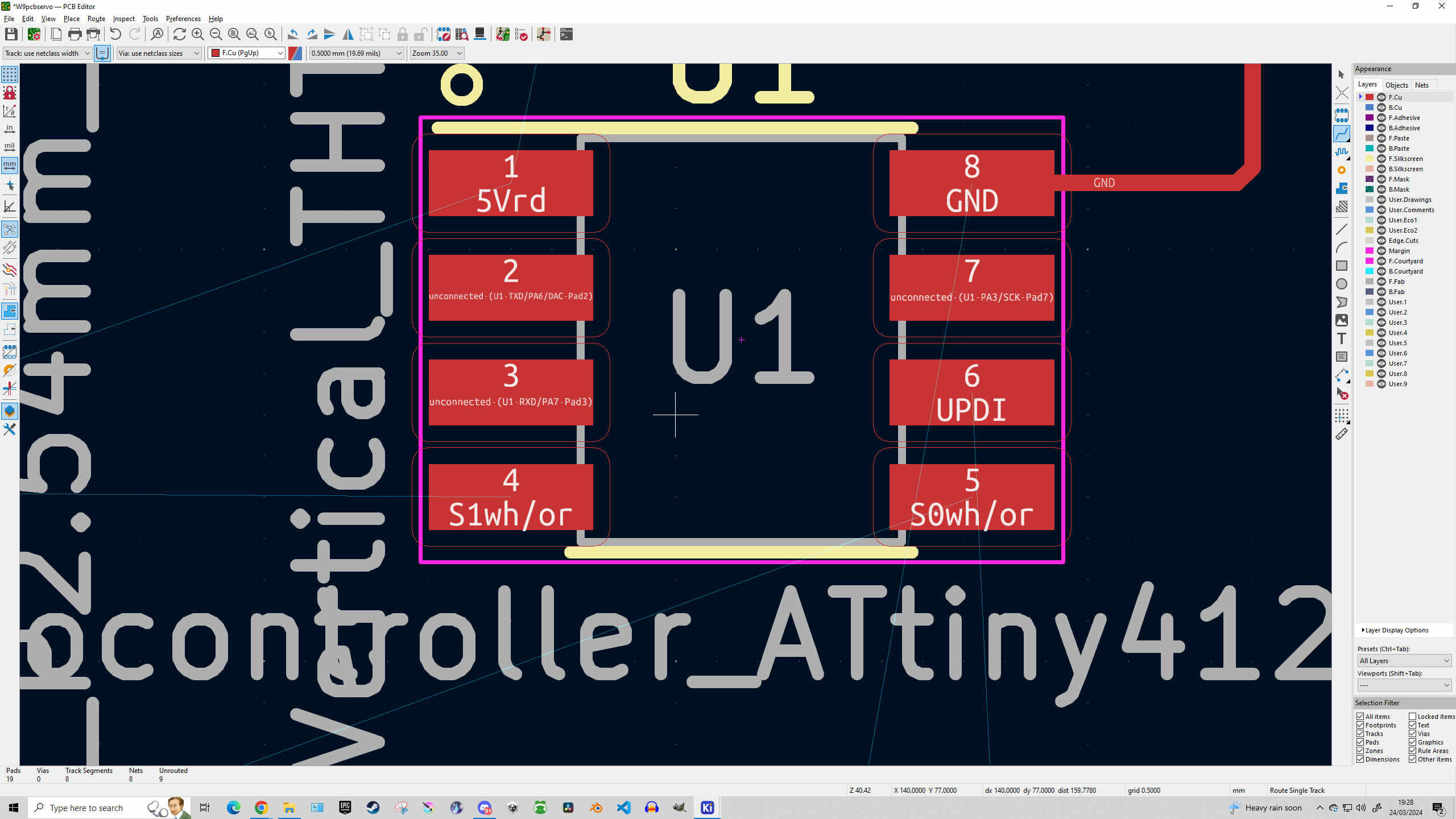
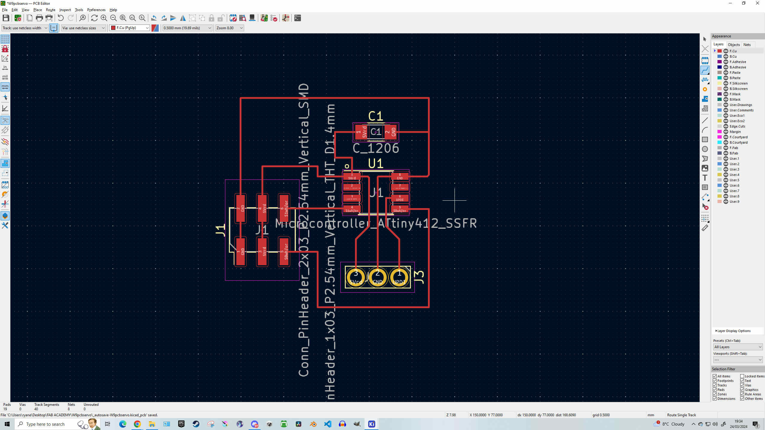

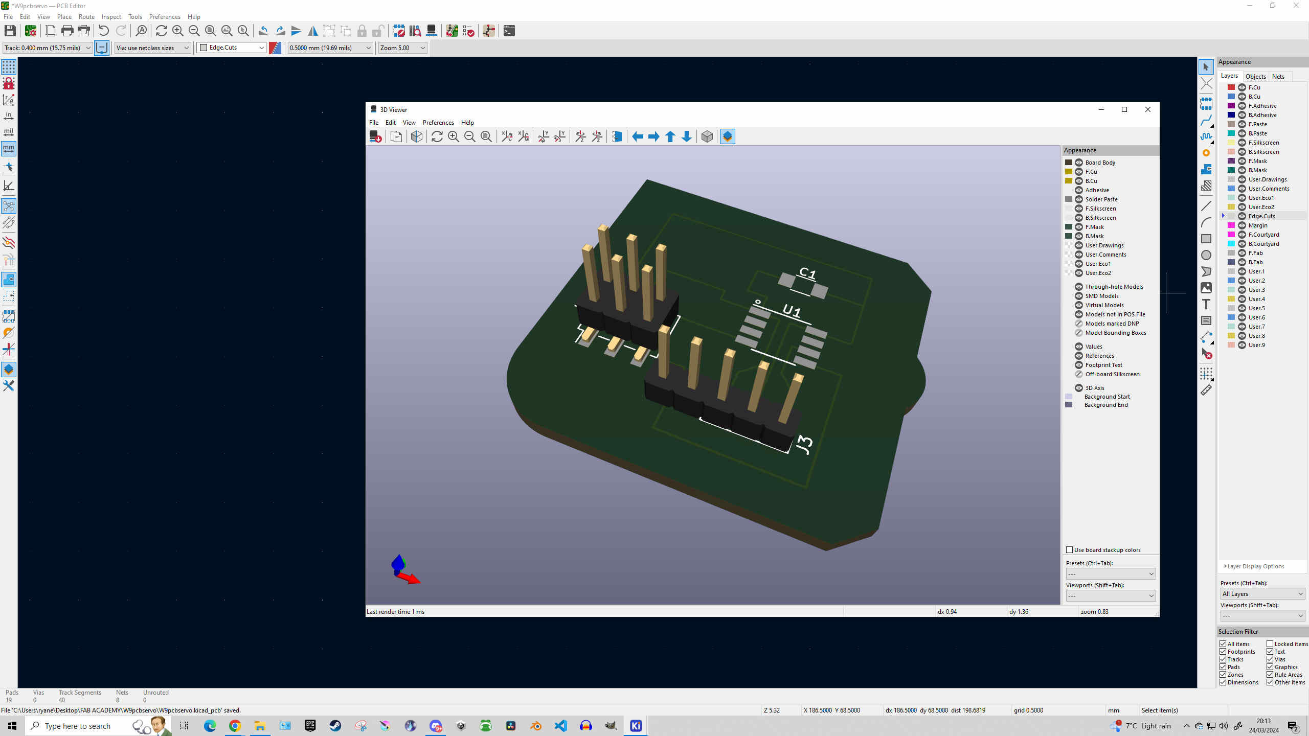
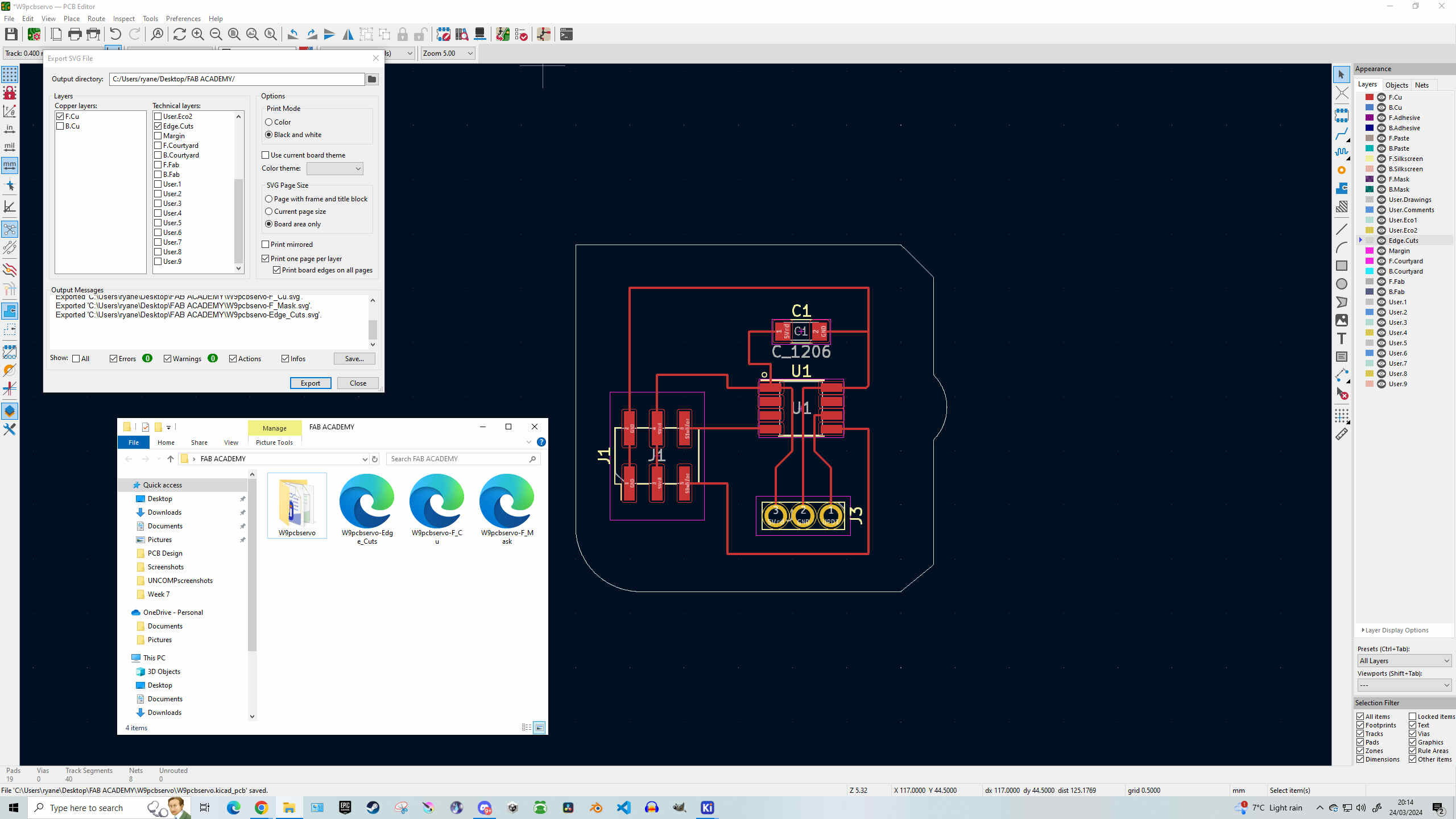
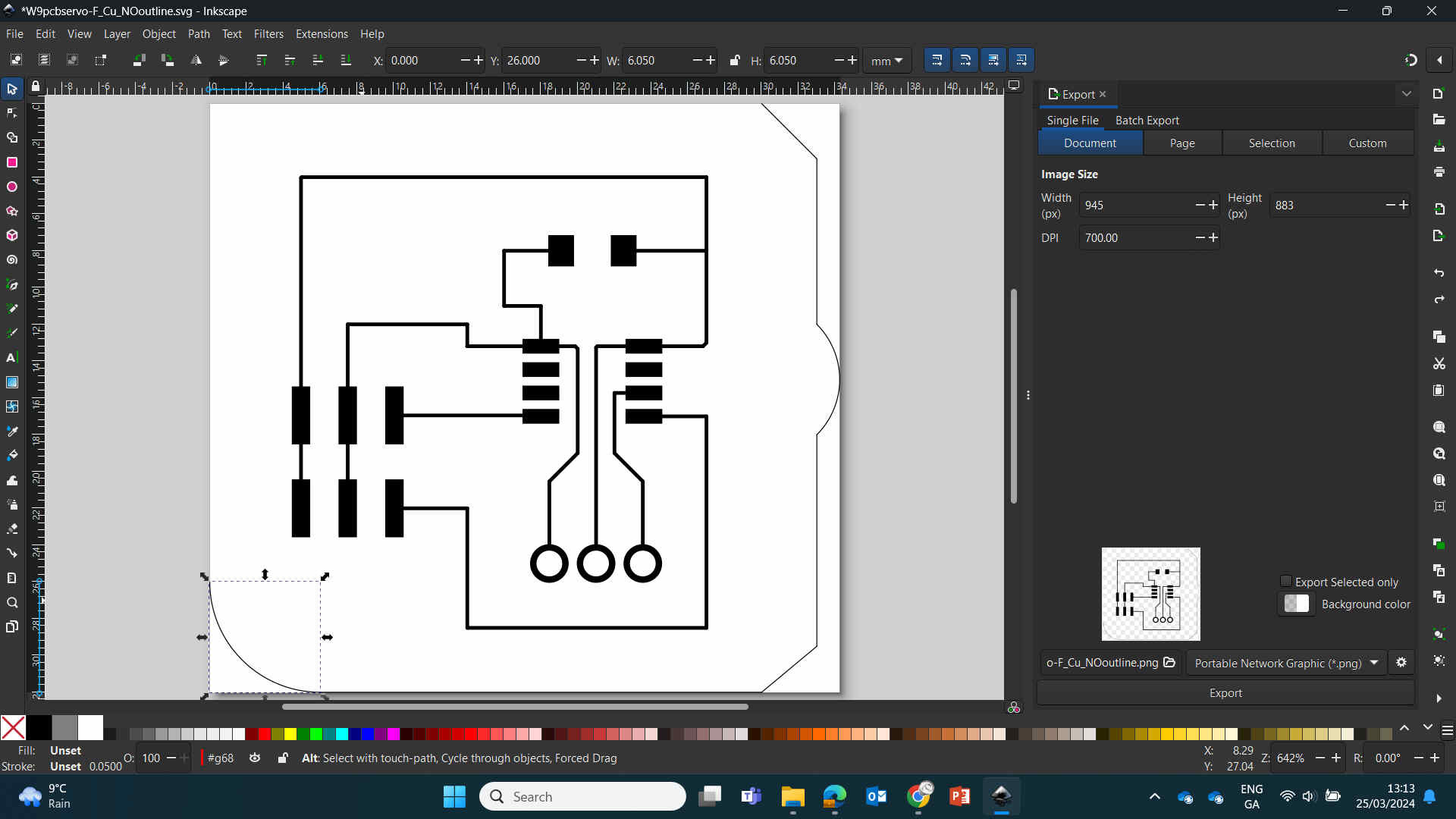
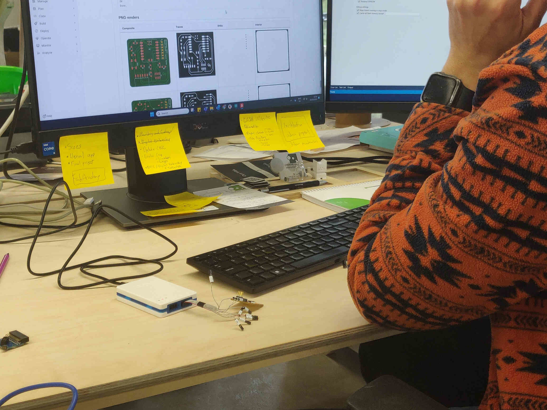
Using KiCAD to complete my design, I was getting confused about what changes I needed to make to fit the servo and still run perfectly, but I went back and forth between my first PCB made in Week 8, my new design, the hello.servo412 PNG and broke it down to which traces lead to what components and why. Eventually I completed my design in KiCAD, used the Design Checker to make sure there are no issues, took a glance at my PCB in the 3D Viewer, then exported it as an SVG to be brought into modsproject.org.
`
— — —
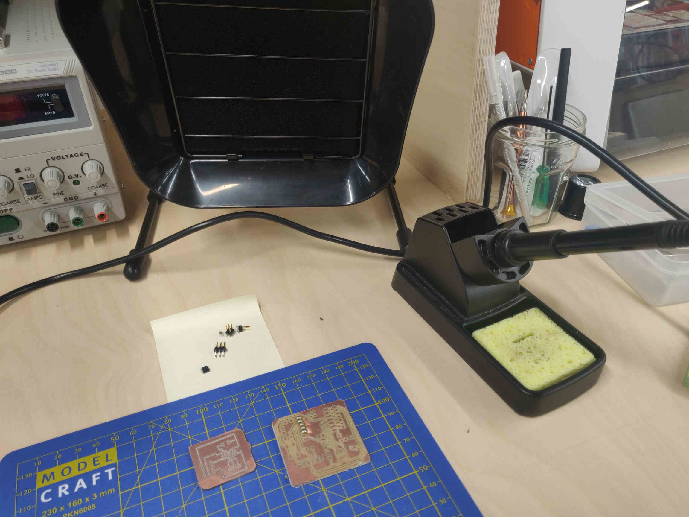
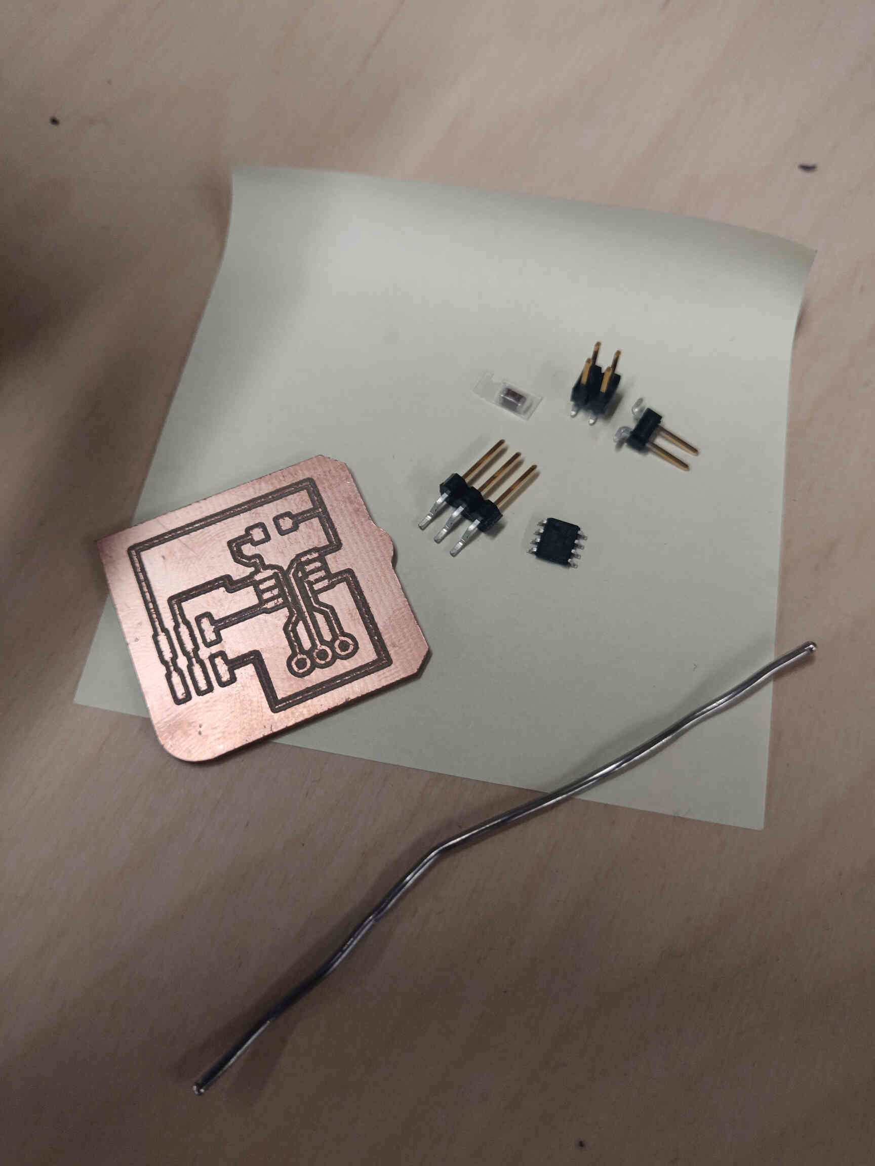
Milling and Soldering
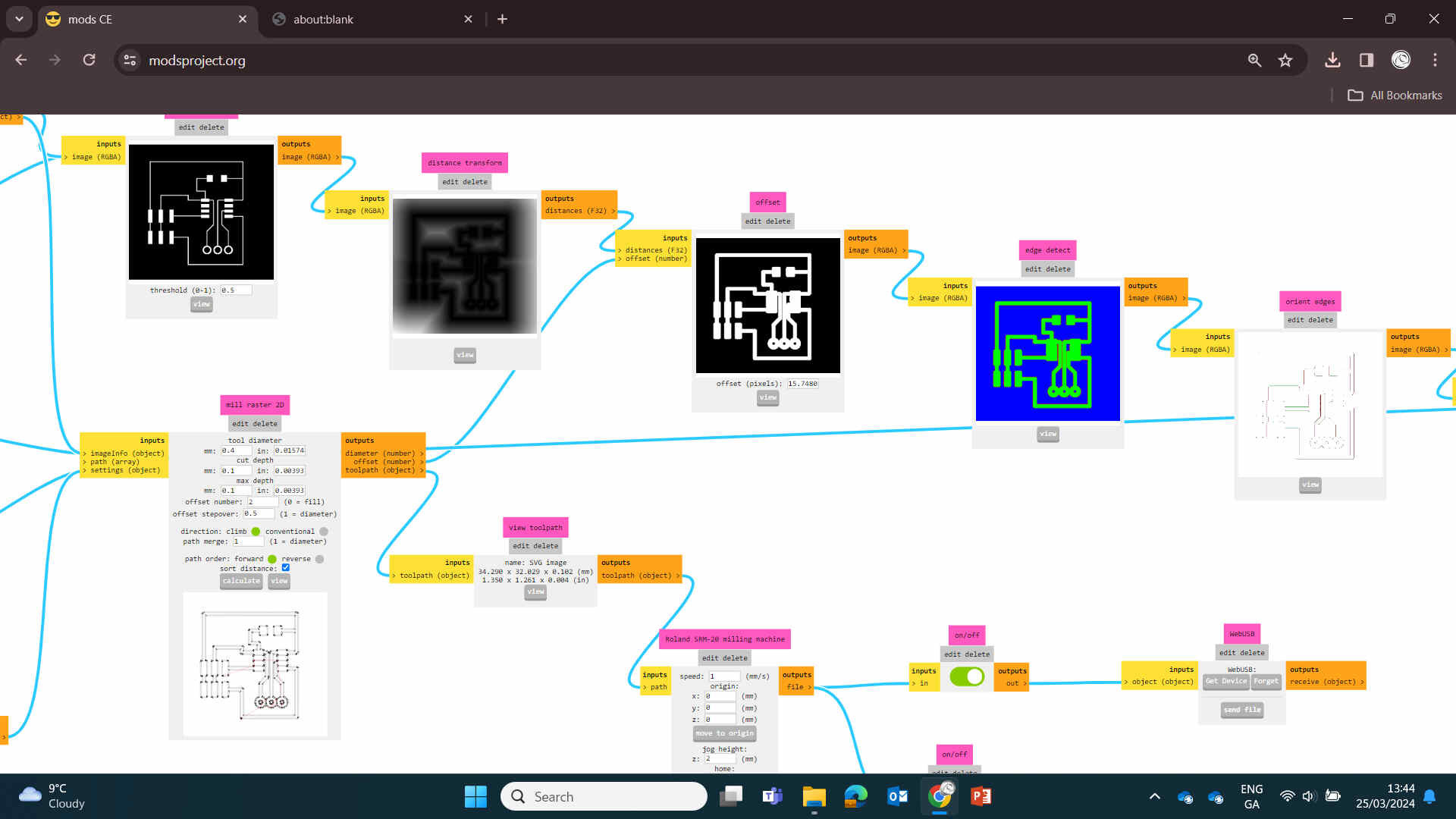
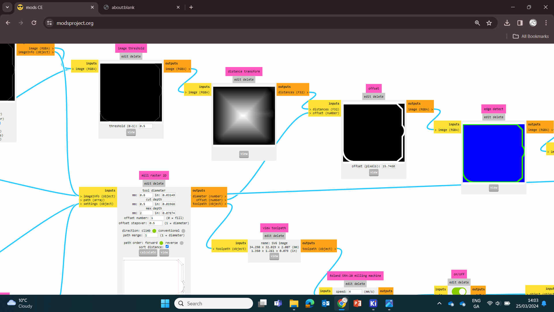
Traces use the 1/64 End Mill at 0.4mm, Outline uses 1/32 End Mill at 0.8mm.Further detail about Modsproject settings can be found in Week 4 Documentation.
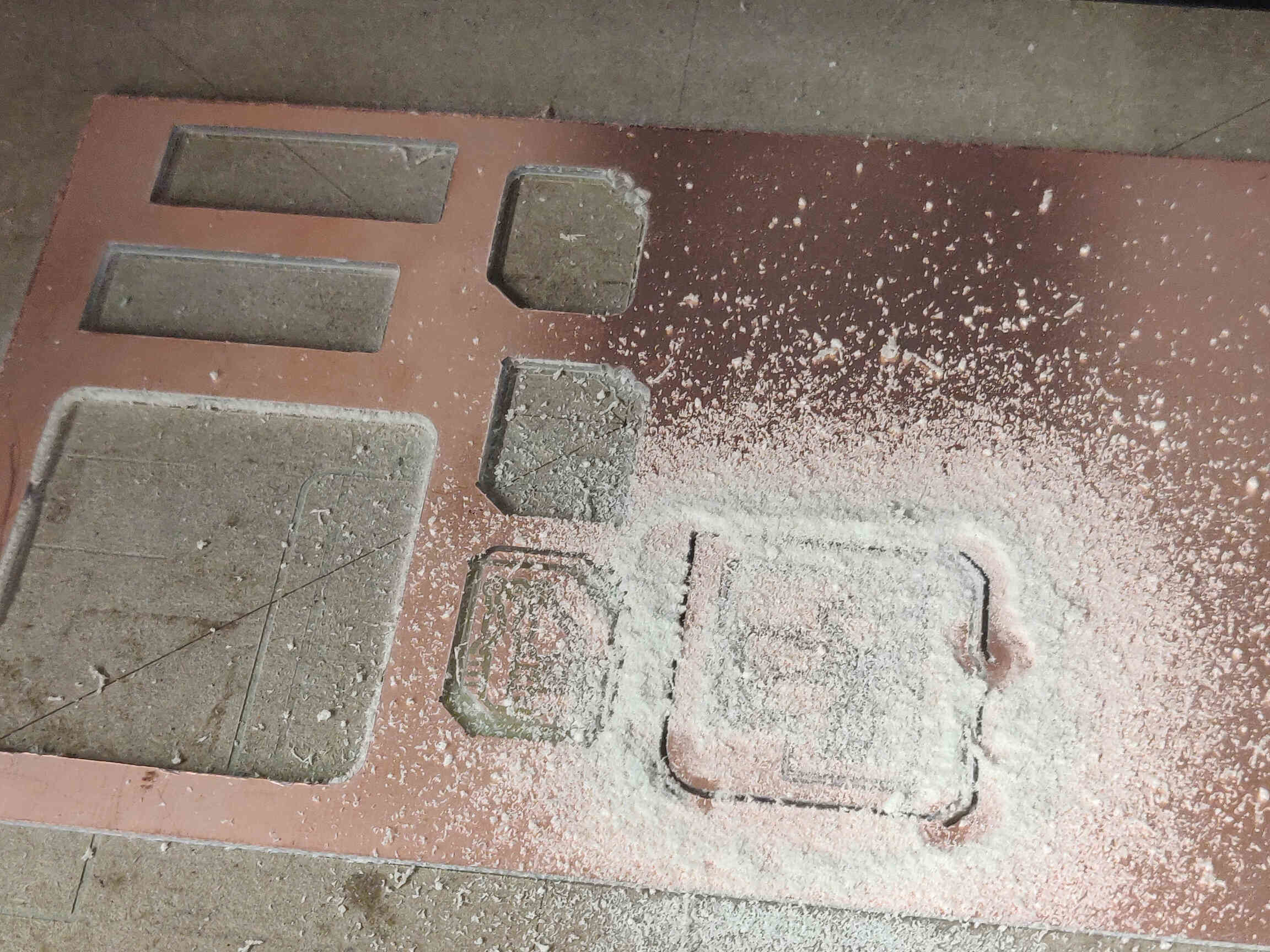
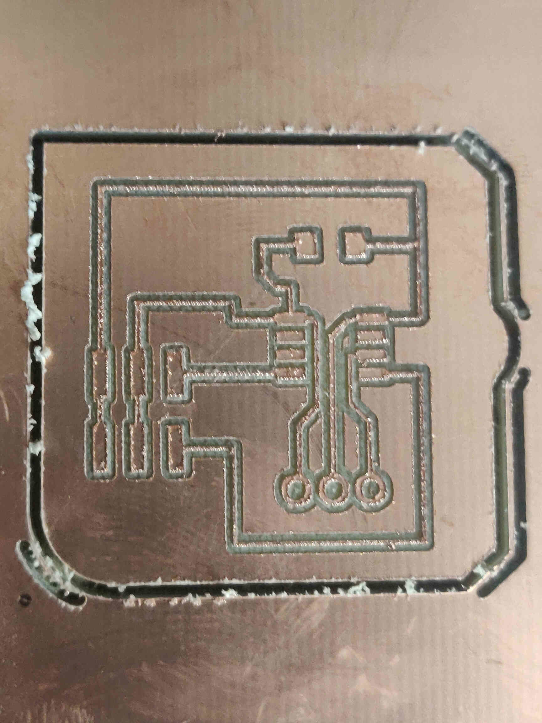
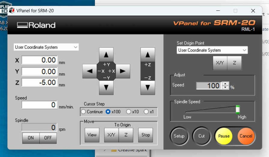
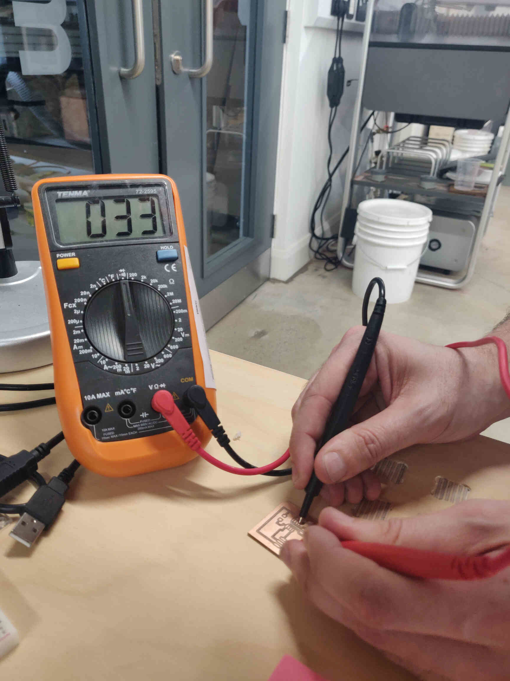
Milled the AtTiny board, Soldered it and used the multimeter to check its connections. Everything was fine but the traces were super thin which was a concern, but thankfully the connections were still going strong. With the board design & production complete, I now need to 'activate' it.
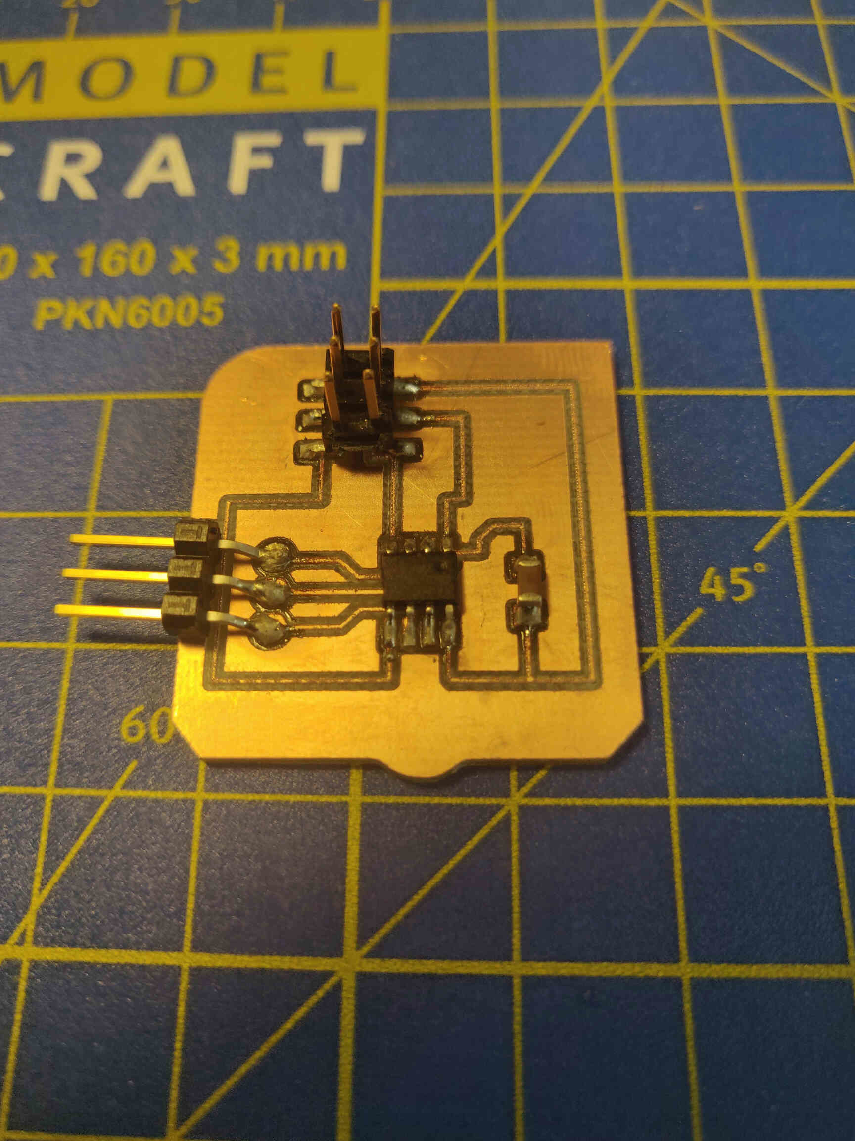
Next we had to use a programmer to activate the AtTiny microcomputer. To do this, I planned on having either an Arduino Uno or my Quentorres activate the AtTiny board. Having the servo motor work was extremely important towards my final project as I would need 3 servos working in tandem to move the arms and head of my product when it senses human interaction. (This would later be changed to just 1 servo controlling the neck).

— — —
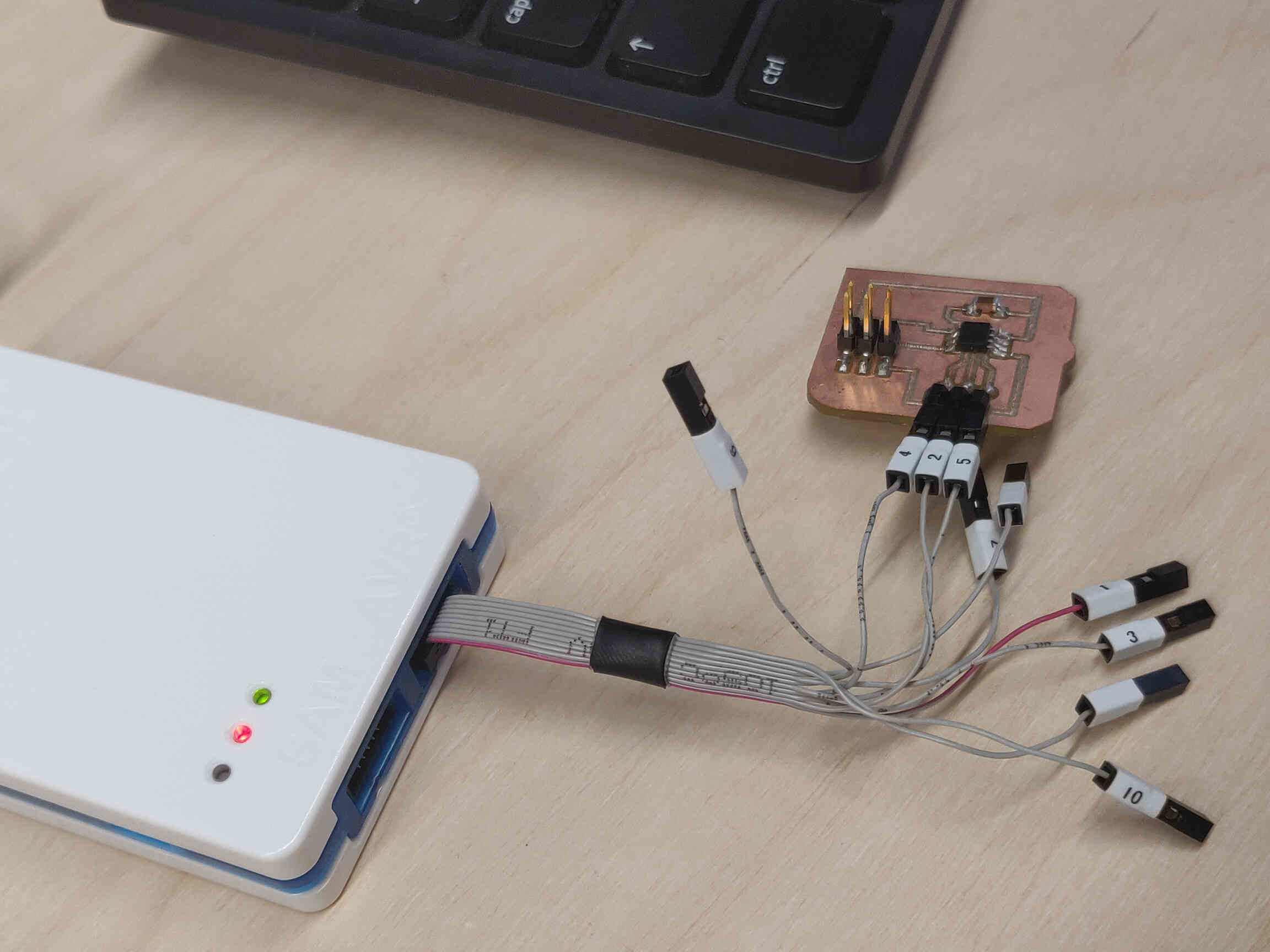
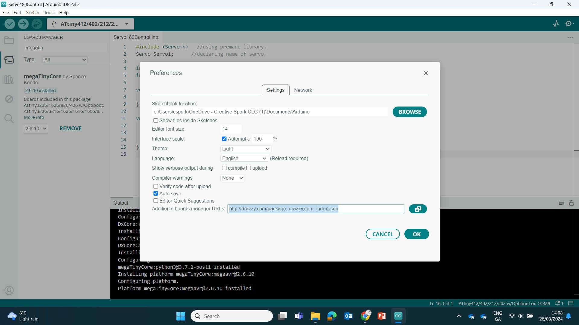
Programming
Bootloader Troubleshooting & Xiao Update
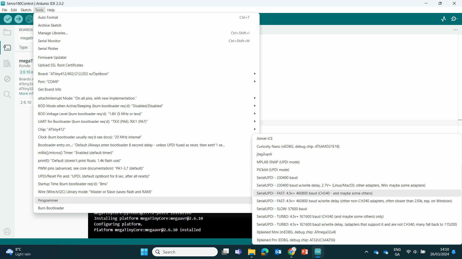
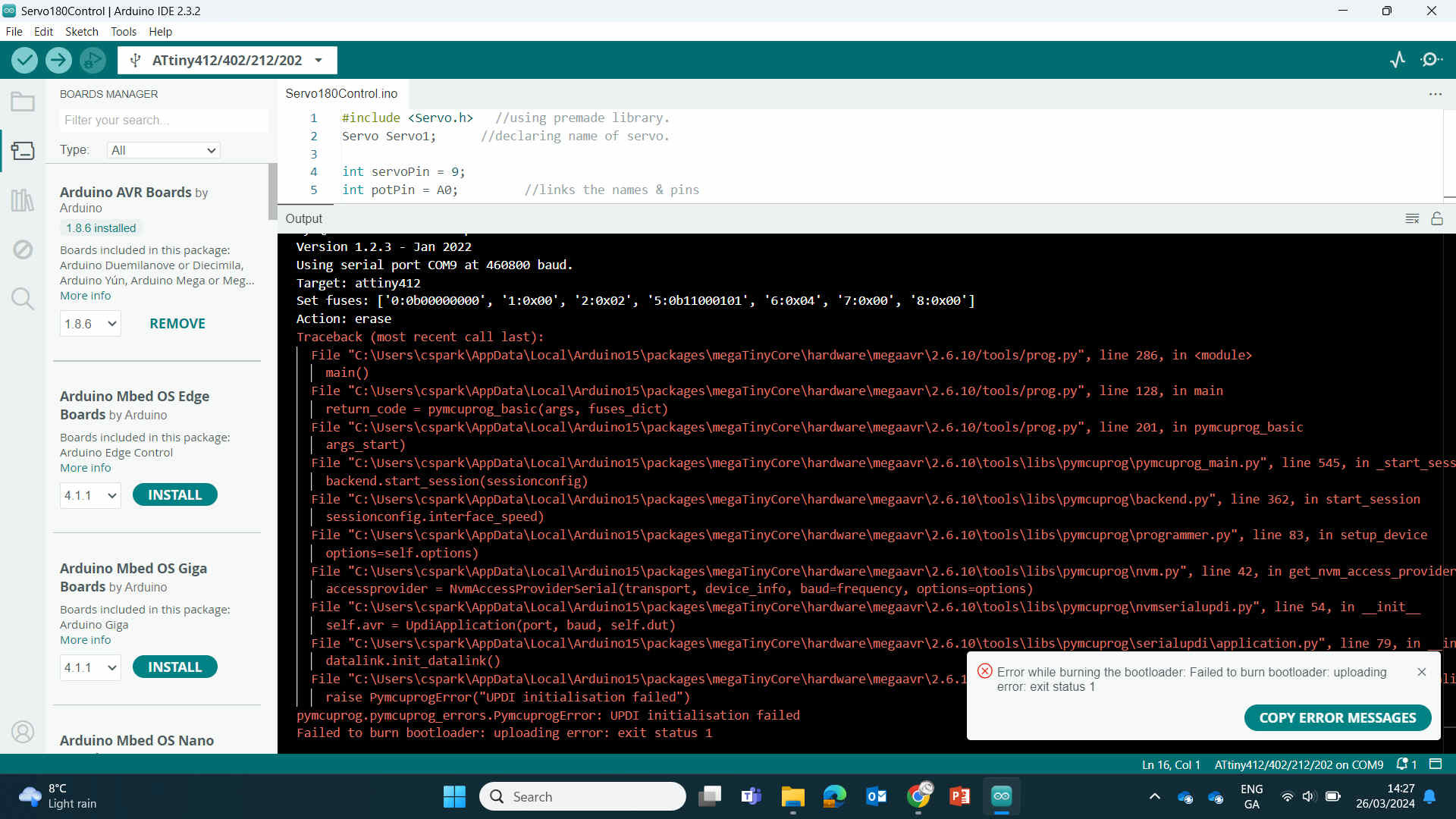
EDITOR’S NOTE: This is where I failed to activate the board using several different techniques. Tried activating using the Quentorres and the Ardunio Uno and failed both times due to various reasons (unable to find ‘Burn Bootloader’ due to having the wrong board selected - later learned that the board I was trying to activate needed to be the board selected - not the programmer). Then there were issues finding the correct wiring, etc. We decided to resort to using an actual programmer to activate the board but failed to get the correct software downloaded, wiring, compatibility, etc.
I was working closely with my instructor Oscar during this and we both had major trouble finding the issue after days of trying. After days of failure and wasted time, we contacted Nulea for advice and hoped we may get 1 on 1 time to fix this problem as it is the same issue that stopped me from completing other weekly assignments and it has just snowballed at this stage. In the end, after getting advice from Nulea and looking at how other students completed this task - we noticed we can just use the Quentorres board to connect to the servo motor. So we went from there.
— — —
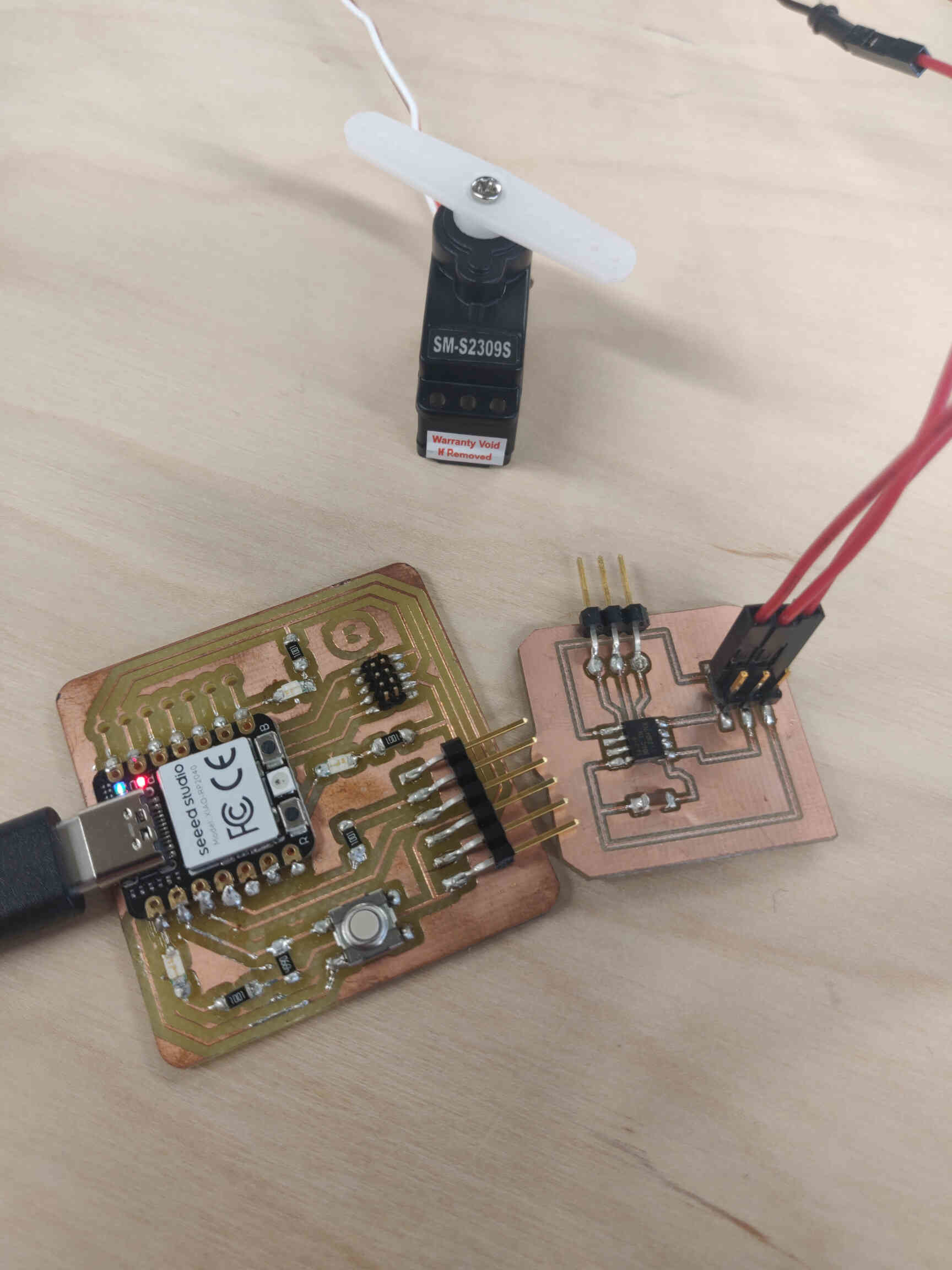
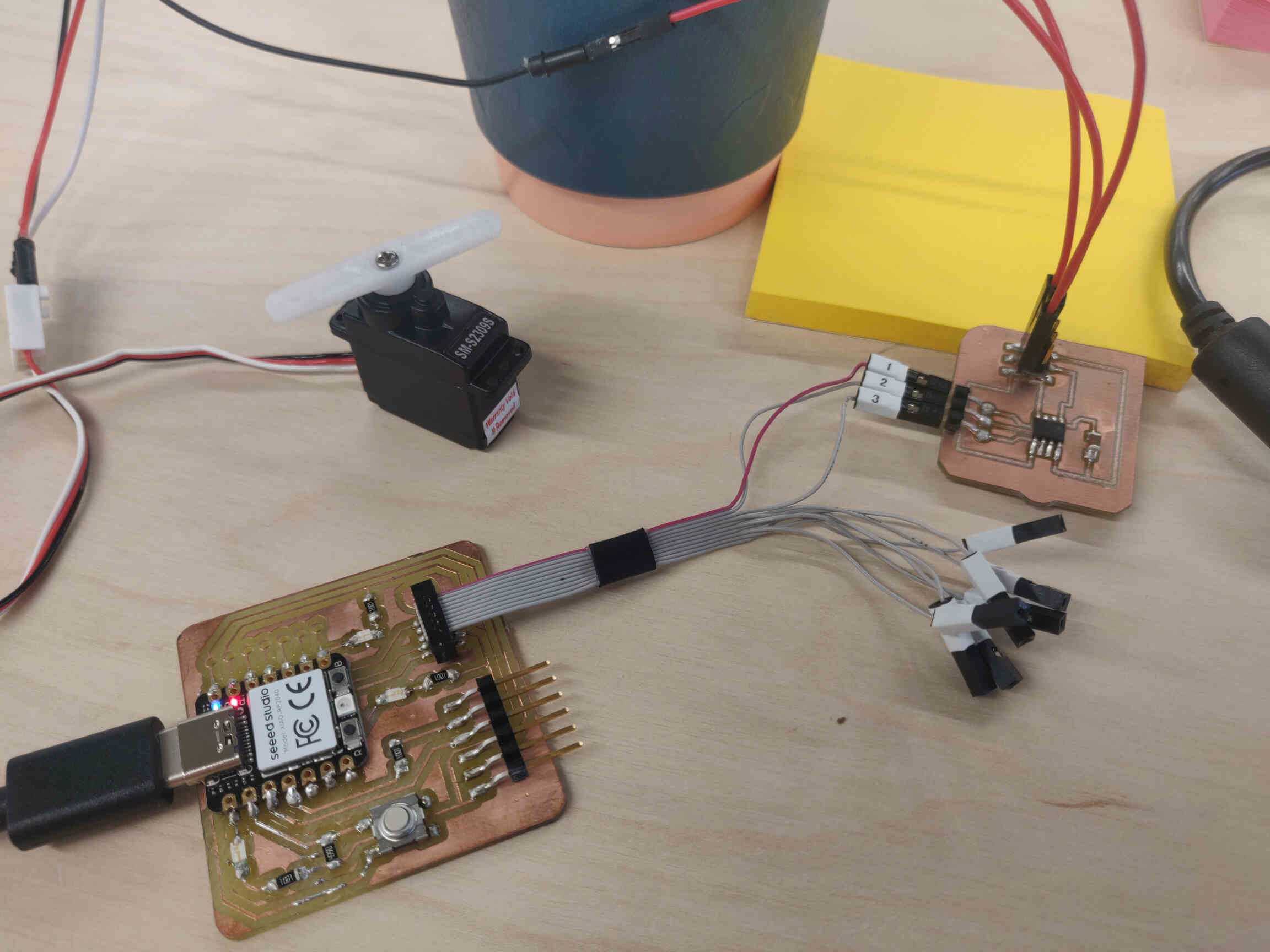
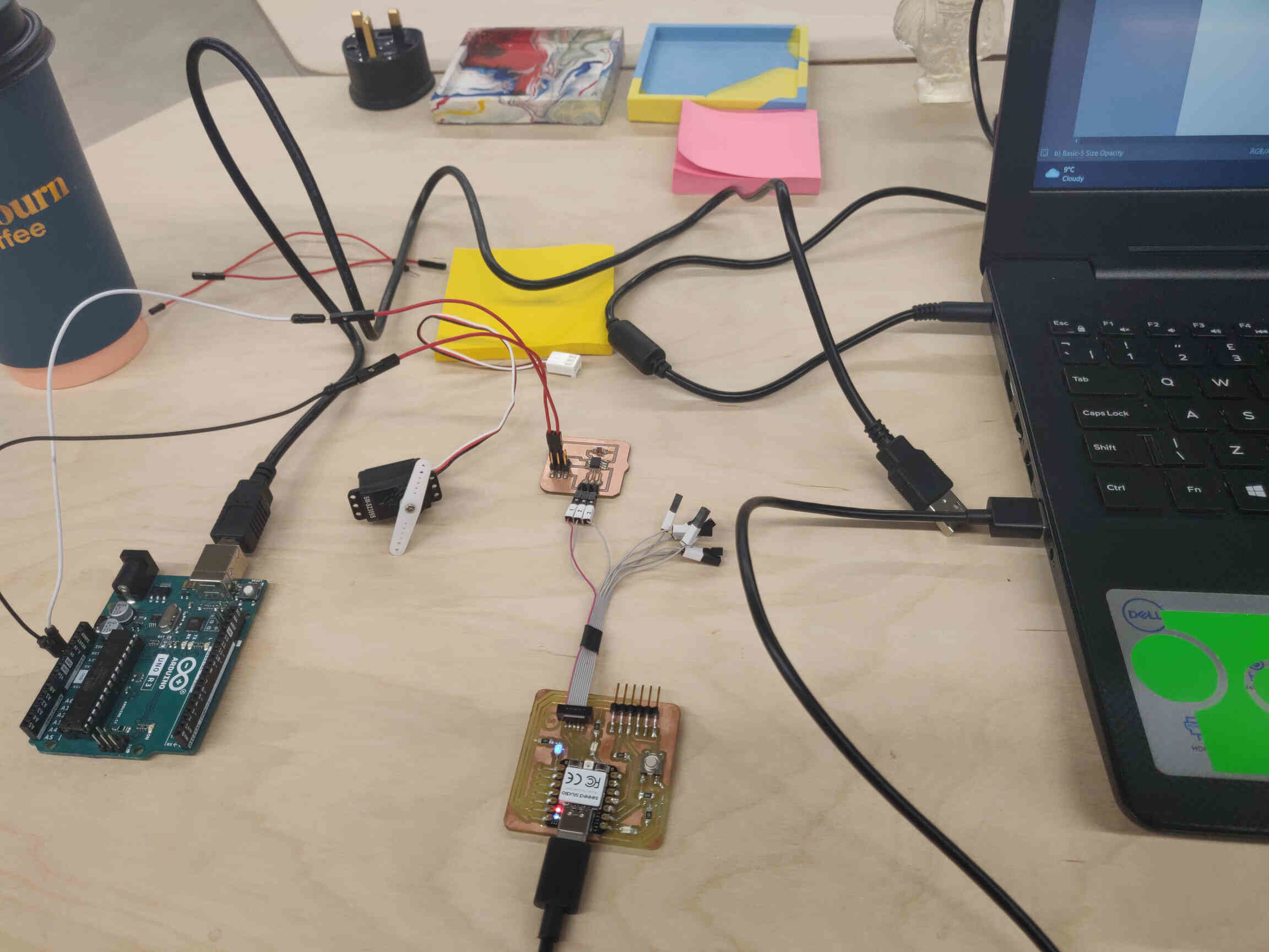
Servo Control & Code
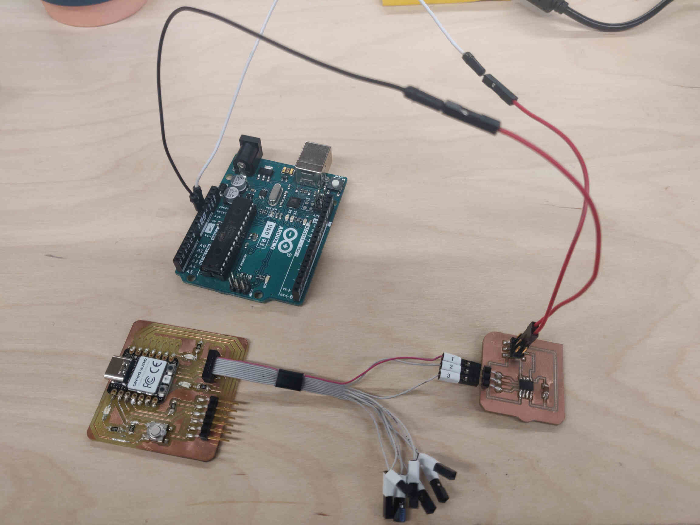
After discovering that we can use the Quentorres to control the servo motor, we had a look at our Quentorres board and saw what was faulty. We discovered that 2 of the 3 LED lights on the board were not working. One of the LED lights may have been damaged during the older soldering process, but the other one just needed more soldering to bridge the gap. So I re-soldered the board to fit in the new header pins - soldering them directly to the Seeed Xiao RP2040 microcontroller. This ended up working quite well and my board was functional once more.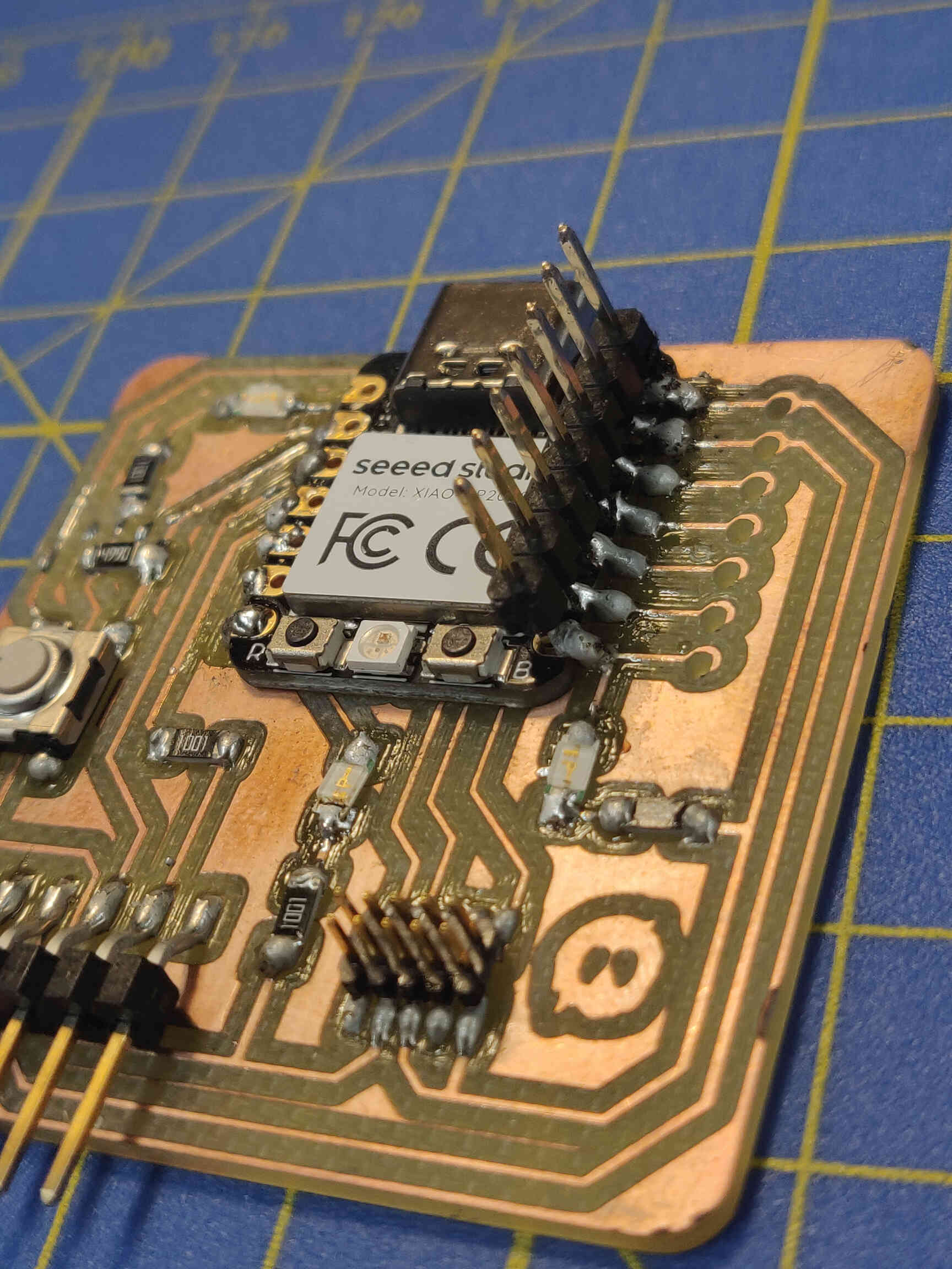
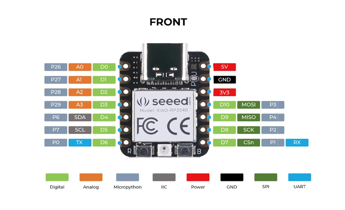
Connecting the RP2040 to my laptop using USB-C, then connecting Seeed XIAO PWR 5V to the Servo 5V, then connecting Seeed XIAO GND to the Servo GND and PIN3 to the Data, everything seemed all set up and ready.
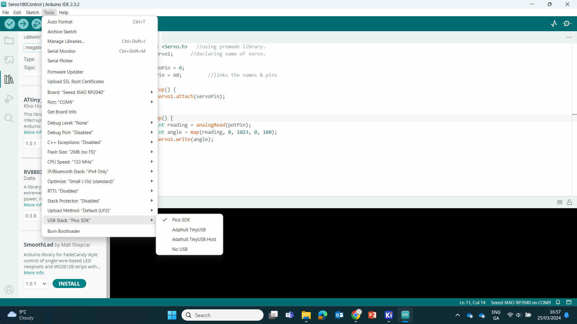
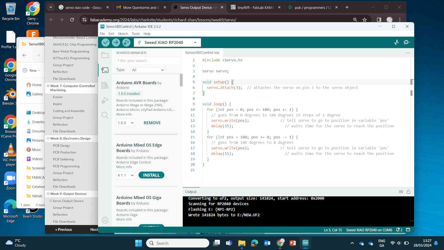
Then I put this code into Arduino IDE:
Servo myservo; // create servo object to control a servo
// twelve servo objects can be created on most boards
int pos = 0; // variable to store the servo position
void setup() {
myservo.attach(3); // attaches the servo on pin 9 to the servo object
}
void loop() {
for (pos = 0; pos <= 180; pos += 1) { // goes from 0 degrees to 180 degrees
myservo.write(pos); // tell servo to go to position in variable 'pos'
delay(15); // waits 15ms for the servo to reach the position
}
for (pos = 180; pos >= 0; pos -= 1) { // goes from 180 degrees to 0 degrees
myservo.write(pos); // tell servo to go to position in variable 'pos'
delay(15); // waits 15ms for the servo to reach the position
}
}
VIDEO SECTION
Quentorres / Servo Result
— — —
Conclusion/Reflections
For Output Devices week, my instructor and I made the decision to focus on Servo motors as it heavily relates to my final project. In my research, I made the attempt to have an analog dial control Servo direction, though later Oscar explained that I’m diving ahead into Input devices week and recommended I focus on controlling the servo motor without an Input device.
I created a new PCB in KiCAD following the AtTiny ‘hello.servo’ diagram found in this week’s assignment sheet on the Fab Academy Site. The PCB was milled smoothly without issue - my experience at handling the CNC milling machine has definitely improved. At one point it was a several day long mission to get something milled & working - now it only takes me less than an hour. Though I need to research how to create thicker trace lines as the tactics I employed this week still didn't improve the reliability of the traces.
There was a lot of difficulty in programming / turning on the PCB once again. This was the third week that I couldn't complete my PCB assignment because of debugging / programming issues. It finally got to the point where I needed Oscar to send an email to fab Academy asking for direct help.
From this request, it was revealed that a lot of students are focusing on using a Seed Studio Xiao RO2040 microcontroller as it doesn't require activation since it's already set up straight out of the box.
With this in mind, we moved from the AtTiny back to the Quentorres PCB and revisited the issues surrounding it. I got to work on resoldering and programming and eventually got it to control a servo motor - which was my goal for the weekly assignment.
Electronics / Circuitry is certainly not my strong suit, but I'm definitely learning bit by bit overtime - just not quick enough to complete PCB-related assignments. It also adds the most stress but I need to find a way to not let it get to me. Hopefully this will improve in the future.
____________