Group Assignment
Group Assignment Link:
____________
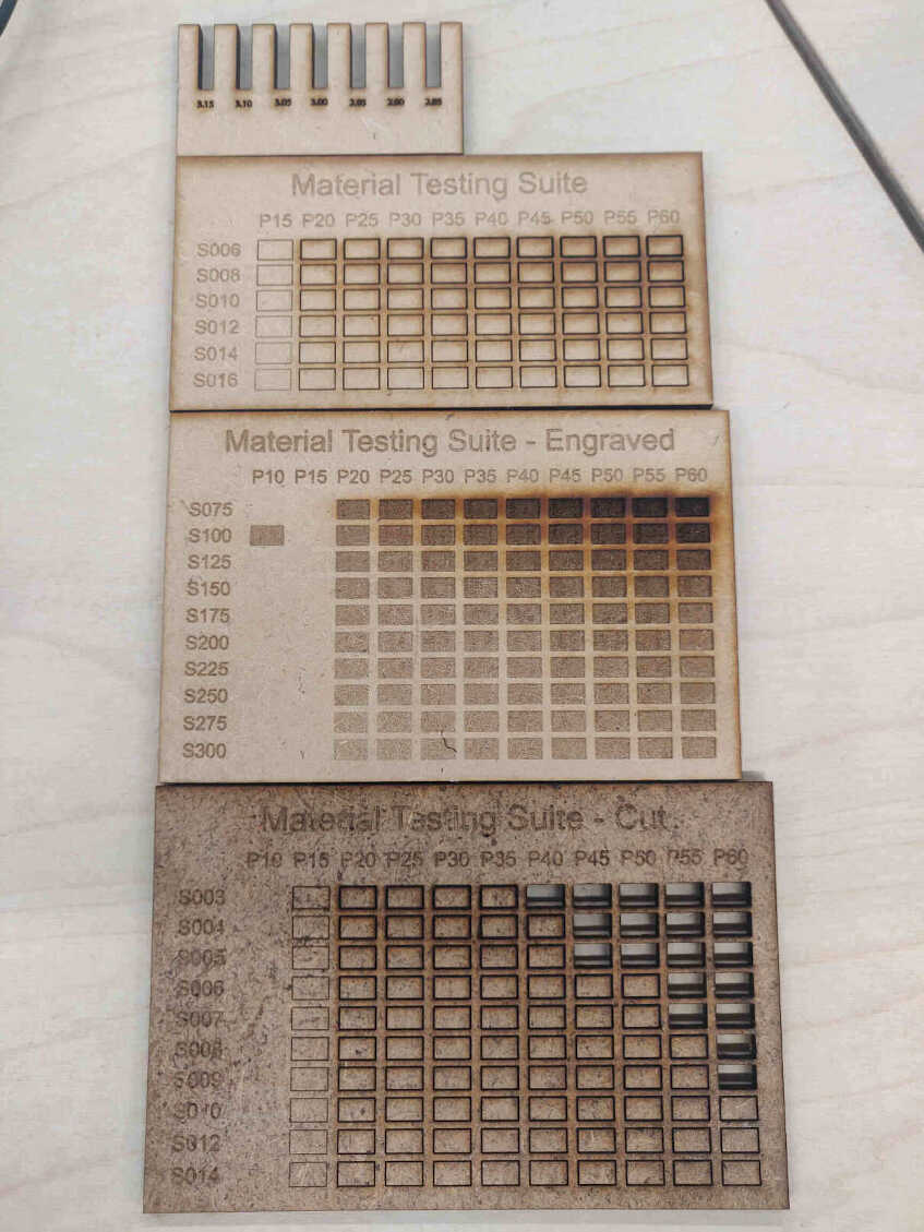
Laser Cutting Tests
The design for the Press Fit group assignment was designed and manipulated from Rhino.
Before cutting the Press Fit, I needed to do the Engraving & Cutting Tests.
All tests and parametric designs intended for laser cutting were imported into Beam Studio.
These test templates could be found in Beam Studio by selecting:
File -> Examples -> Engraving Test / Cutting Test.
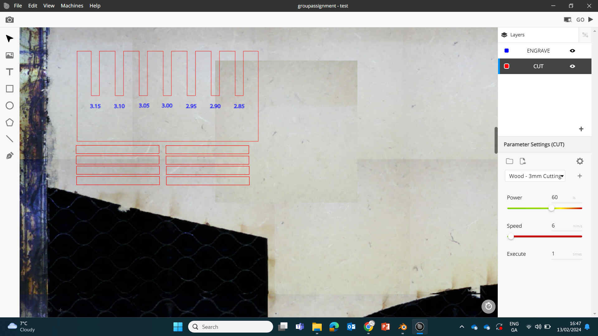
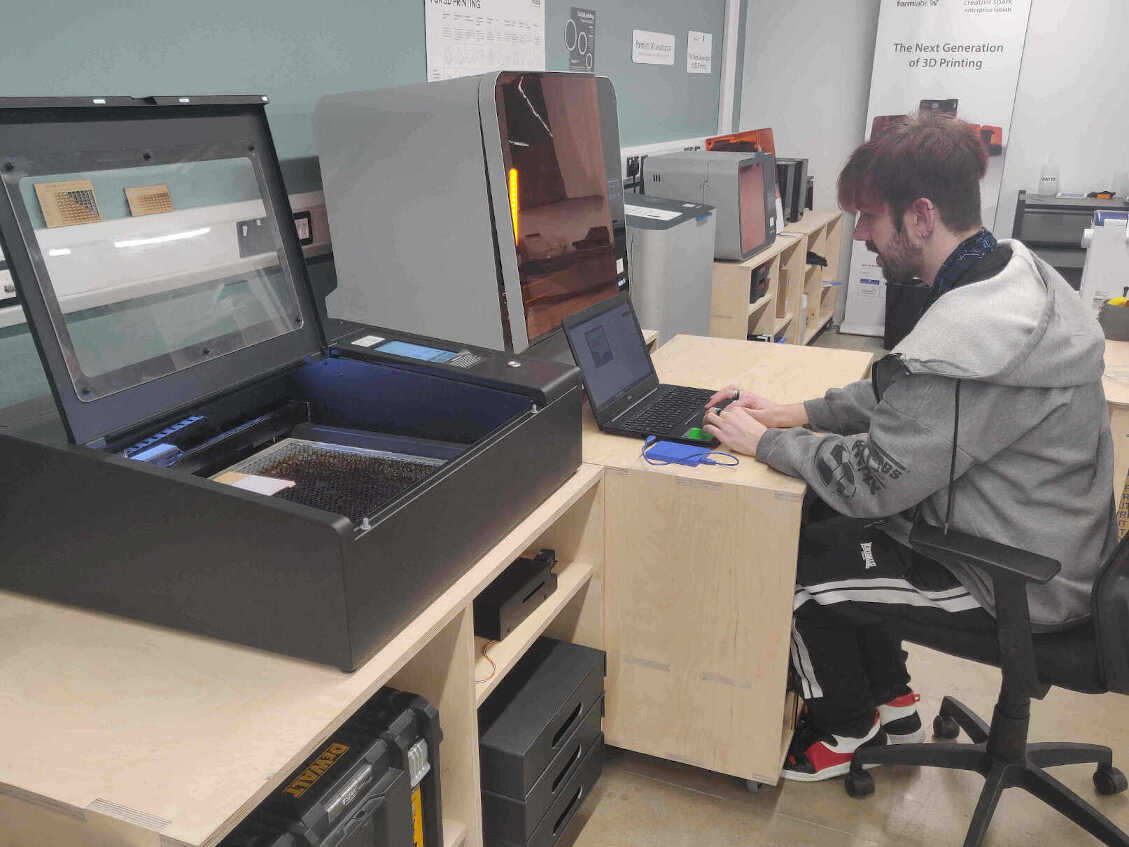
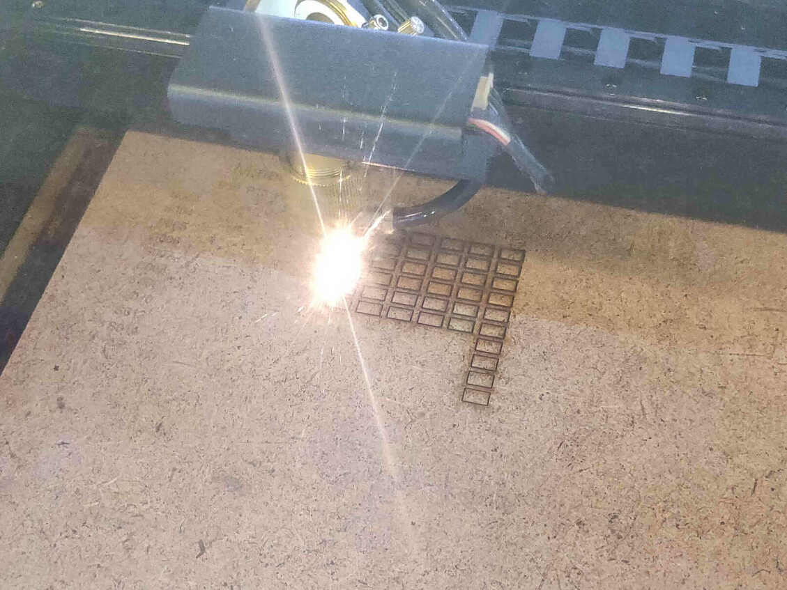
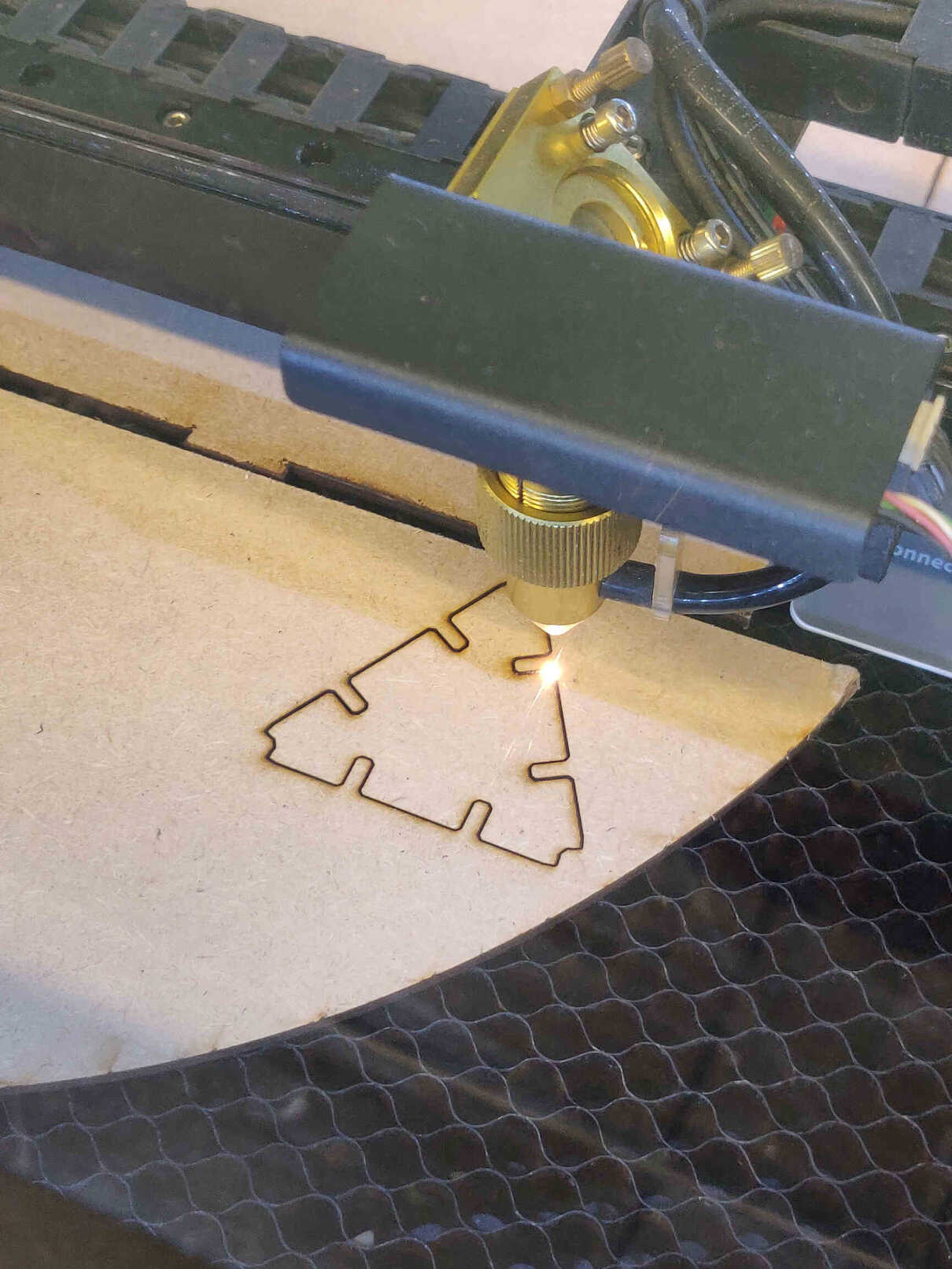
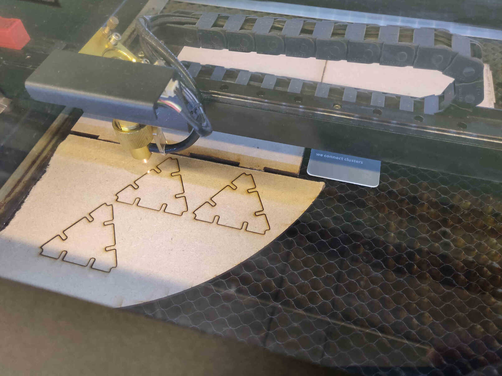
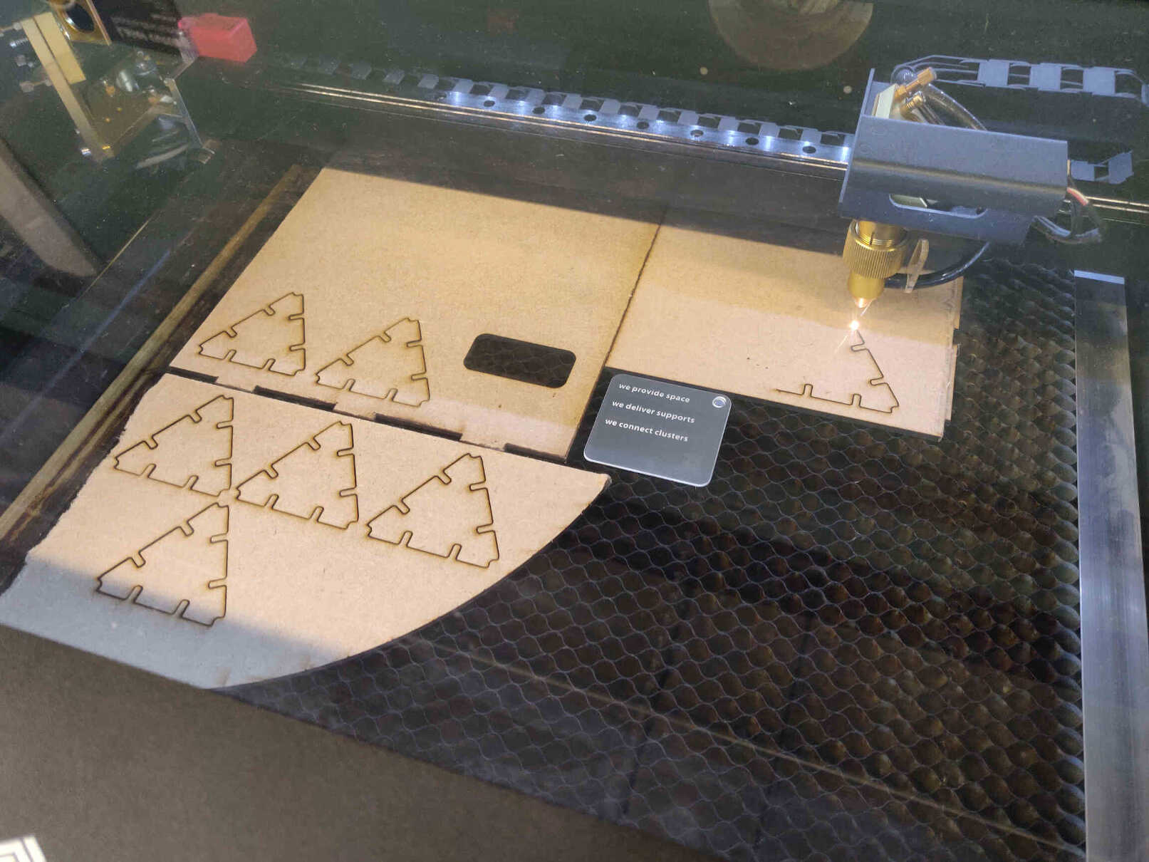
From here it was a simple process of correctly placing the MDF into the machine plate, laying out the SVG designs, carefully watching over the machine during the process (in case of fire), and examining the results.
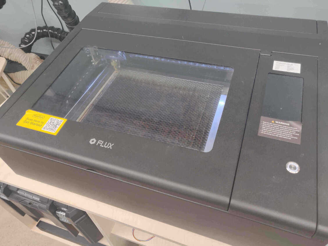
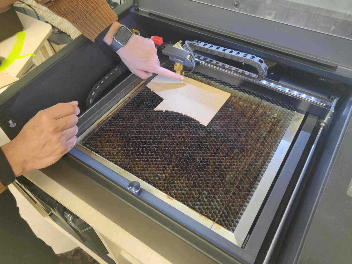
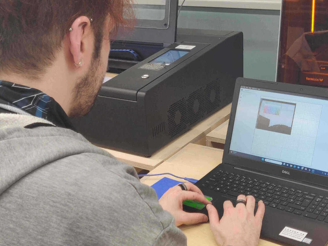
Photos of Laser Cutting Process
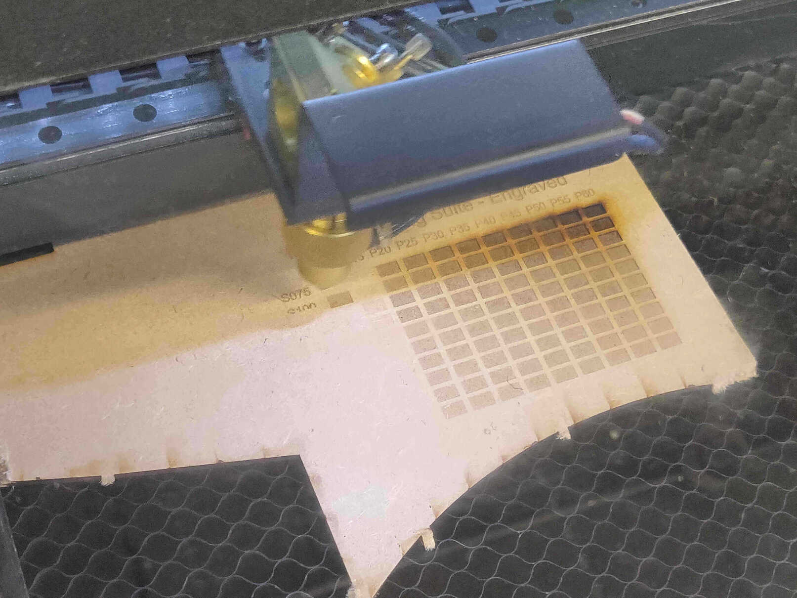
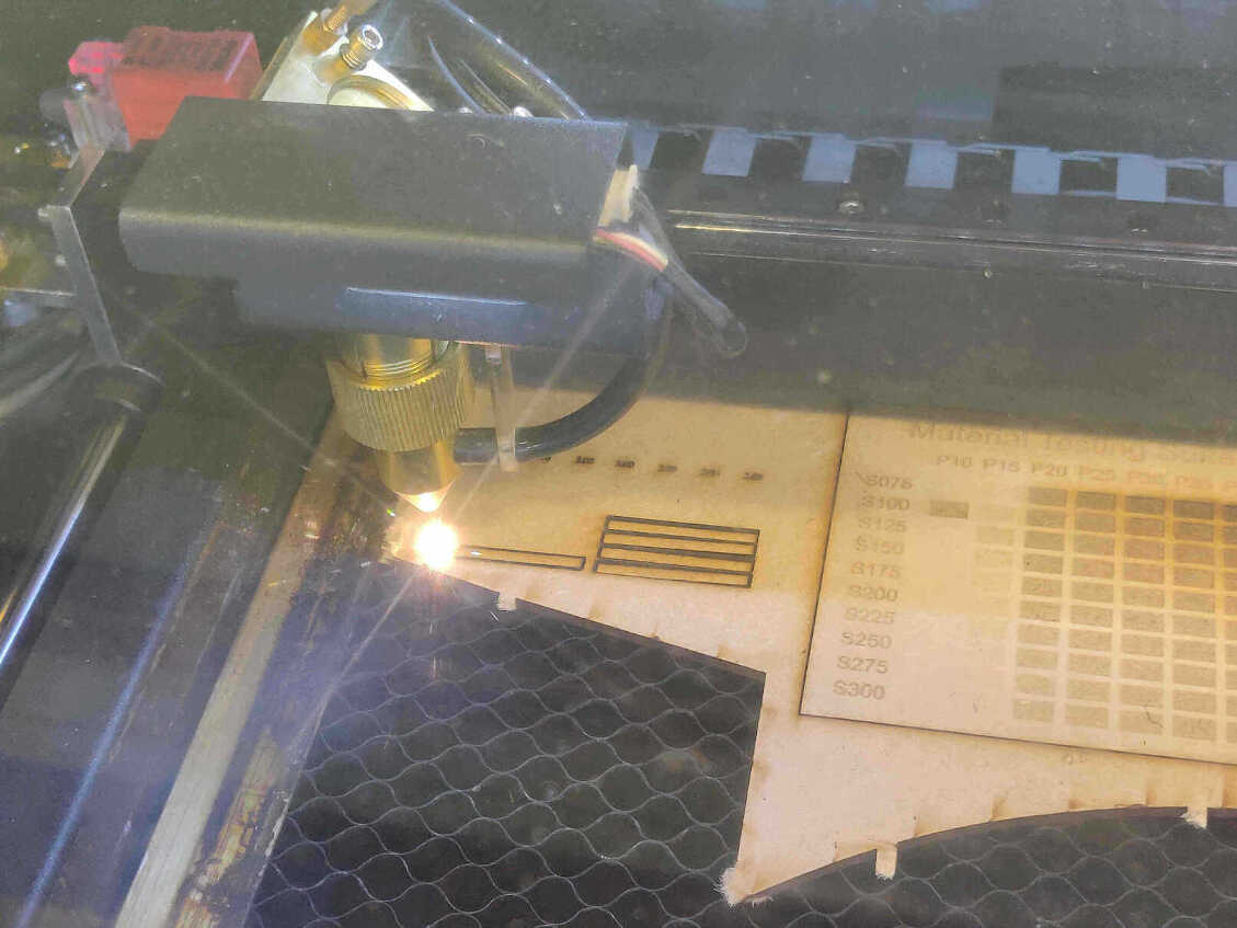
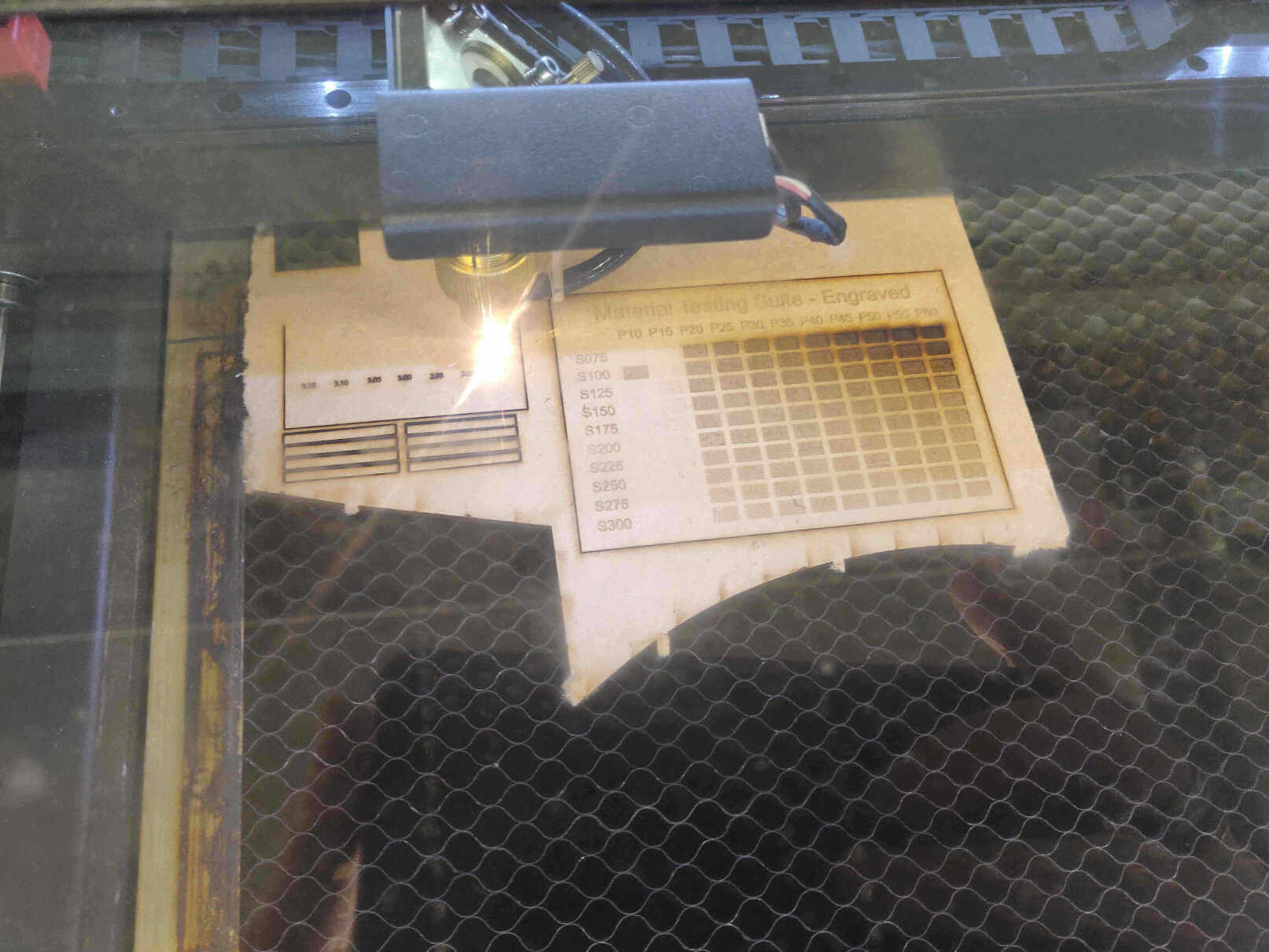
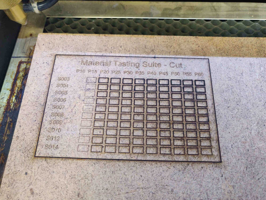
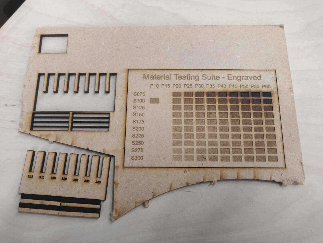
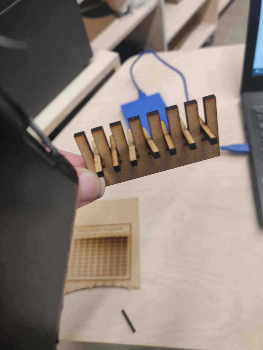
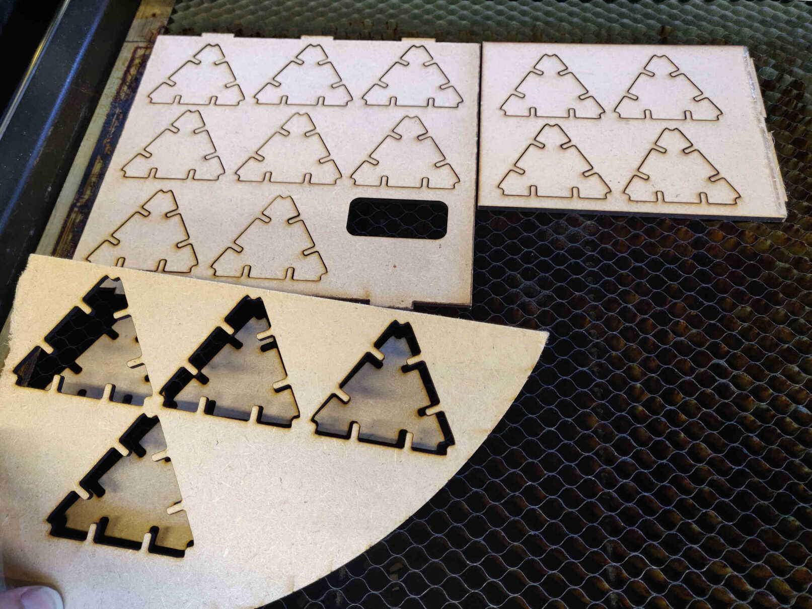
Laser Cutting Results
Tests for cutting, engraving & PressFit slotting and were ran successfully by the group.
____________
Individual Assignment
____________
Wednesday Meeting Reflection
I got called out for not compressing images before committing. I was uploading images inconsistently as I was still organising files as well as developing the look and style of my web design, with my intention being that I could just 'replace' the uncompressed images later. I was worried that may be an issue for Gitlab's repo in case it decided to save and keep all my date, but now it’s confirmed as that's exactly what the repo does. I need to focus on compressing all my images before committing, otherwise the repo will fill up.
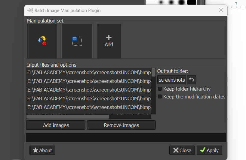
This was my first objective this week and with GIMP's BIMP addon, as well as WEB IDE's replacement feature (Ctrl+F), this was a breeze. I shouldn't have any issue with huge image files anymore.
____________
Previous Waterjet & Laser Cutting Experience
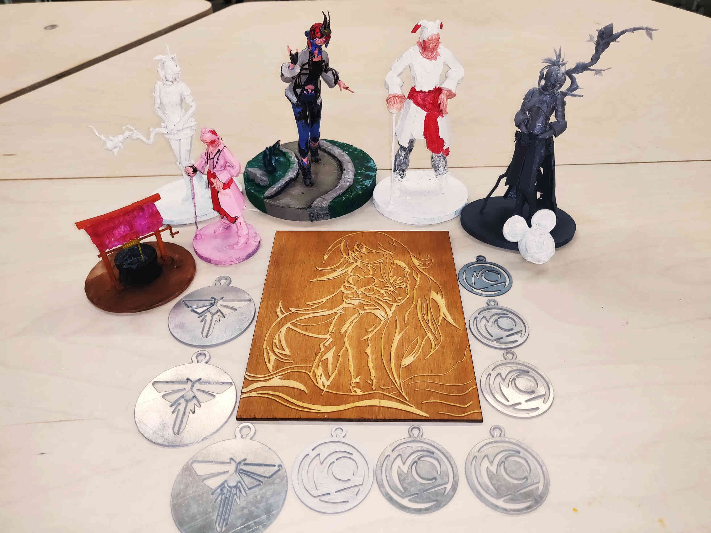
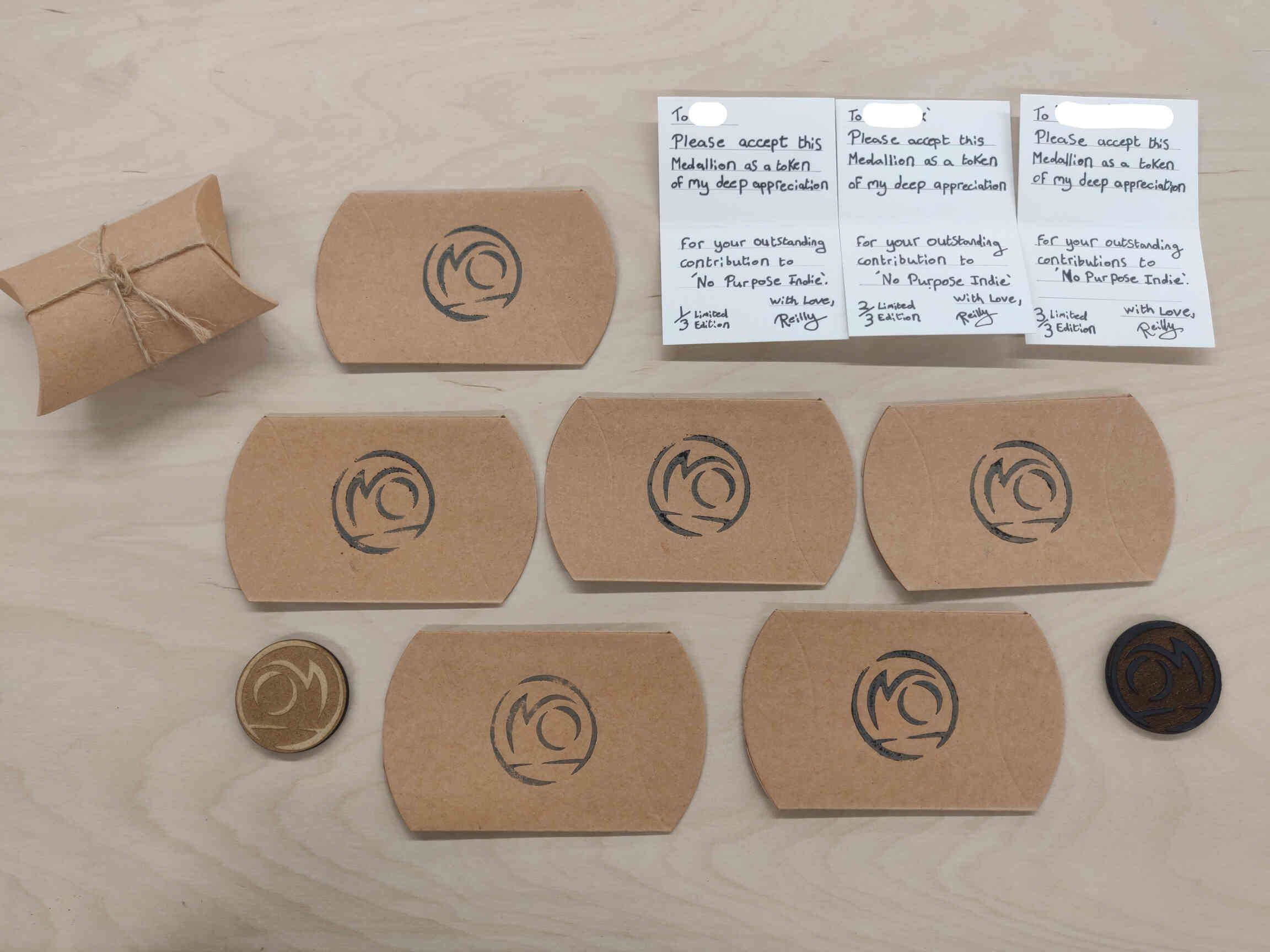
Medallions & Monoprinting
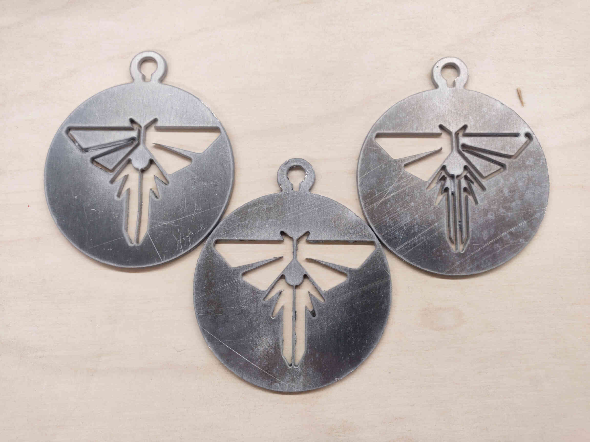
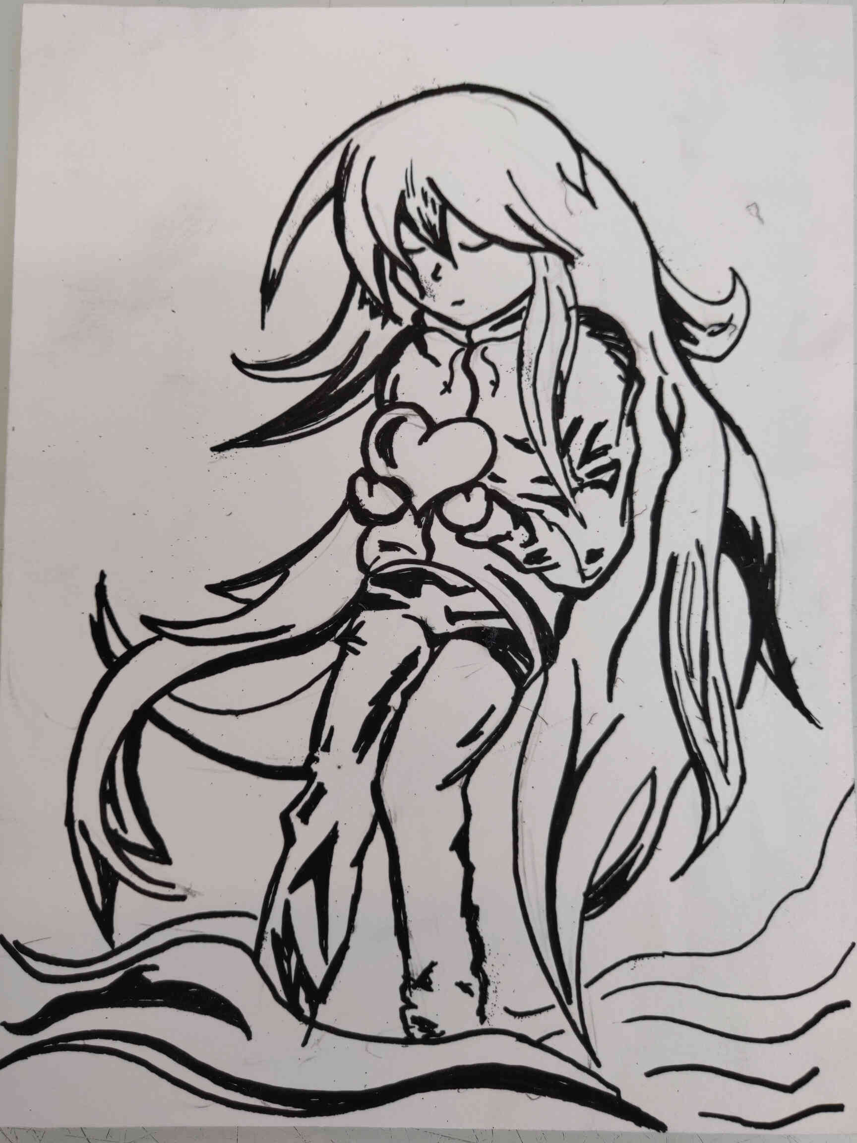
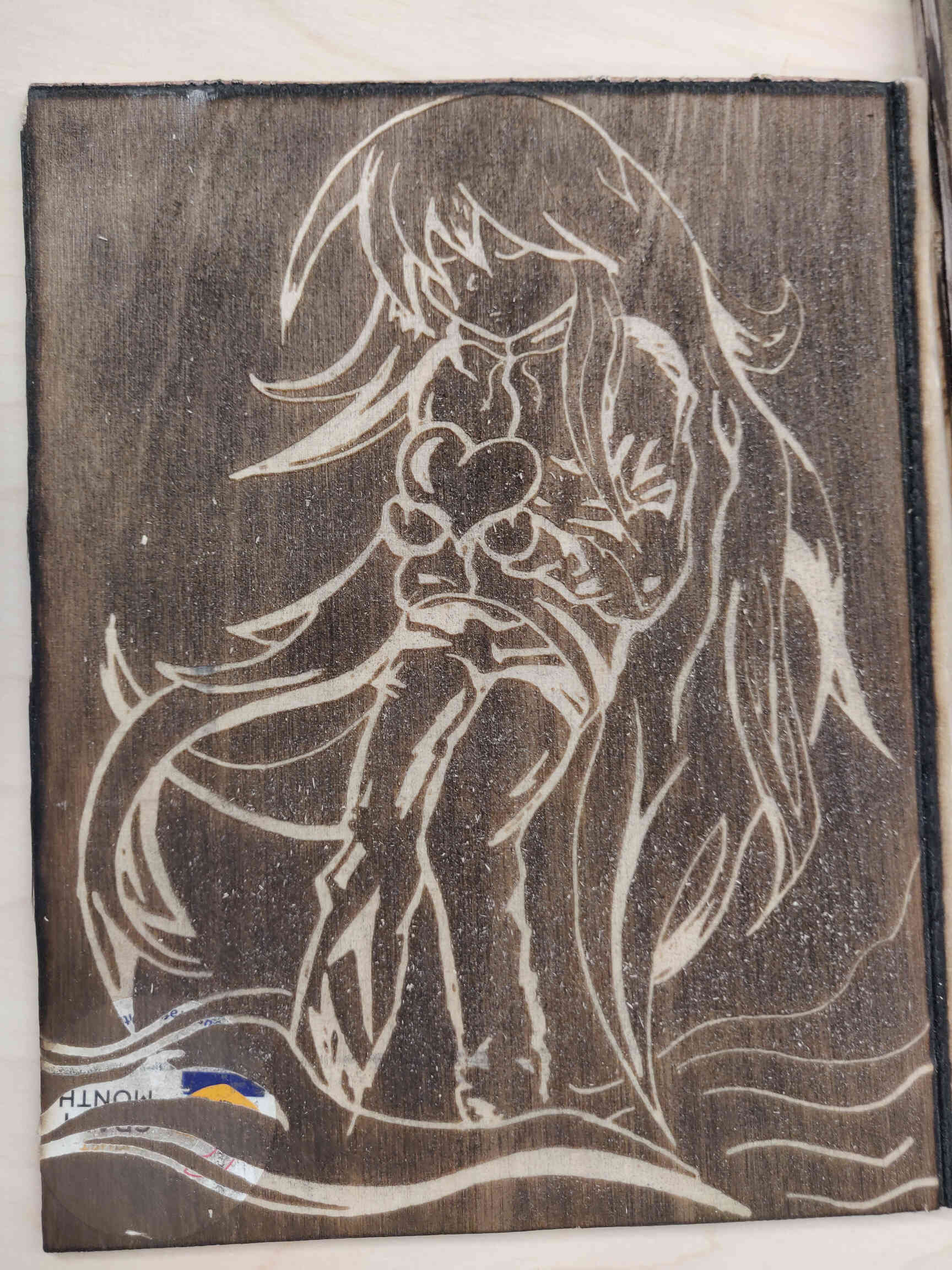
This week is all about Computer Controlled Cutting. I have some minor experience in this as you can see below. Not too long ago, I discovered the Wazer Water Jet Cutter and wanted to cut out Firefly Medallions (The Last of Us, 2013), as well as medallions with my own logo cut into them so that I could send them to my supporters. While working in a Print Studio part-time, during our Screen Printing classes I drew a design of Madaline (Celeste, 2018) in black marker and had it engraved onto plywood so that I could monoprint the design.
Here are the results ->
In terms of what machines I have access to, Creative Spark Dundalk Fablab has:
____________
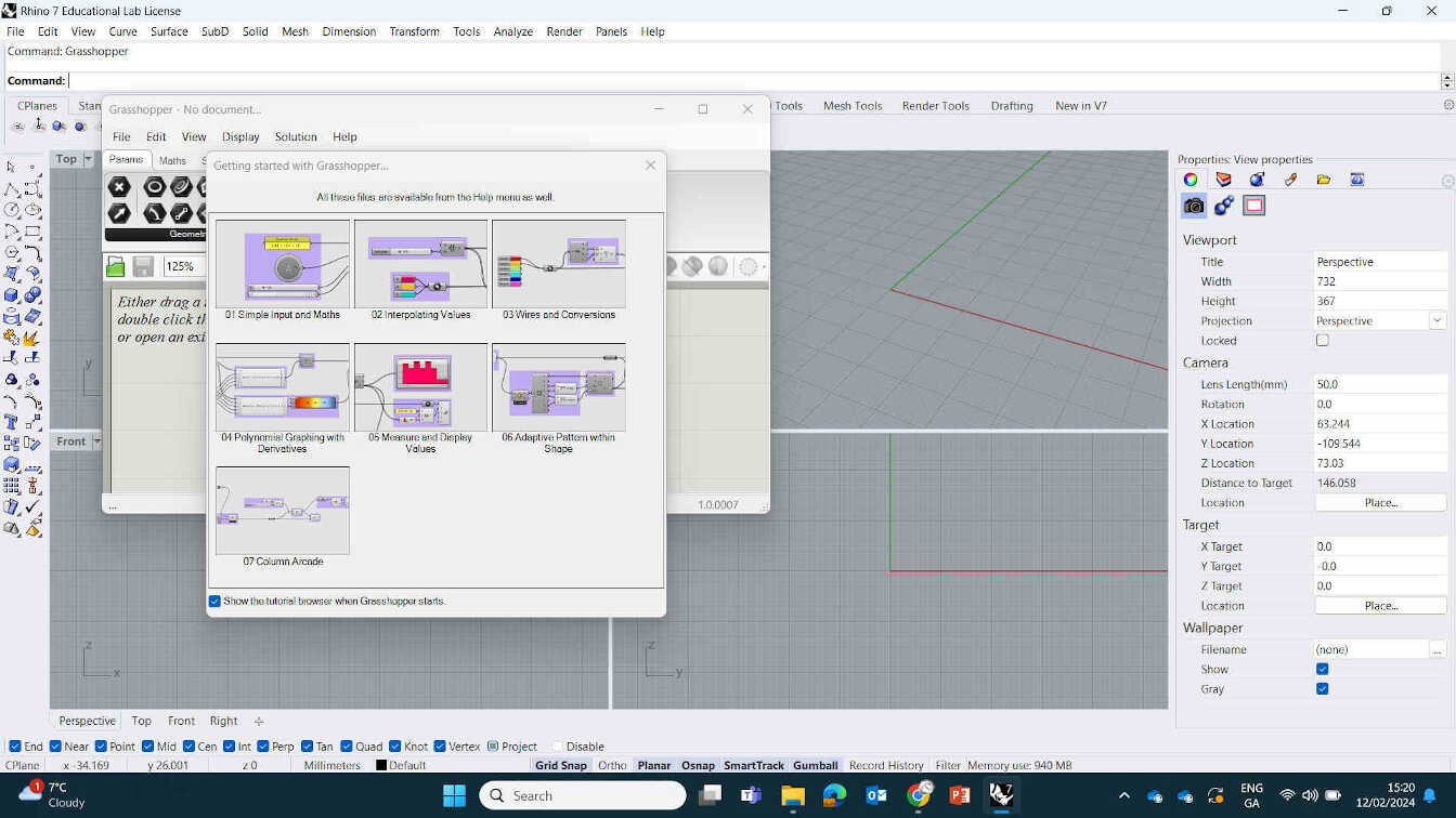
Grasshopper lesson with Instructor Oscar Diaz.
Creating Circle & Triangles using Nodes.
Grasshopper is a large addon for Rhino that allows for CAD design through the use of Nodes and Algorithms. Oscar took gave me a lesson on basic programming using these Nodes and Algorithms.
This was a field of work I tried to stay away from as I always found the mathematical process too difficult to understand. But during this lesson he did a great job at helping me understand it, starting with 2 simple tasks:
Node designs in Grasshopper and other platforms are created and manipulated entirely through Algorithims.
Breaking the structure down to:
Inputs -> Instructions -> Output
How to make a Circle? Give it the inputs / formula to make a circle. Formula for making a circle would be “Pi x Radius Squared”.
He showed me a book named AAD (Algorithyms-Aided Design) that he described as “the Bible of ADD” as well as "Food4Rhino", the site to access plugins for Grasshopper & Rhino. Grasshopper is found inside Rhino. Plugins can be installed and accessed in Grasshopper, for Grasshopper. Directing me to “Grasshopper forum” which is the main site used for questions, ideas, explanations & answers on anything Grasshopper related. Worth keeping in mind that Grasshopper works in Units and Rhino works in the Metric/imperial system.
The Layout is broken down to 3 main sections:
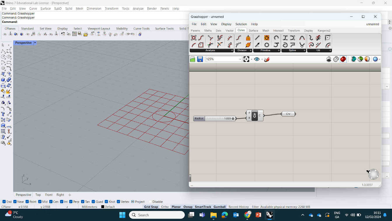
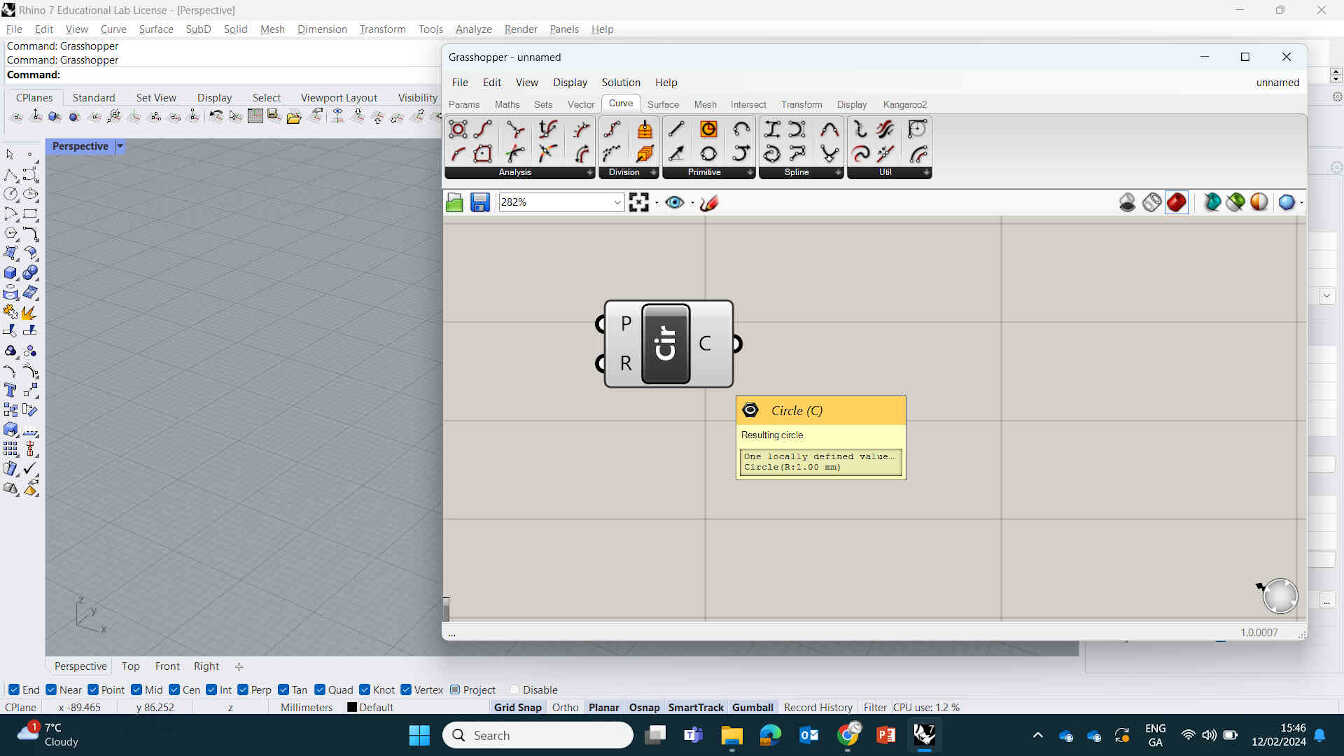
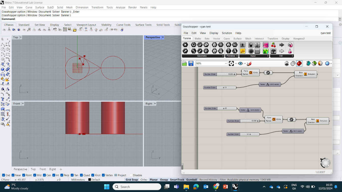
Making a circle: Get a "number slider" node and connect it to the Radius on the Circle node.
Right Click node or Double click to Edit. You can set minimum and maximum.
Add Curve node, and Bake.
Add a Extrusion node (found in Surface) to Curve. This allows me to Extrude the 2D design into a 3D Design. Go to Vector -> Z Unit Set number.
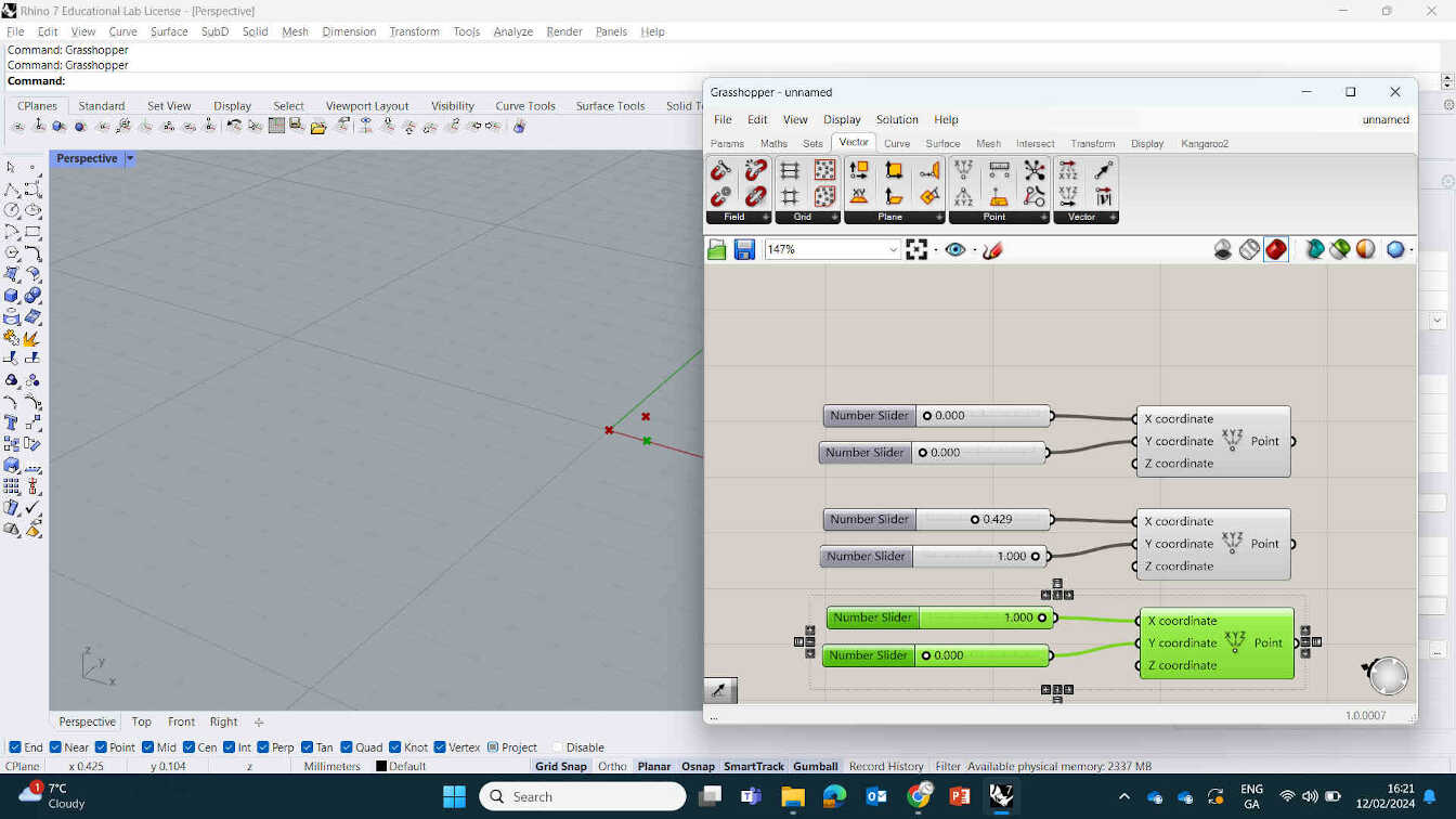
Making a Triangle: Was shown multiple ways of doing thios but I created a triangle by placing down 3 point nodes with their outputs connected to inputs of Line nodes. Then to connect them in the viewport, placed 6 number sliders connecting to the correct XYZ inputs of the Point nodes.
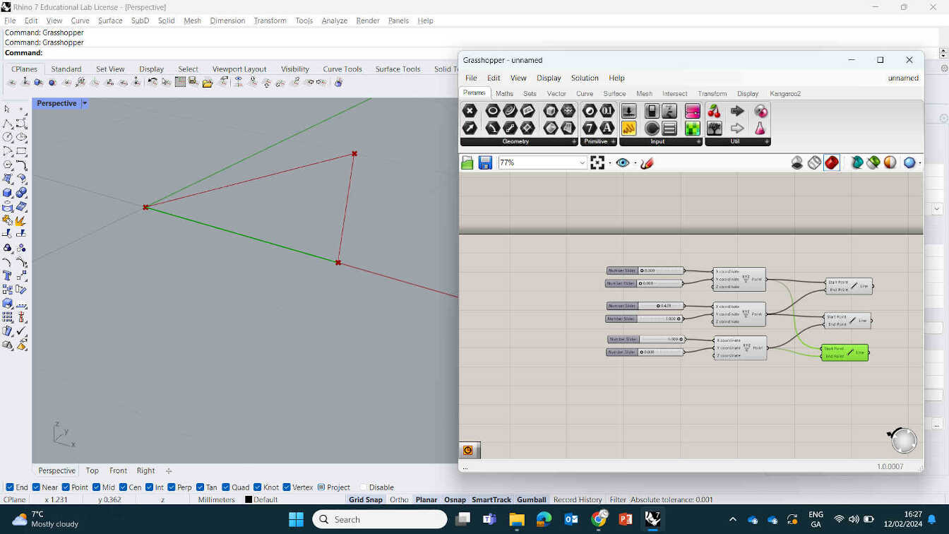
A cool key feature of Grasshopper is to Double click canvas for search bar, eliminating the need to scour through menus. You can copy and paste your design for duplicated objects and also 'drag select' nodes you want to be hidden and Right Click -> Preview Off.
It was a brief but revealling lesson on node based designs. I was still nervous about making something using nodes but Rico shared a Blender tutorial that can create a parametric design using geometry nodes, and I found it fascinating and easy enough to understand so I gave it a try.
____________
Monday Recitation
Quick dive into AI Tools
Currently in an AI Boom cycle where it’s become quite a disruptive thing in all areas - leading to a future where Students & Teachers are no longer necessary as they become obsolete. With this implication in mind, let’s just go ahead and see if we can make each class obsolete.
Some examples of currently available AI Tools include:
Chat.openai.com, text-to-cad.zoo.dev, Mistral as well as non-openAI.
For CAD Manufacturing there's OpenJSCAD and Python’s Pyvista. Using code to give it a basic understanding of the shape you want (Tables, Chairs, etc). This can also be done using LLMs (Large Language Models) for Computer Controlled Machining.
3D Scanning and 3D Modelling have sites with 'Text-to-3D Model' such as Threestudio, Genie and Luma AI. We saw a “Teapot made out of leaves” result and it didn't disappoint, with high detail and even strange imperfections that a Fine Artist would make. Myself and Oscar tested "Genie" tool see if it could make a "Ruler made out of Goat's Cheese". It did and gave us the option to download an STL file, but we thought for humanities sake, we'd best refuse.
AI Tools for Electronics Design let you drop in PDF’s of designs and schematics and openly ask the AI details and solutions within the PDF such as 'BoardDesignerGPT'. OpenAI(r) - used to make a sprite-based Fab Lab room with pixel art style. My mind was blown when I saw 'Htmaaland'. Imagining a world where we could simulate diploma courses within a pokemon/game-like setting, having our queries answered by AI in the form of our lecturers and students...
Speaking of which ->
We also discussed Implications, Limitations and Ethics. Current research involves Creating an AI student to complete Fab Academy assignments using only Open AI tools.
Open Source AI Tools. Using AI to document - Whisper Model, is a Speech to Text open model. Best Multi-platform: GPT4ALL
Zoom AI Companion Strategy:
Zoom Video Communication founded in 2011. Zoom Products = Video Meetings, chat, mail, document processing, etc.
Currently Zoom AI can support: AI Companion Questions - Ask Questions and get Quick Responses or summaries, etc. Core Technology behind AI Companion: Federate AI.
To get the best version of what you’re looking for, you must run it through every AI model at least once.
Model chain: A sequence of models with increasing performance and cost.
Z-scorer: Trained quality evaluator, to decide when to show the current result to users.
End of Recitation ended with mention of “Fab Futures - Vocational skills for tomorrow…”. Lasting 1 month per module starting in September 2011.
All digital information is Freely available. But costs will increase depending on services cost.
Involves Robotics, Video Game Development, etc.
Update: The day after this recitation, OpenAI revealed ‘Sora’, an updated video generation software that is remarkable in its effectiveness at seeming like real footage. No more Will Smith eating spaghetti! I’m all but assured I’ll be using this in the near future to create unique and personalised stock footage. RIP to Stock Footage jobs.
____________
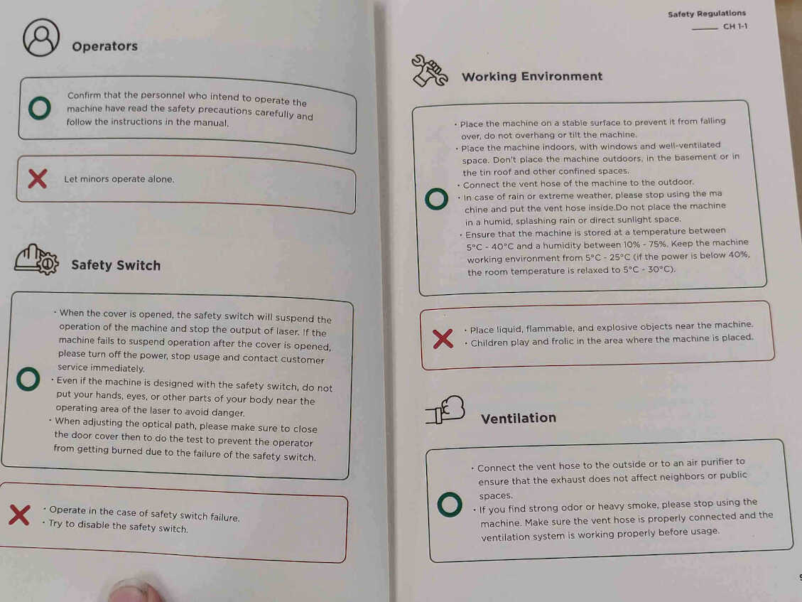
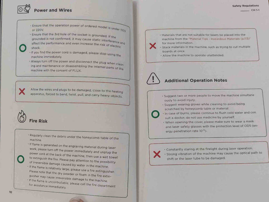
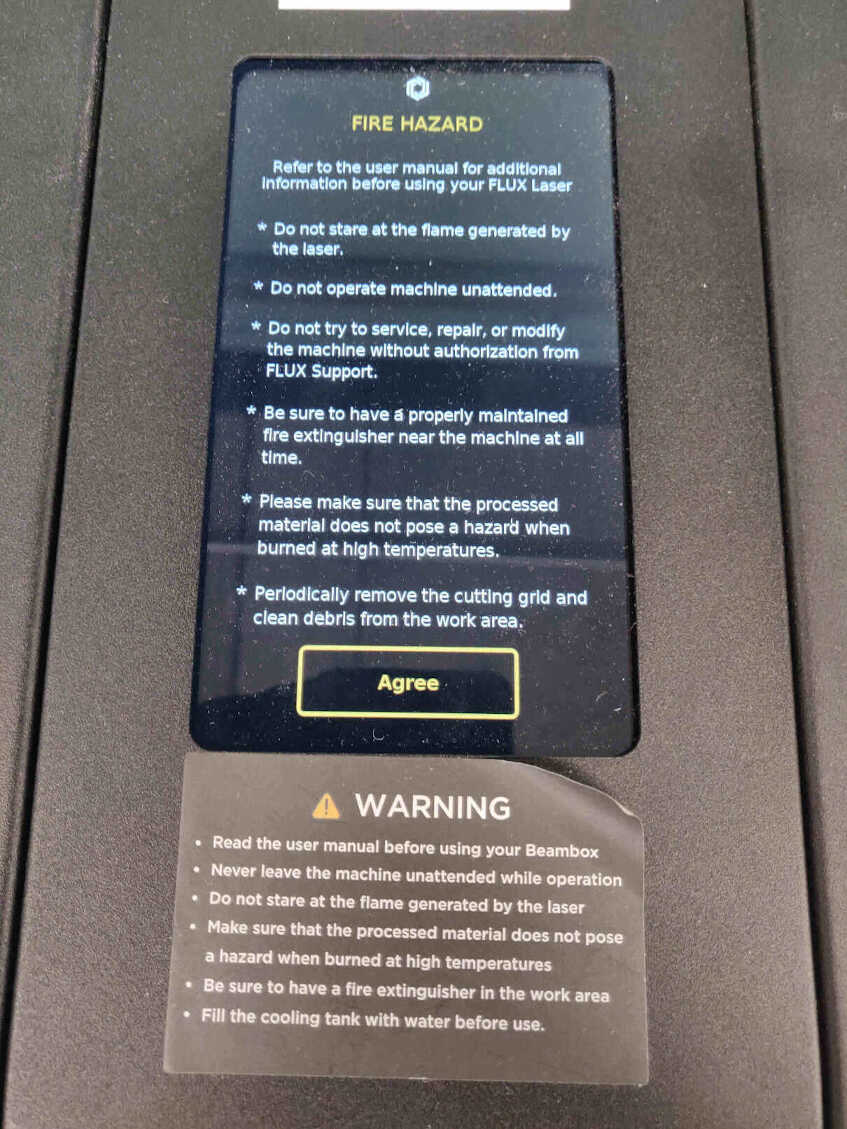
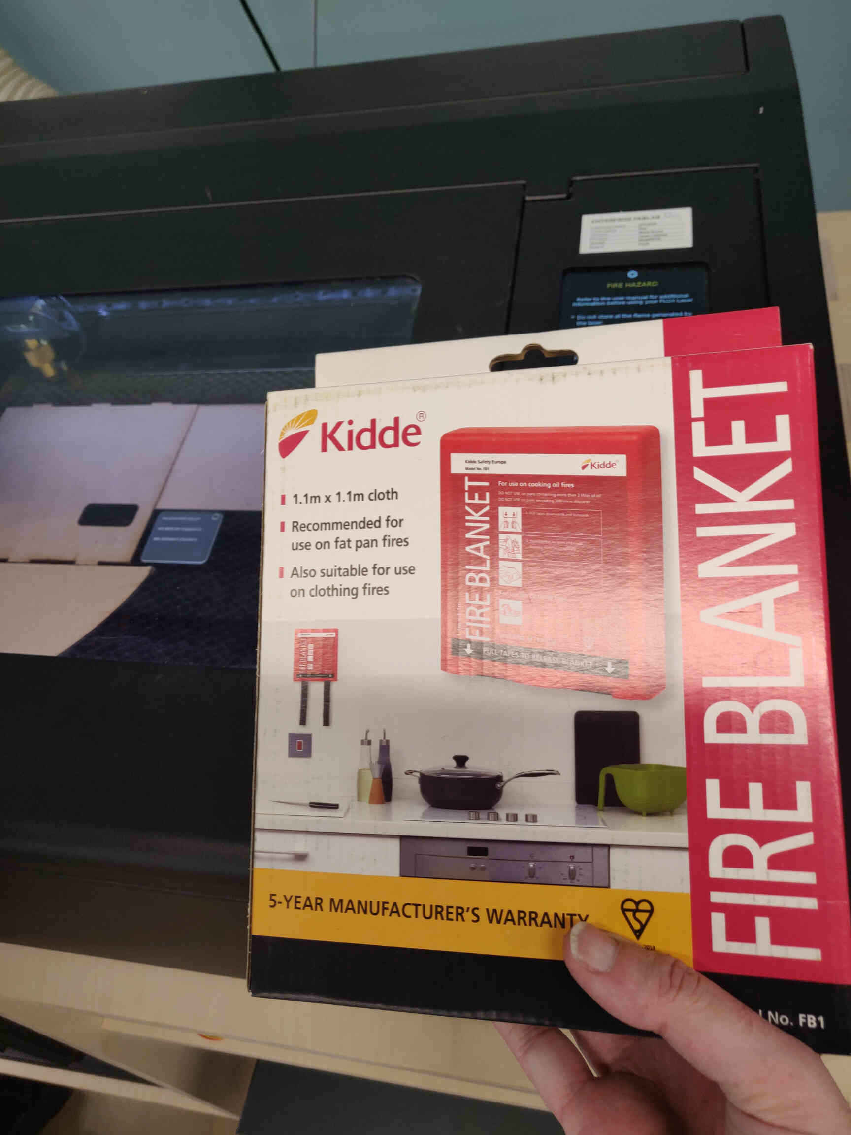
Laser Cutting Safety
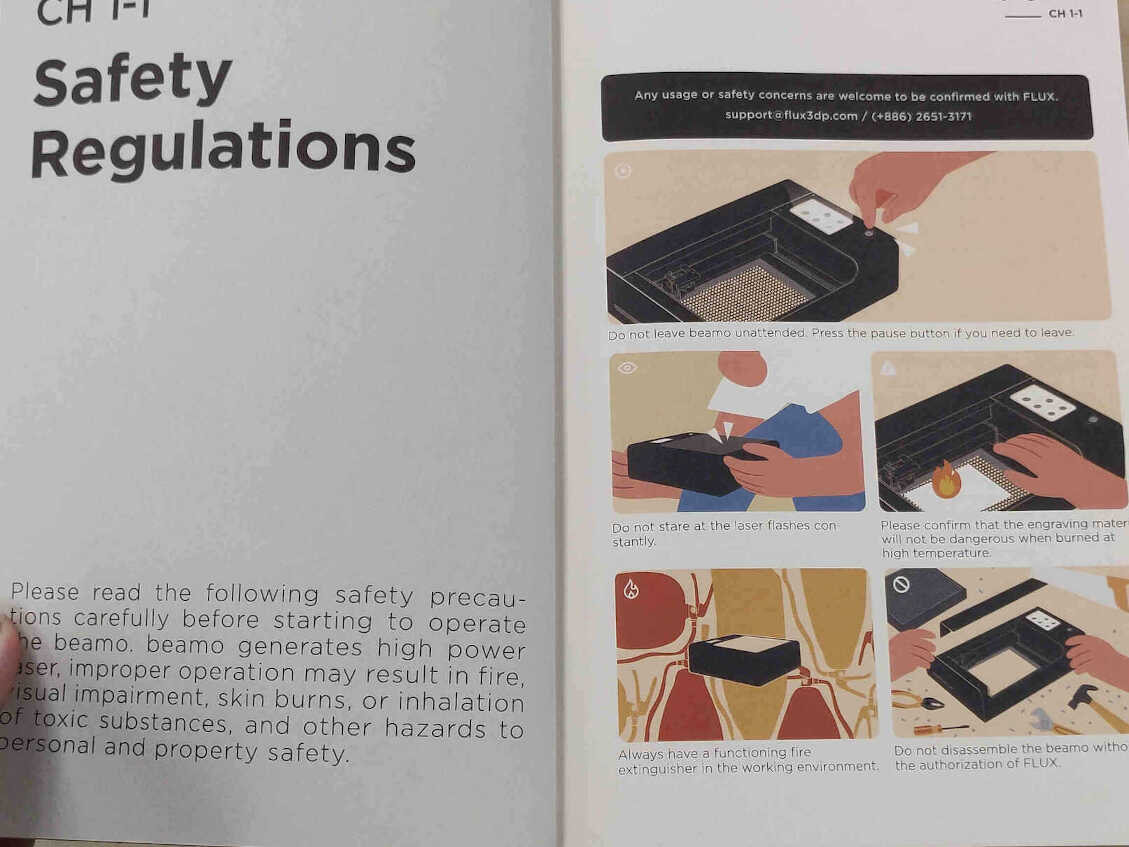
Before starting to laser cut, it's very important that we take a look at the necessary safety precautions. Directly next to the machines in my fablab was the 'Beamo User Manual' which highlights on the first couple pages exactly the importance of this. It's imperitive that I stay near the machine as it runs, being aware of sights, smells and sounds that might indicate a problem which may lead to a fire. I've taken pictures of the manual's safety guide for your convenience.
____________
Parametric Press Fit Kit in Blender Geometry
I was sent a link by Rico to a Press Fit Construction tutorial where you design your Parametric Design through Blender’s Geometry Nodes. I've played with Node Design in Blender & Davinci Resolve before but could never get the hang of it apart from basic colour grading, so this was a new challenge for me.
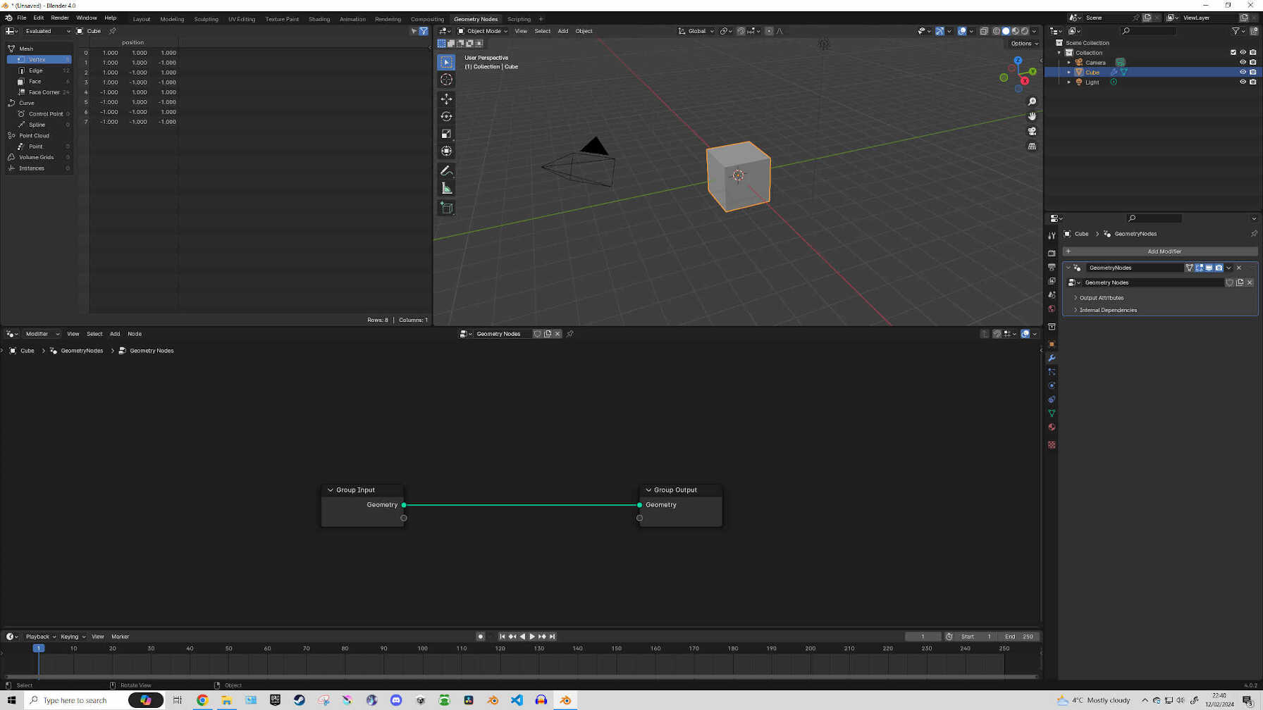
Starting off with opening Blender and clicking on the ‘Geometry Node Editor’ tab to change the layout into what we need. Select the default Cube and hit ‘+New’ in the Node Editor window.
EDITOR'S NOTE: I can’t fully explain everything I used and how it affected the shape as Node-Based design is still very new to me, but I can guide you through the steps I took as well as my process and my opinions on the changes.
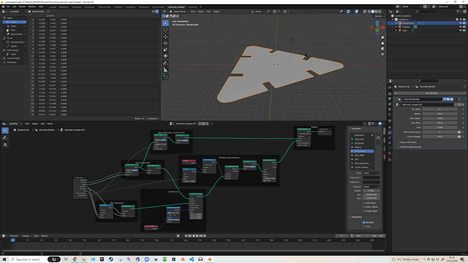
In the Node Editor, you can add components and nodes either by pressing SHIFT+A or Right Click the Editor -> Add. Starting off with a Curve Circle between the Group Input & Group Output nodes, this will break your Cube down to a flat circle. Connect the Curve Circle’s Resolution & Radius input node to the empty connection sockets under the Group Input node.
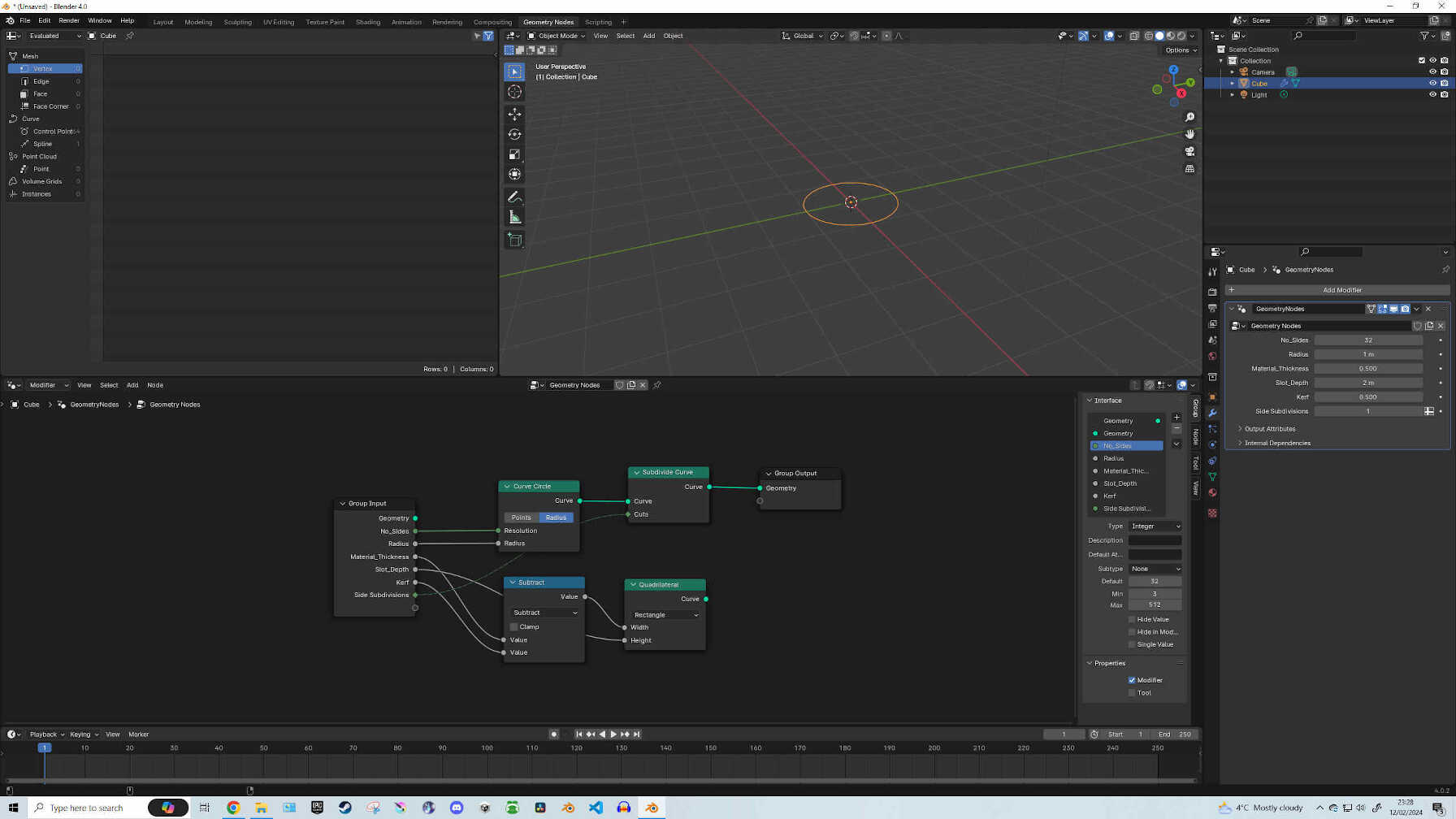
You can then rename these sockets to whatever you think they will be used for. This part confused me until further into the tutorial were I realized that these renamed connections would later become easily accessible parameters that can alter and customise your parametric design on the fly, such as changing Slot Width, Slot Depth, Number of Slots, Radius, Subdivisions, Corner Buffing & Kerf. These can be relabelled by pressing ‘N’ to open the Group Menu. After that is where Mathematics came into play. I added a Quadrilateral node, Subdivide Curve node and a Math node, then changed the ‘Add’ to ‘Subtract’ and made my connections.
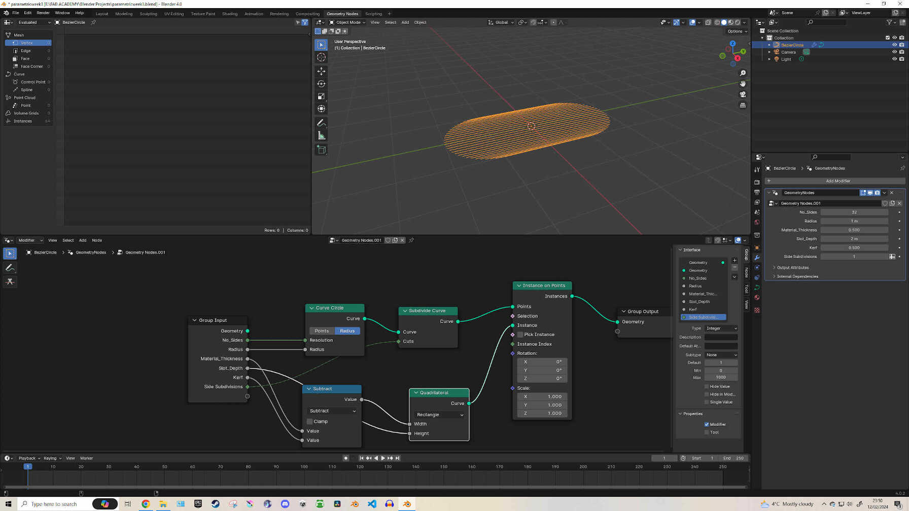
For instancing the slot geometry to the base geometry, I added an ‘Instance on Points’ node, ‘Align Euler to Vector’ node and a ‘Curve Tangent’ node and made my appropriate connections. These will allow us to manipulate the Slot Geometry to the correct perpendicular position on the sides of the Base Geometry. (For a more in-depth look at where to place these connections, please follow the link at the start of this guide to the tutorial I used - or just look at my node editor screenshots and replicate the connections).
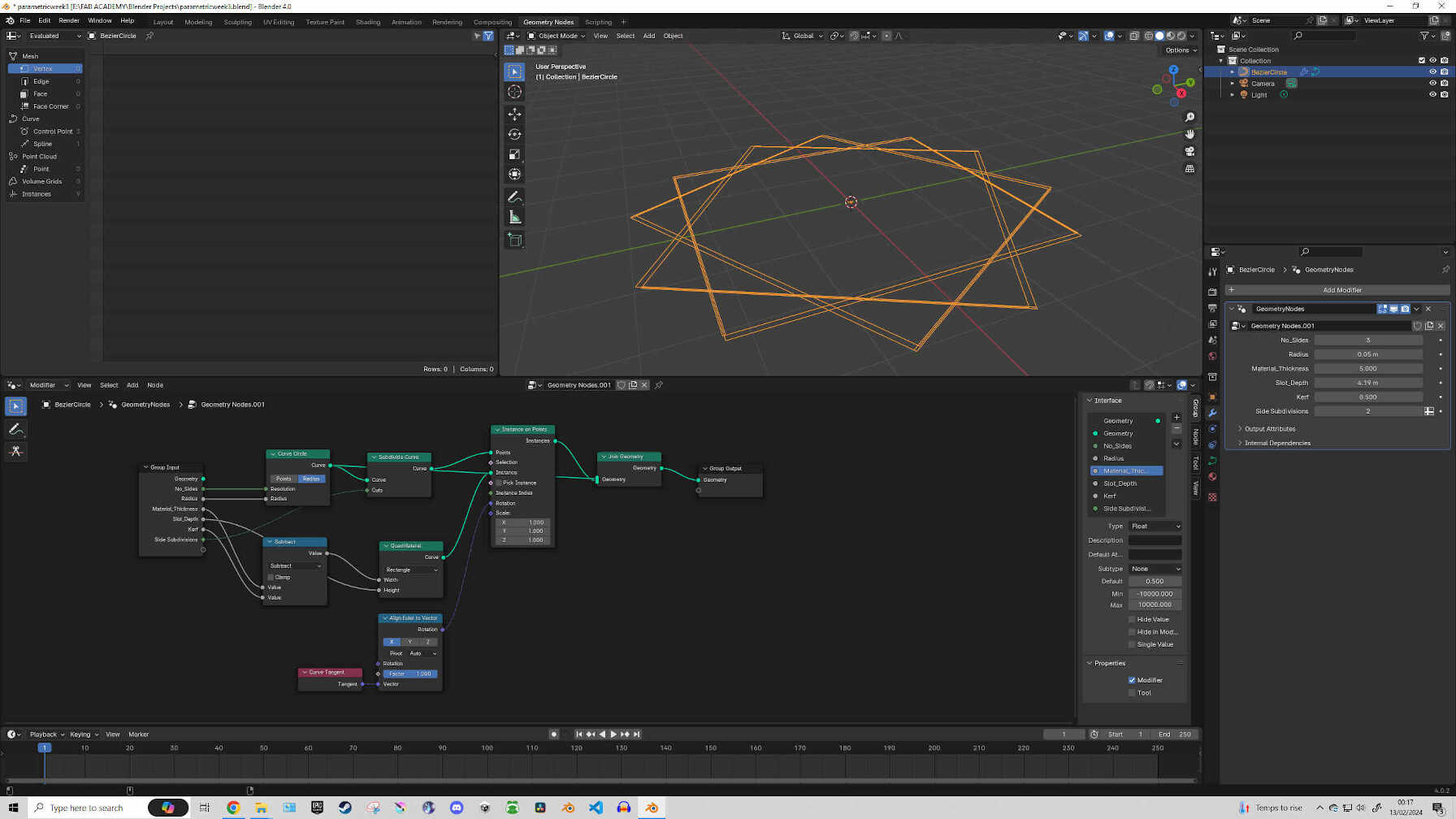
To preview the shape of your design, you can add a ‘Join Geometry’ node and connect it to the Curve Circle & Instance on Points nodes. This gives you the chance to mess around with the shape and settings to get a feel for it. But to continue on with our node-based design, we will need to delete the ‘Join Geometry’ node. Now add a ‘Fillet Curve’, ‘Fill Curve’ & ‘Mesh Boolean’ nodes. Toggle the Poly option on the Fillet Curve node and set the ‘Count’ to 5. Also Toggle the N-gon option of the Fill Curve node when available after making connections and set the Mesh Boolean operation to ‘Difference’ - This will cut our Slot Geometry into the Base Geometry.
At this point, (if all connections are made and the parameters are set appropriately), you should see your design as a empty Triangle with lines sticking out where the slots will be.
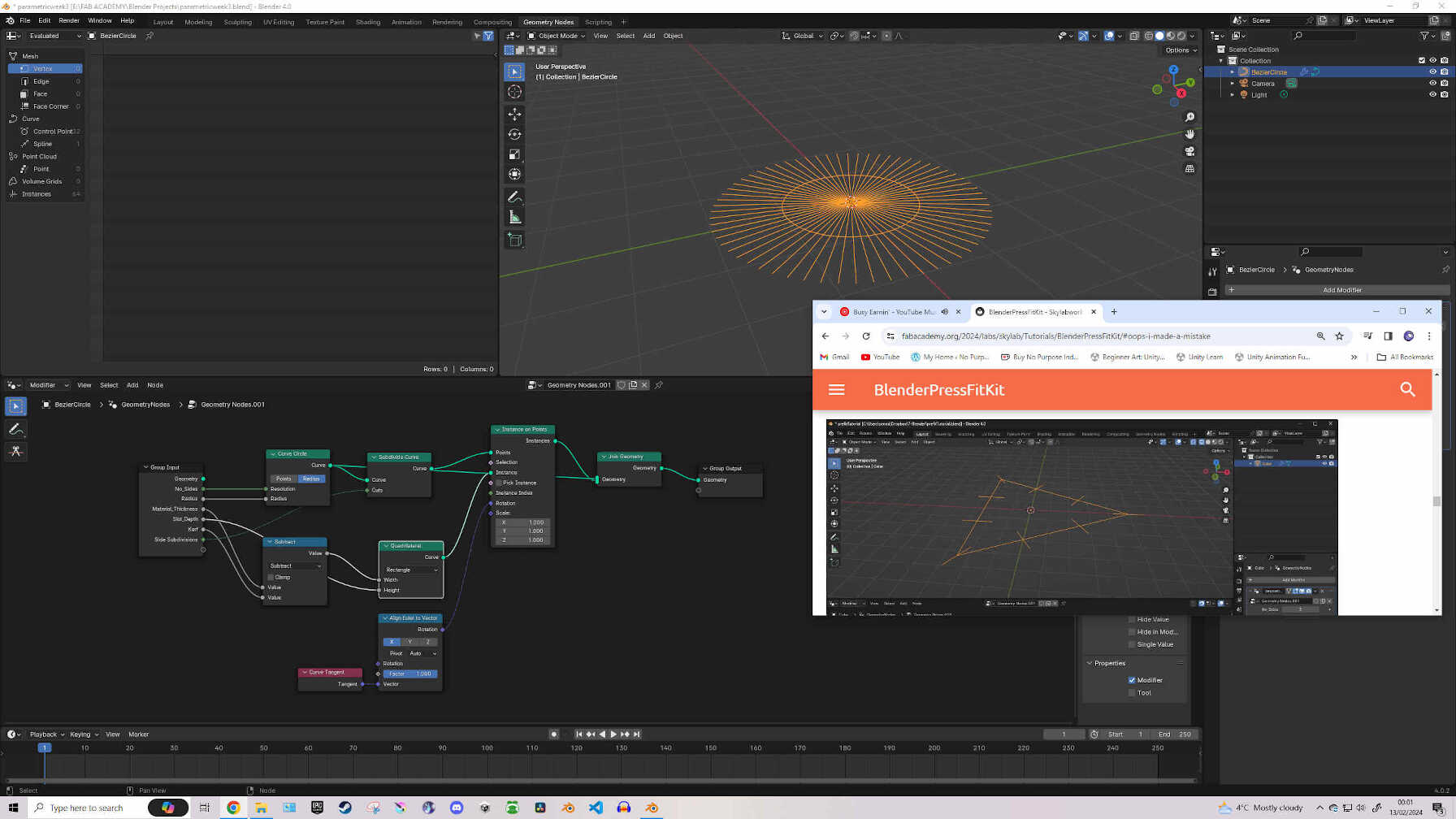
EDITOR'S NOTE: I followed the tutorial to the letter, yet there was something wrong. From the very early steps, he had a Hexagon design built, ready to be customized & manipulated. But my design remained as a small circle throughout most of the tutorial. I spent a good bit of time trying to find what's causing the issue, but it kept eluding me.
But I kept in mind, the best part about mode-based design is, if there is one little detail causing a problem in your design, once it's found & fixed, the flawed design will instantly transform into the correct design. Early mistakes won't cause a permanent flaw that would require starting from scratch - so I just continued on through the tutorial.
Eventually (around 60% tutorial completion) I messed with the measurement settings and found the issue. Blender set my radius far far too low from the get-go. Once I raised it up, my design started to take shape. When I did this earlier while the basic design was still taking shape, it was difficult to line up the measurements as the model preview was just scattered lines. Further into the tutorial, it was easier to match the design that was intended. I took a sigh of relief and continued on.
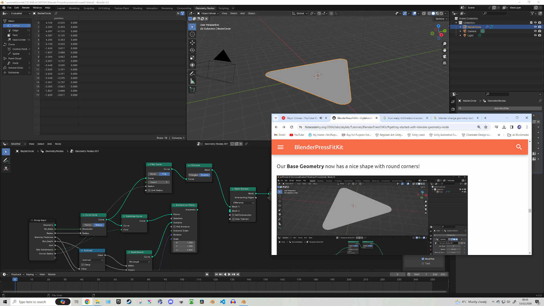
At this point, (if all connections are made and the parameters are set appropriately), you should see your design as a solid Triangle with rounded corners.
To clean up and organise my Node Editor, I added ‘Frames’ which are visible containers than hold several nodes that you believe are related to each other in the operation that you’re making. Once the Frame is placed, just SHIFT+CLICK your relative nodes and drag/drop them into the frames and label the frame with a name.
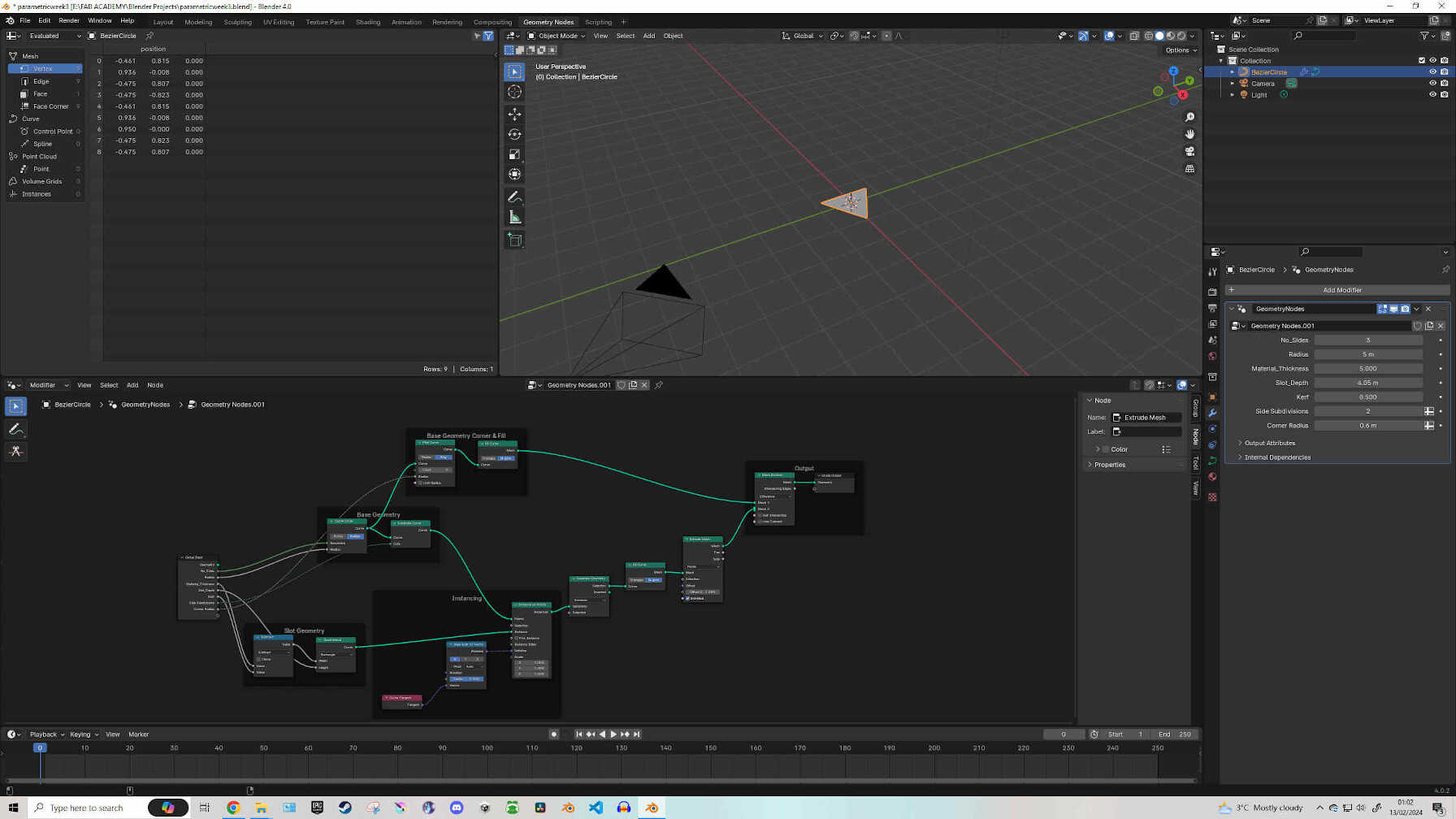
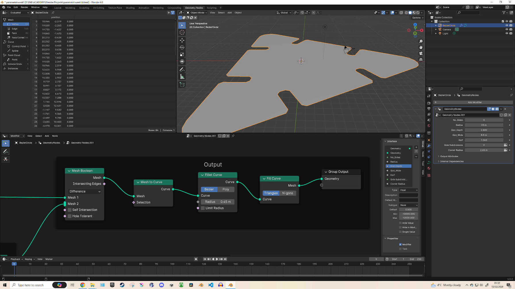
We have a few more nodes to add and connect before finishing the tutorial. Add ‘Separate Geometry, Fill Curve & Extrude Mesh’ nodes, then make the appropriate connections and toggle the Fill Curve to ‘N-gons’. Now add two ‘Math’ nodes and an ‘Index’ node. Set one Math node to ‘Add’ and the other to ‘Floored Modulo’. Make your connections and input the number ‘1’ into the bottom Value cell of the Add node.
At this point in the tutorial, the writer says he made a mistake - though by following his correction, the order will be wrong. (Slot Depth & Slot Width labels should be swapped, then it’s all good).
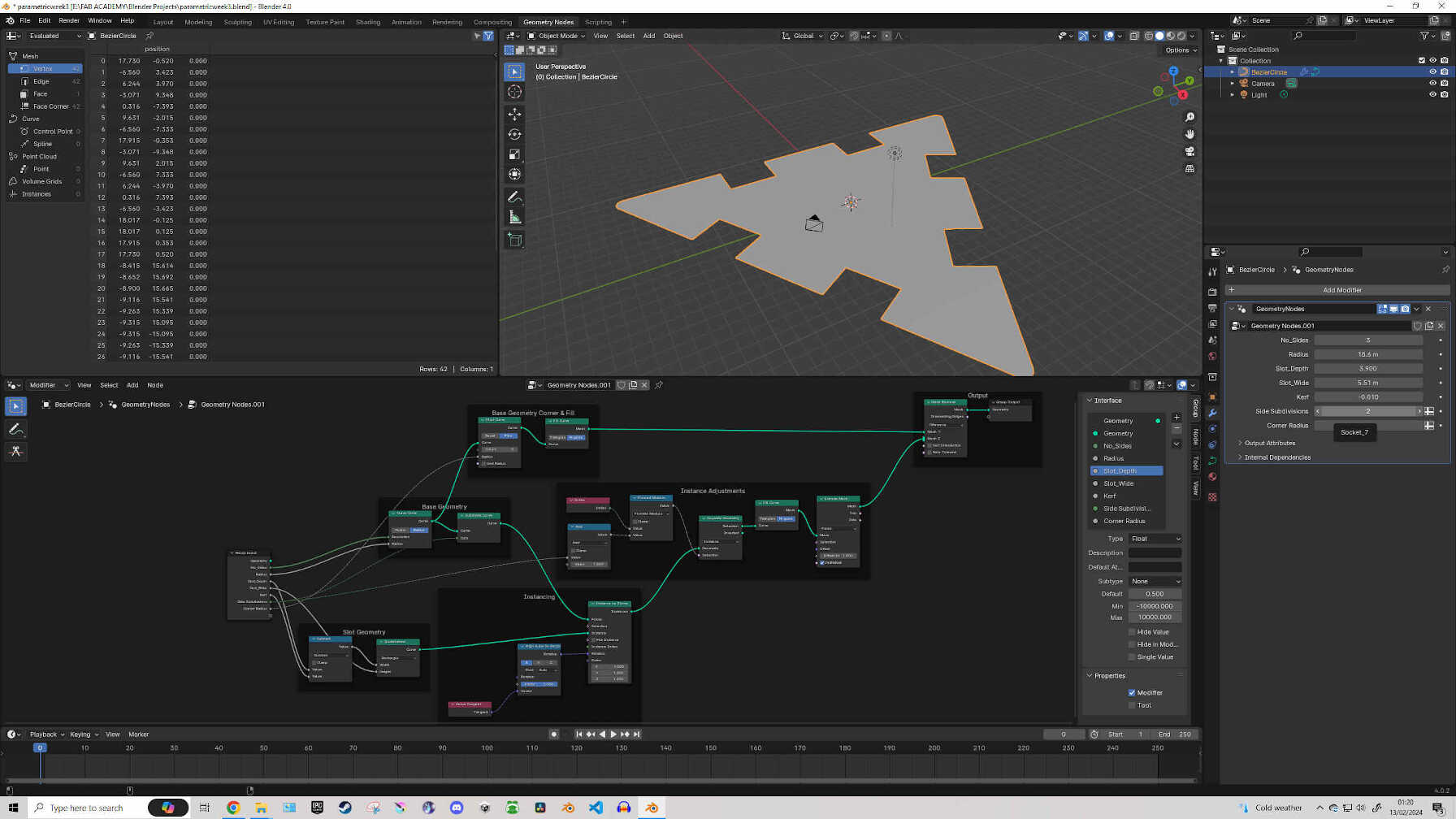
For the final part of the tutorial, add the nodes ‘Mesh to Curve, Fillet Curve and Fill Curve’ and make the connections. In this case, I didn’t need to make connections as dropping the nodes into their correct positions will make the connections for you. Congrats dear reader, you have reached the end of the node design tutorial! Now onto bringing the design into the laser cutter!
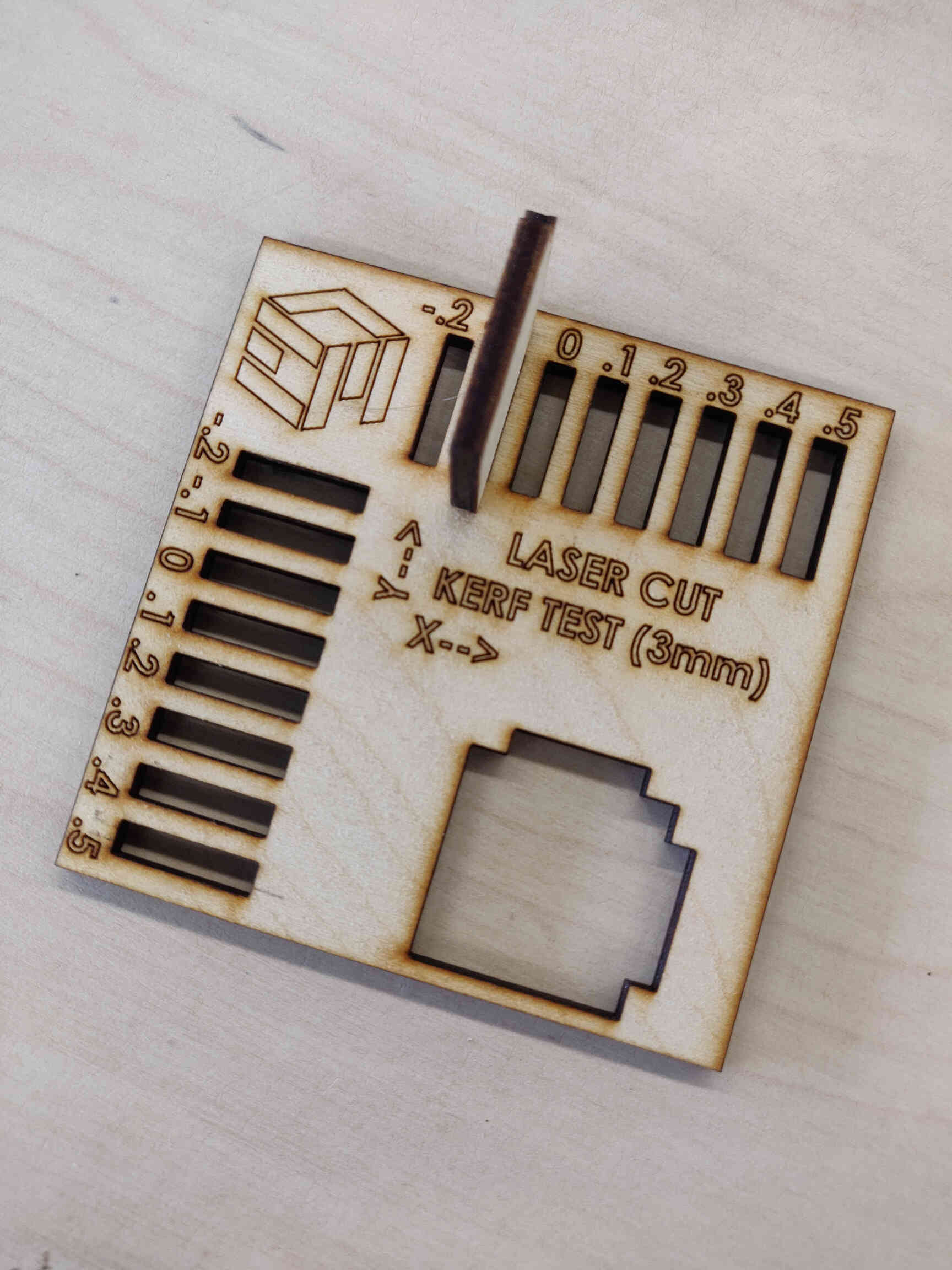
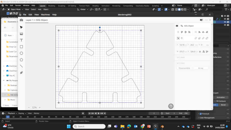
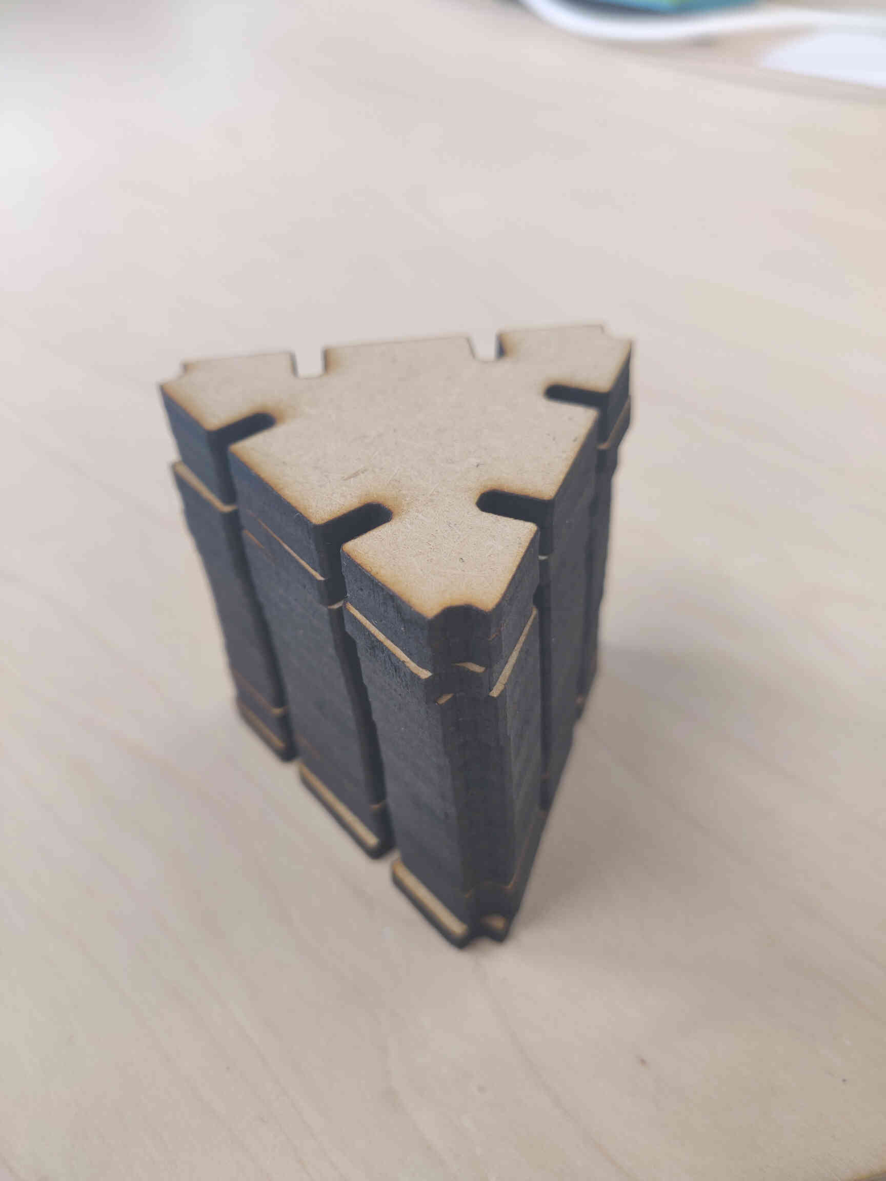
Once I finished the tutorial, I messed around with the settings & measurements to personalize the Parametric Design. I had the tools set up to manipulate the radius, slot depth, slot width, kerf and number of sides / slots. I rounded the corners but left enough room for a notch on all 3 corners, with the intention that it could be used for stabilizing structures. Slots were designed to be 3mm in width as that is the thickness of the wood material that I would be laser cutting.
Export issue & Fix
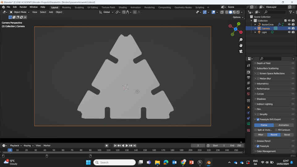
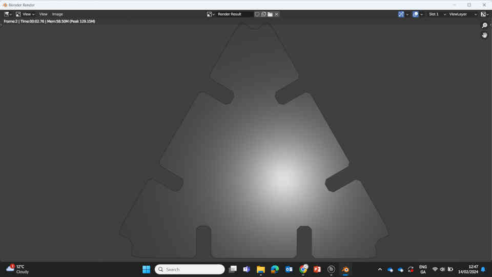
I ran into a bit of trouble exporting the image into a Vector SVG, as the 'Grease Pencil SVG' method wasn't being recognized by the laser cutting software “Beam Studio”. A quick Google search later, I discovered there is a Blender Plugin that was built into Blender called “Freestyle SVG”. I just had to turn it on and adjust the settings. It uses the Camera in Blender to view the object and draw/render a 2D vector outline around the object and export it as a recognizable SVG. I just had to position the camera *directly* on top of the model, looking straight down. If the camera position or setting weren’t correct then it would mess up the parametric measurements after rendering.
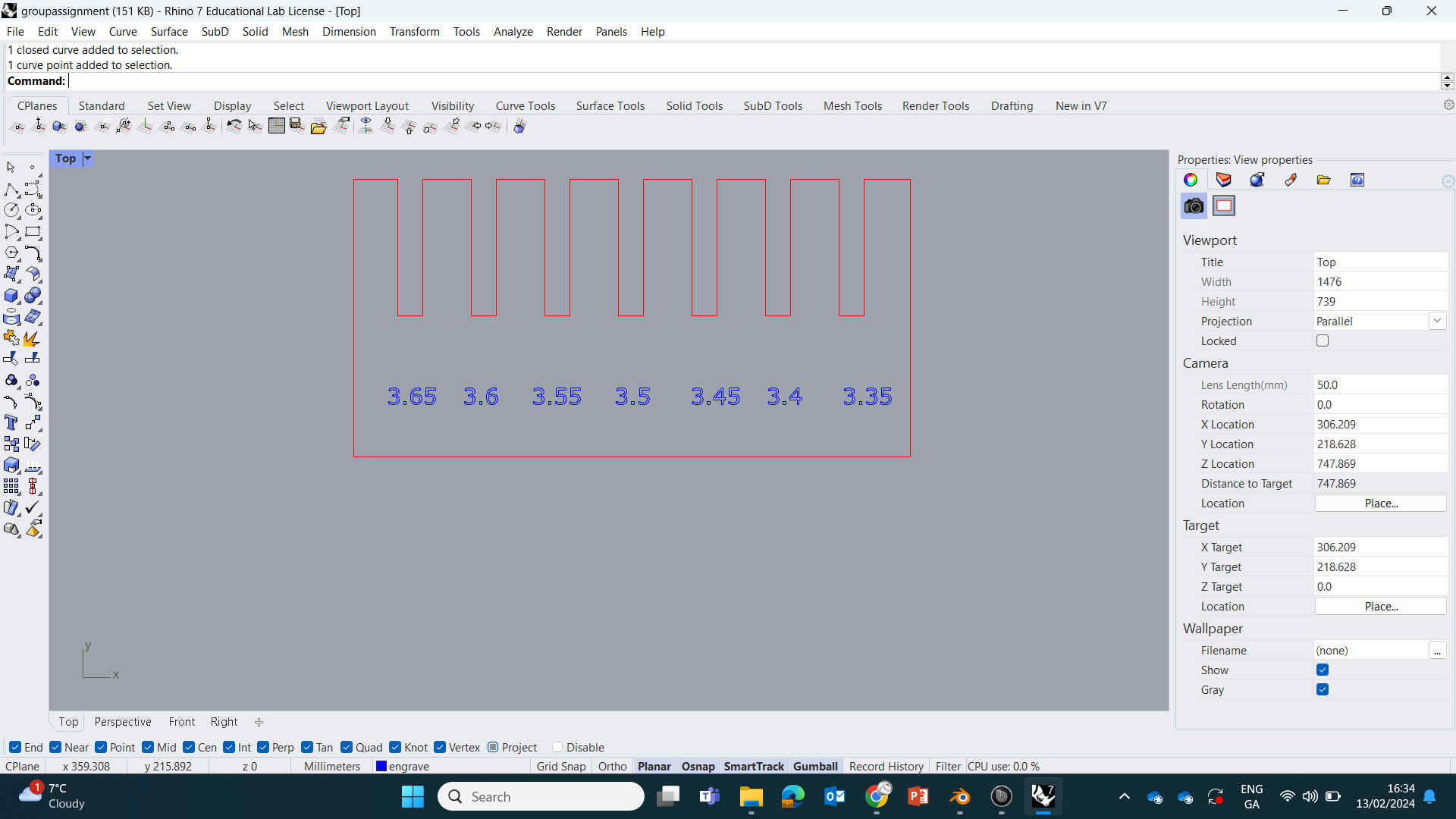
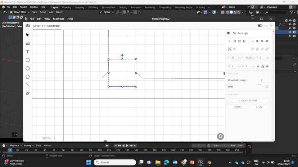
Once exported, I brought the SVG file into Beam Studio. The next issue needing to be addressed were the measurements. The parametric design was set to have a 3mm slot width relative to itself, but when brought into Beam Studio, the scale of the image was too big and would have to scale it down to where the slot size would be EXACTLY 3mm in the physical world.
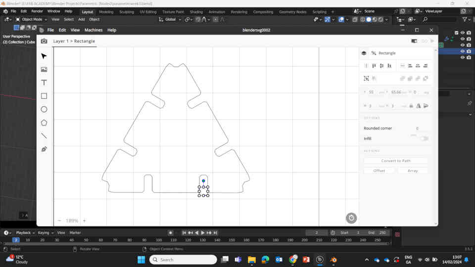
Very simple and easy fix to this: I created a square box in Beam Studio that was exactly 3mm x 3mm in size and positioned it between one of the slots, then scaled the SVG file down so that the 3mm box would fit snugly into the 3mm slot. Then duplicated the design multiple times to produce roughly 10 of them. (Spoilers: it worked like a charm once laser cut!)
Laser Cutting Parametric Design
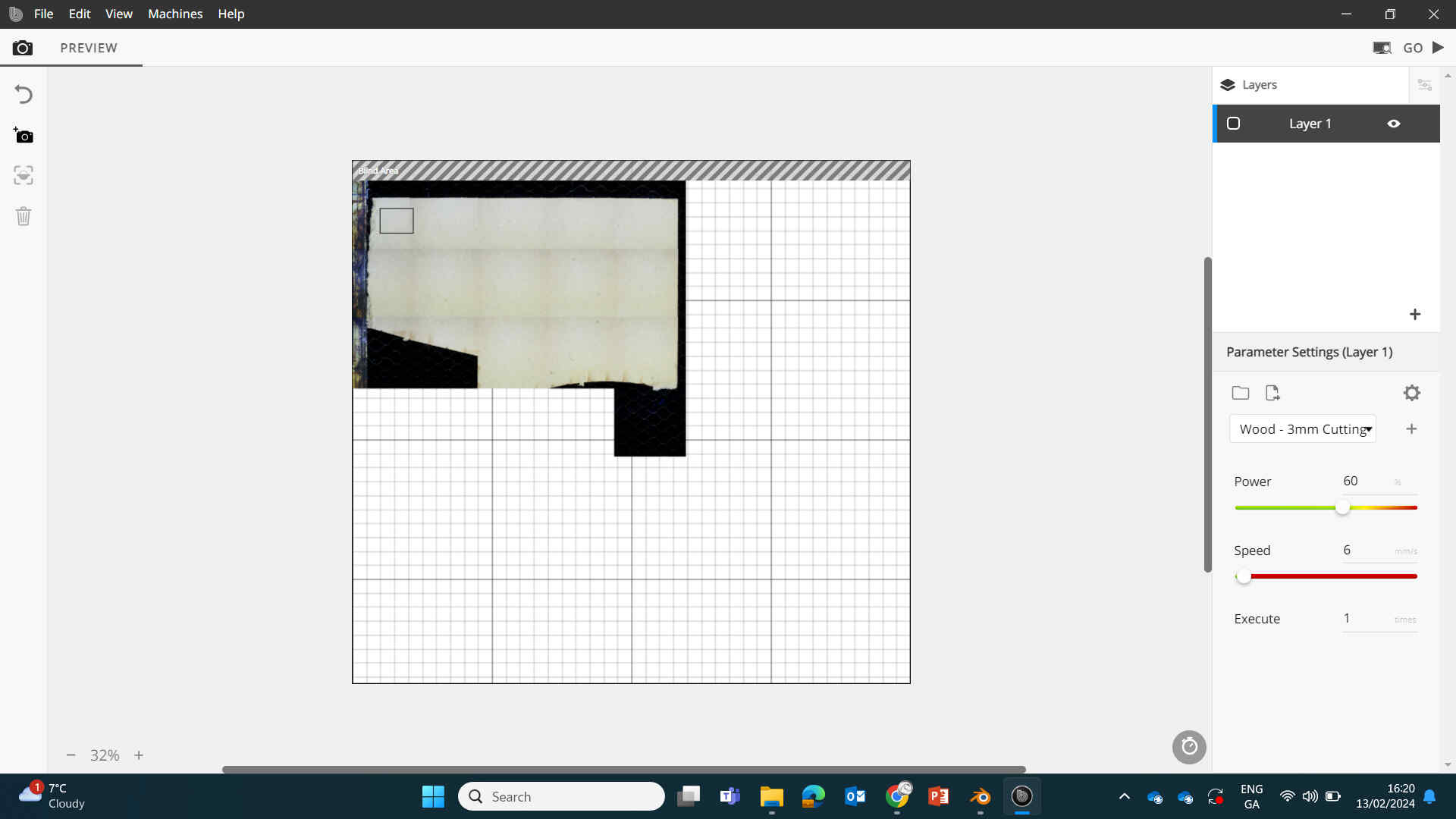
Once that was done, I began preping the laser cutting process. Placing 3mm MDF boards inside the laser cutting machine, turning on the machine & the Fume Extractor.
(Didn't help with the smell though).
After taking all safety precautions, I measured the correct distance between the laser & the board. Then I connected my laptop to the machine via Wifi and clicked the Camera icon on the top-left corner, then dragging across the workspace to view the camera inside of the machine. This allowed the machine to use its camera to scan the inside and show me a clear representation of the space & MDF placements inside.
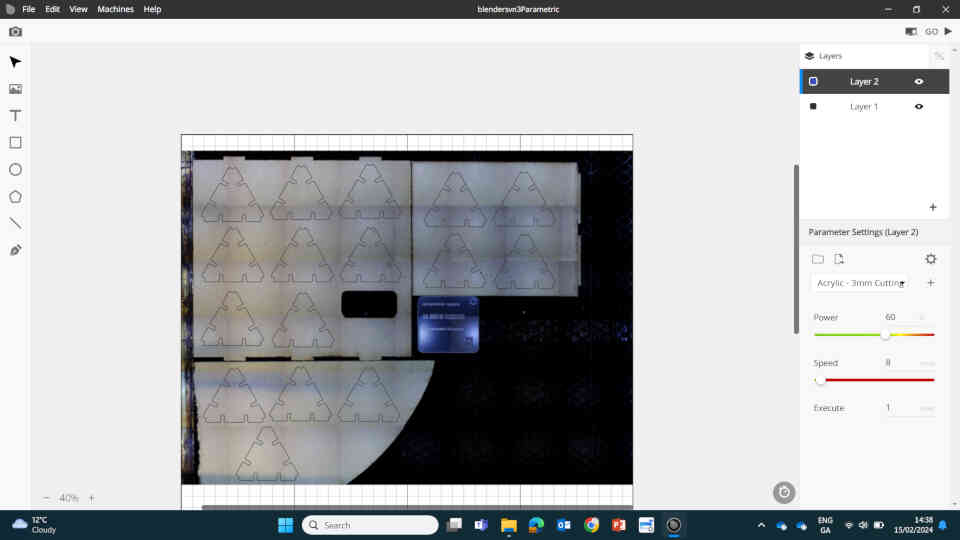
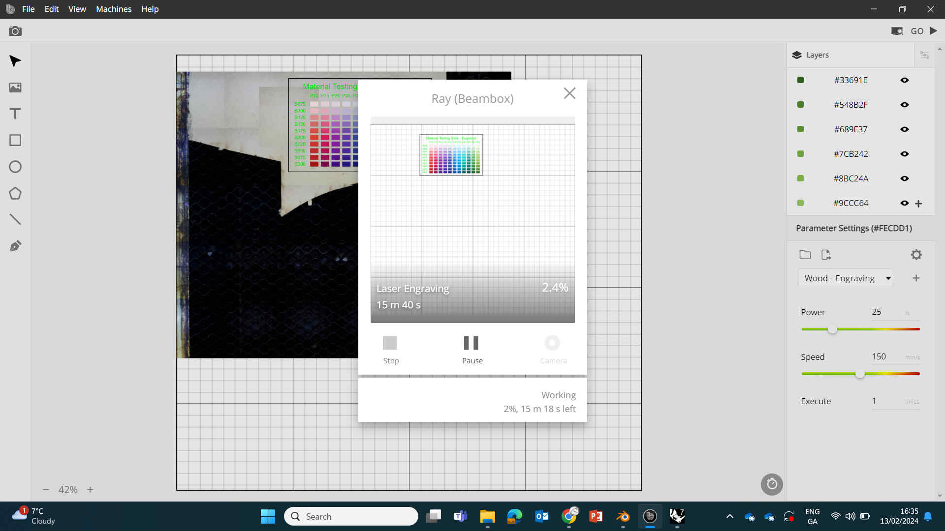
Once I positioned the MDF and Vector designs where I wanted them, I hit ‘GO’ and it began cutting. Oscar also guided me through 'Nesting' options for my next cutting assignment.
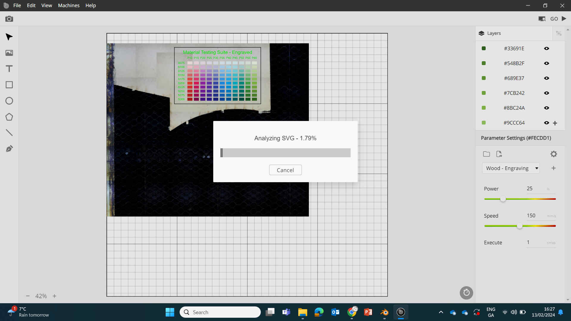
I also used the same method above to perform the Cutting & Engraving example tests and for the press fitting group assignment - (These can be viewed at the end of this page).
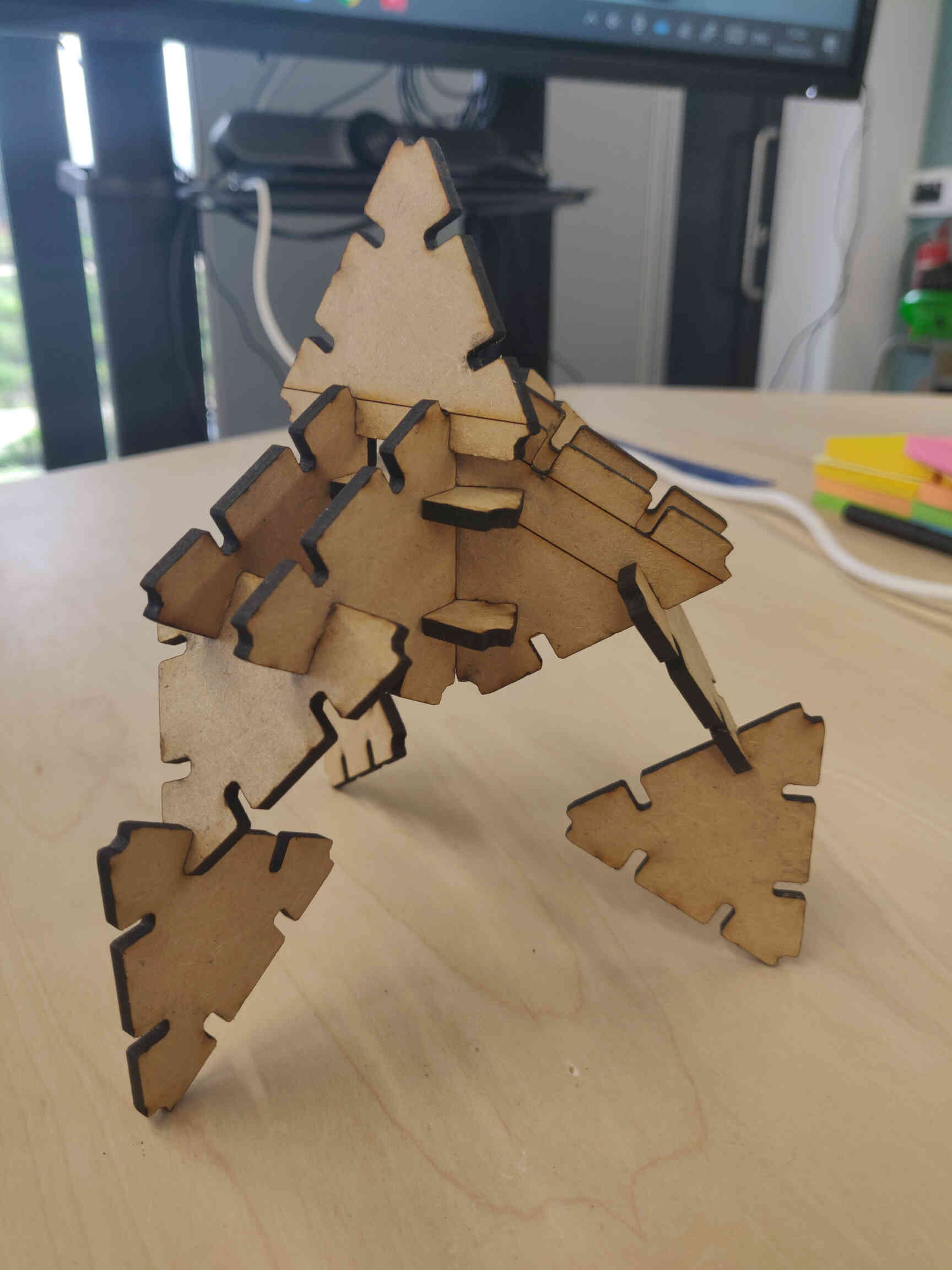
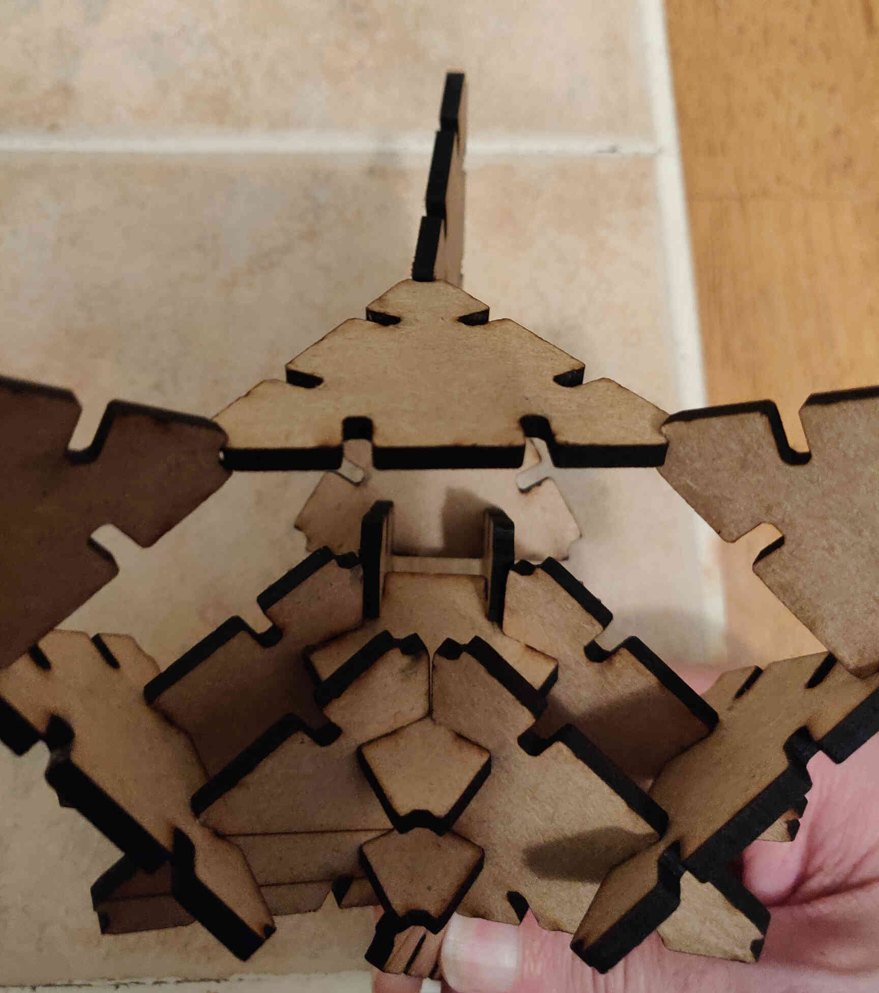
Once complete, I spent the next hour just messing around with my parametric cuts building rockets, ships, dogs and robots. Not quite sure yet how I could implement laser cutting into my final project, but its a great skill to have that has a lot of potential - especially for marketing.
____________
Inkscape & Vinyl Cutting
To start the Vinyl Cutting assignment, I wanted to design a logo for my final project as if it was being sold as a commercial brand. I chose Inkscape as my vector software of choice.
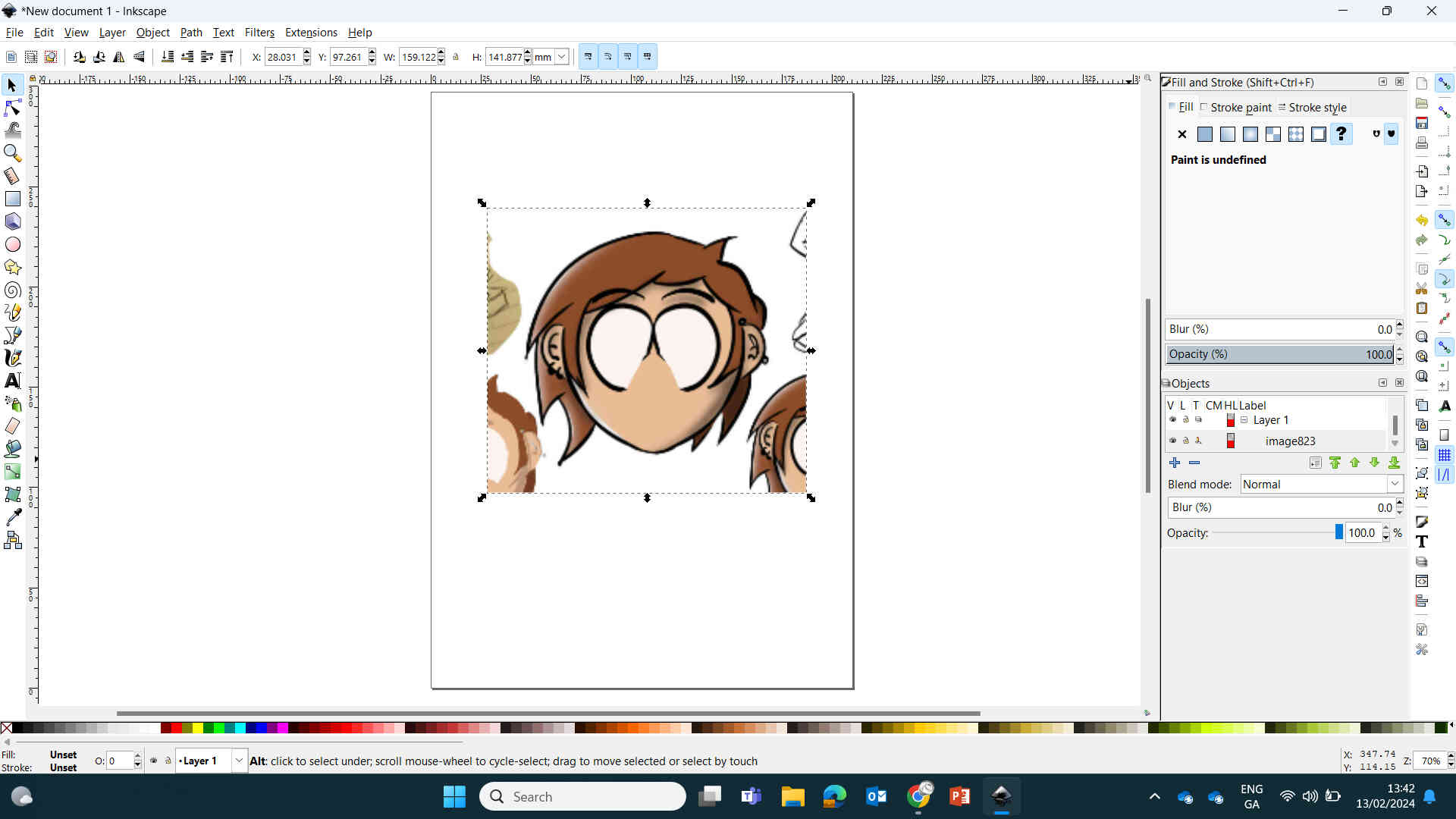
I was pretty happy with the ‘Little Buddy’ concept designs I made in Procreate, and decided I would use the head of the product as the logo. I opened up Inkscape and imported a cropped image of the head illustration into a new layer and set the opacity to 20%.
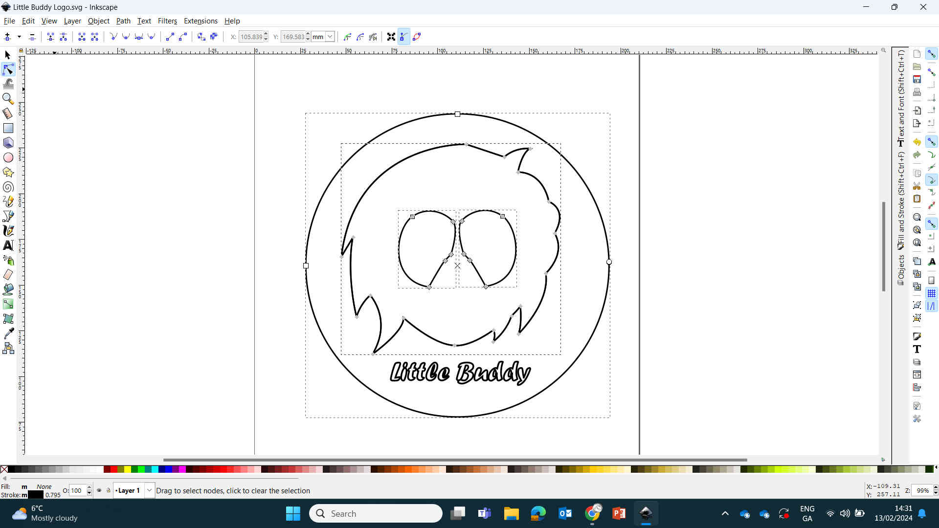
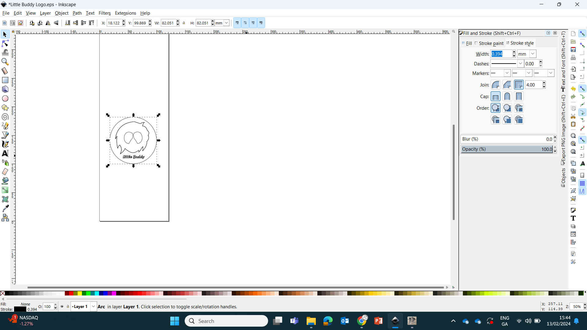
On a new layer I traced an outline over the head, hair and eyes using the ‘Draw Bezier Curves’ (pen) tool and ‘Edit Paths by Nodes’ tool. Any lines that were separated, I just selected all and ‘Joined’ them.
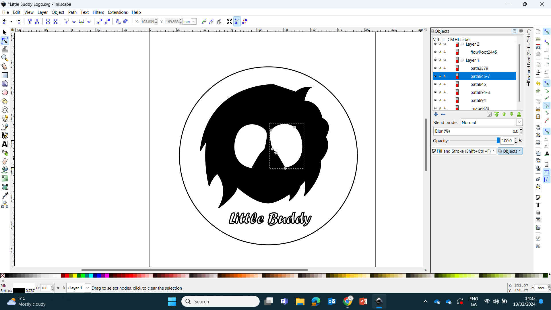
I filled the head/hair with black and the eyes with white to see the image I was going for. Make sure the eyes are on a layer above the head layer.
Once I was satisfied with the design, I reverted the Fills and set the vector lines to ‘Hairline’ size and exported it as a PDF, PNG & SVG - just to be safe.
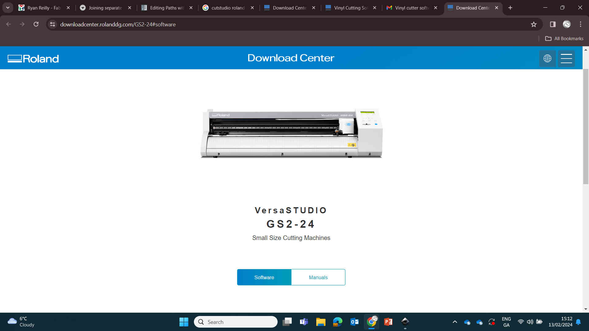
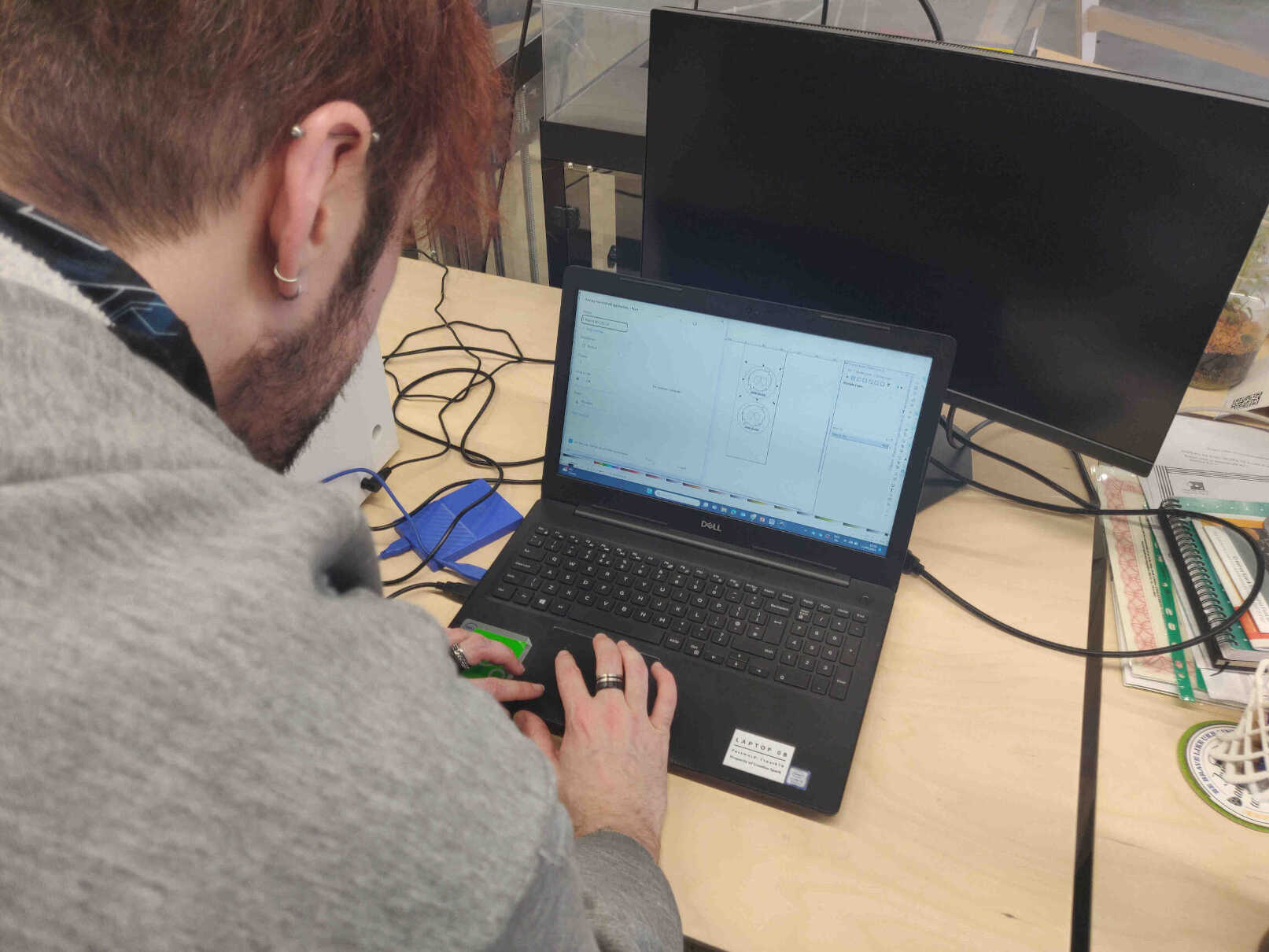
I tried importing the design into "Cutting Floor" software but didn't properly recognize my design when imported. Carl, the FabLab technician, highly recommended sending the design to the Roland cutting device directly from Inkscape itself using a plugin. Though when I look back on my notes, I'm not entirely sure if we even needed a plugin. I believe that inkscape was able to send it over directly on it's own - didn't even need the exported files.
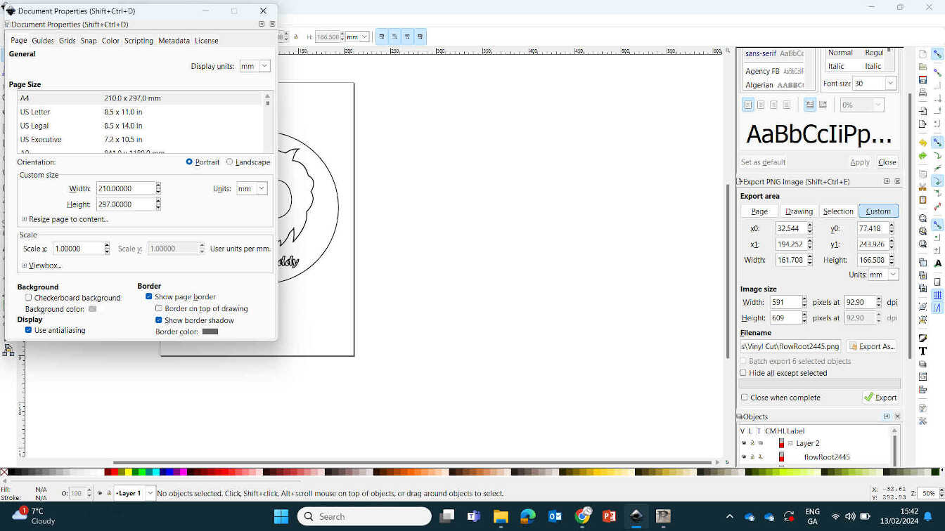
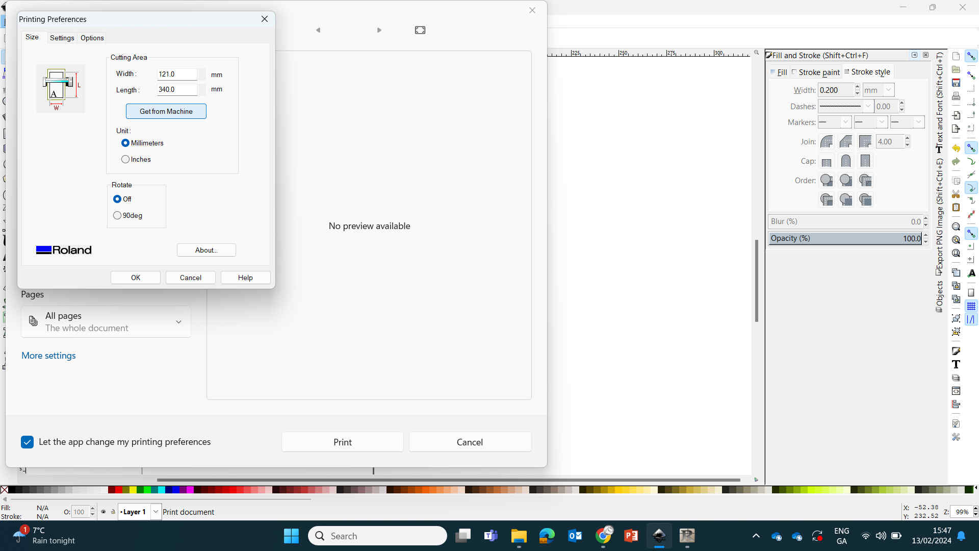
I then went into the Inkscape Canvas settings and set the canvas dimensions to exactly what the Roland machine measured. But that isn’t enough - I also needed to go into Print Settings and set the exact measurements there. However, as the cutting machine was already hooked up and measured the dimensions, all I had to do was hit “Get from Machine” and the Roland cutter set them for me.
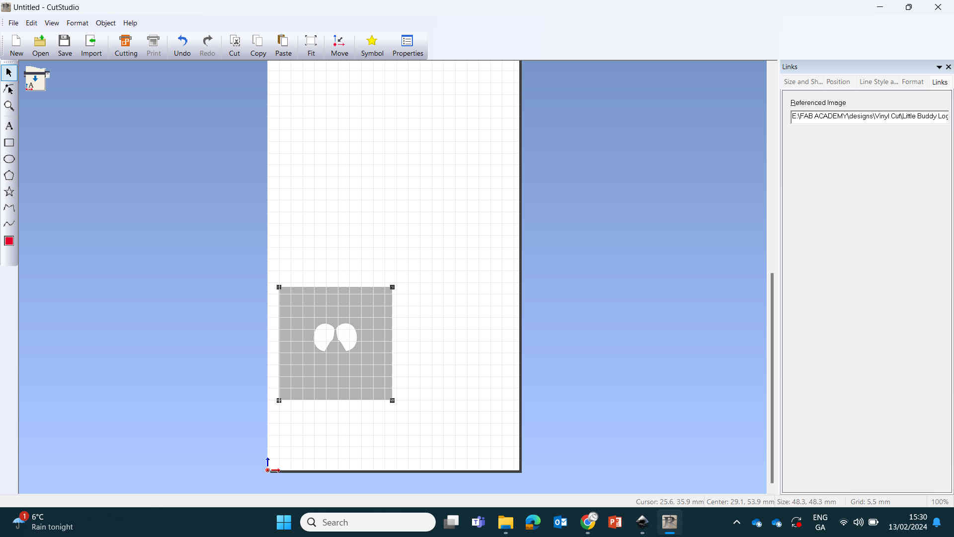
I placed the sheet of blue vinyl into the Roland machine and it calculated the Height & Width measurements of the vinyl sheet. For a quick test for knife height, we got it to cut out a square that was placed onto the canvas.
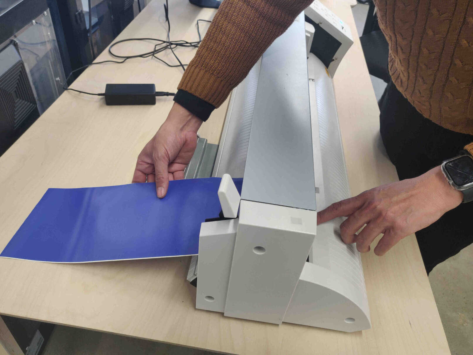
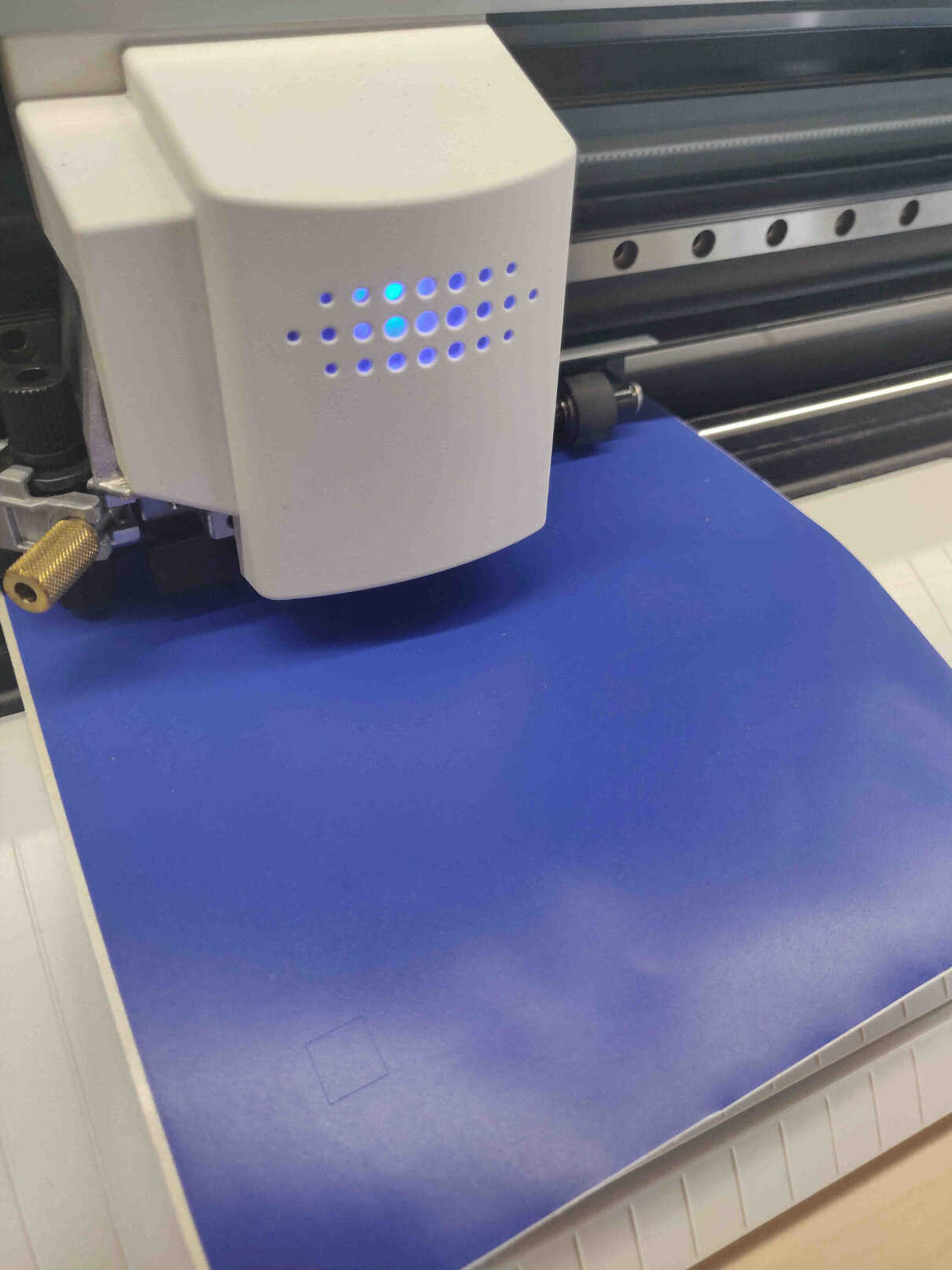
With everything set, the machine cut 2 versions of the same logo, and I peeled off the vinyl as I intended, then peeled off the 2nd logo in reverse.
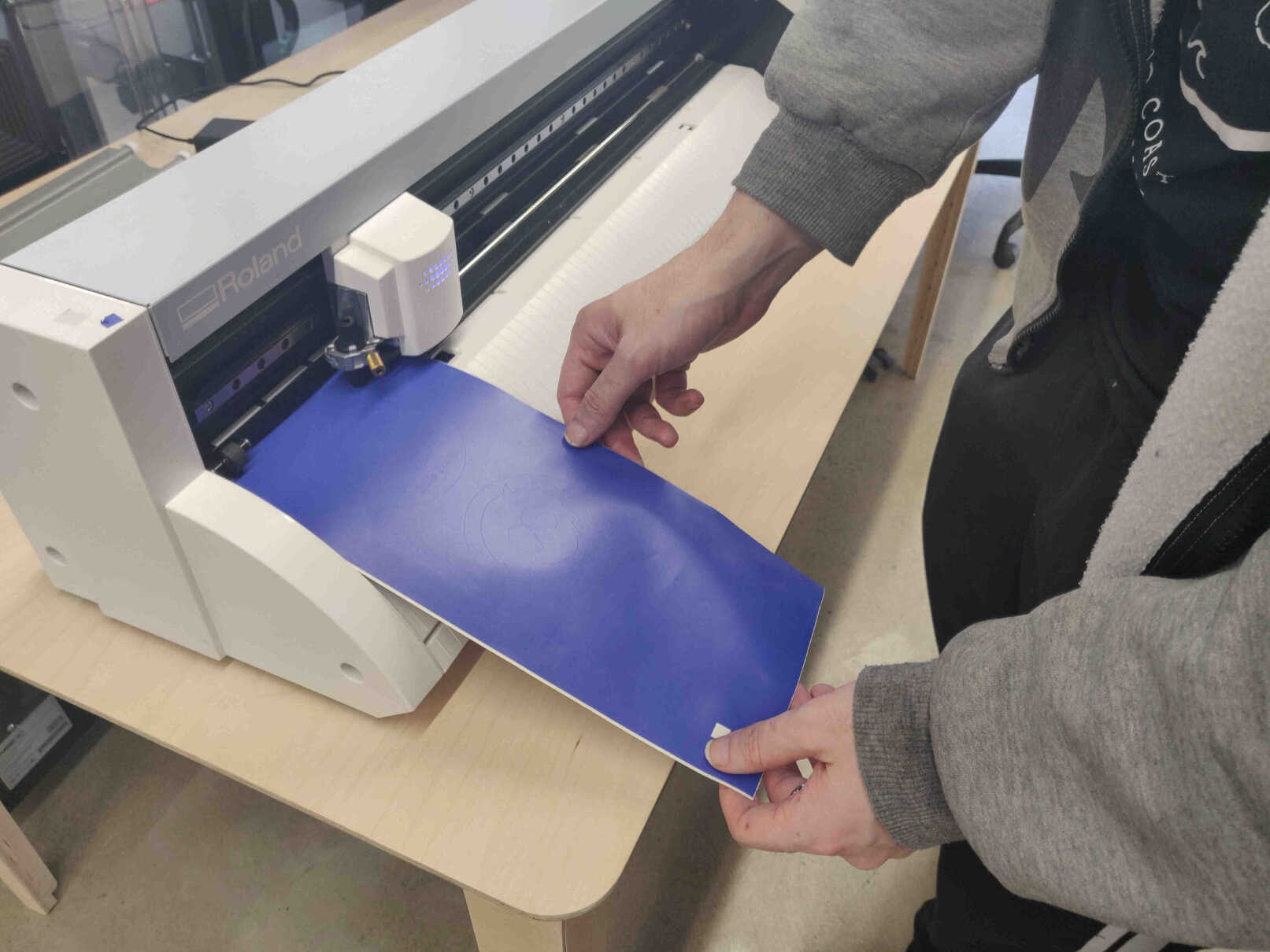
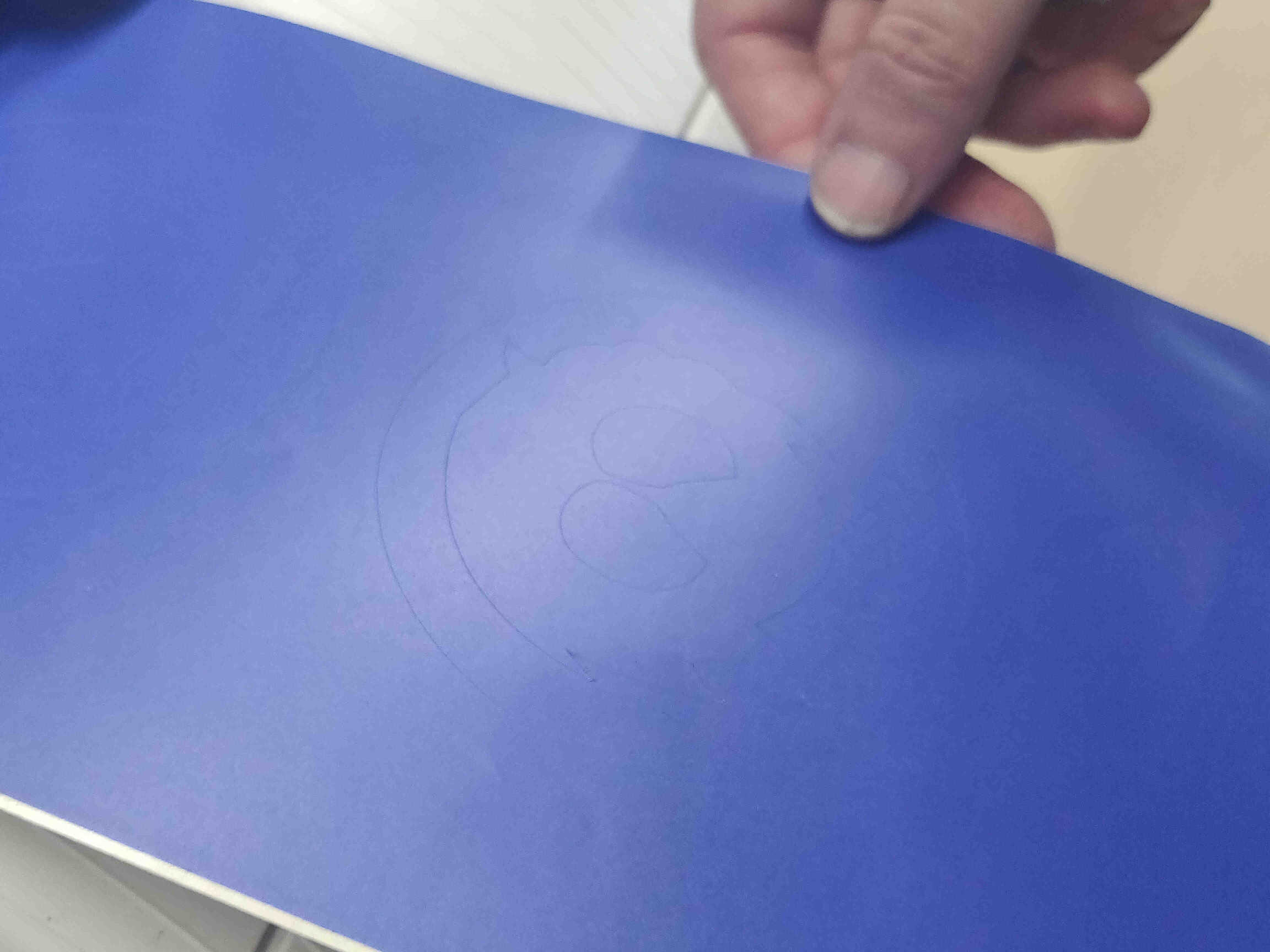
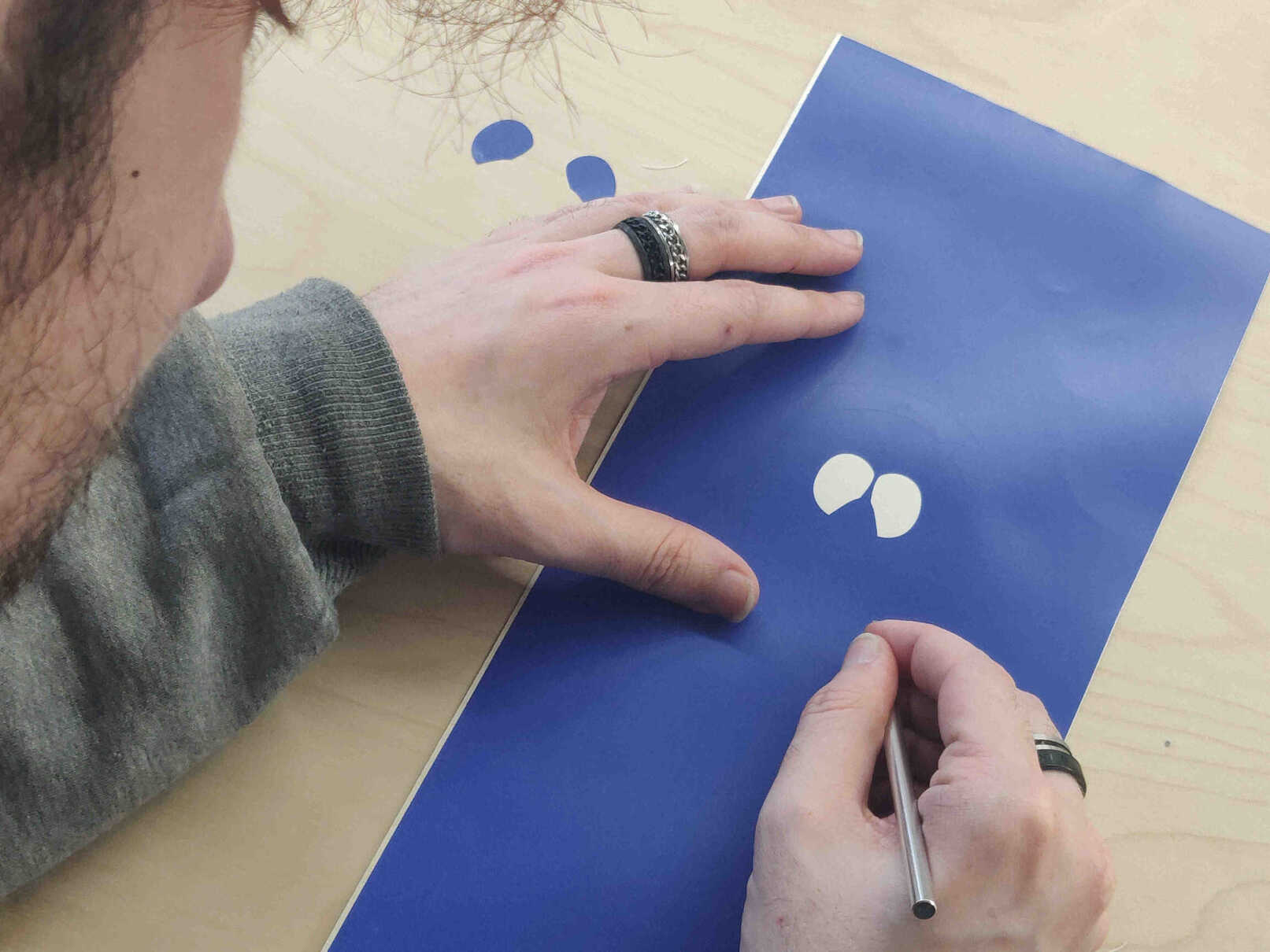
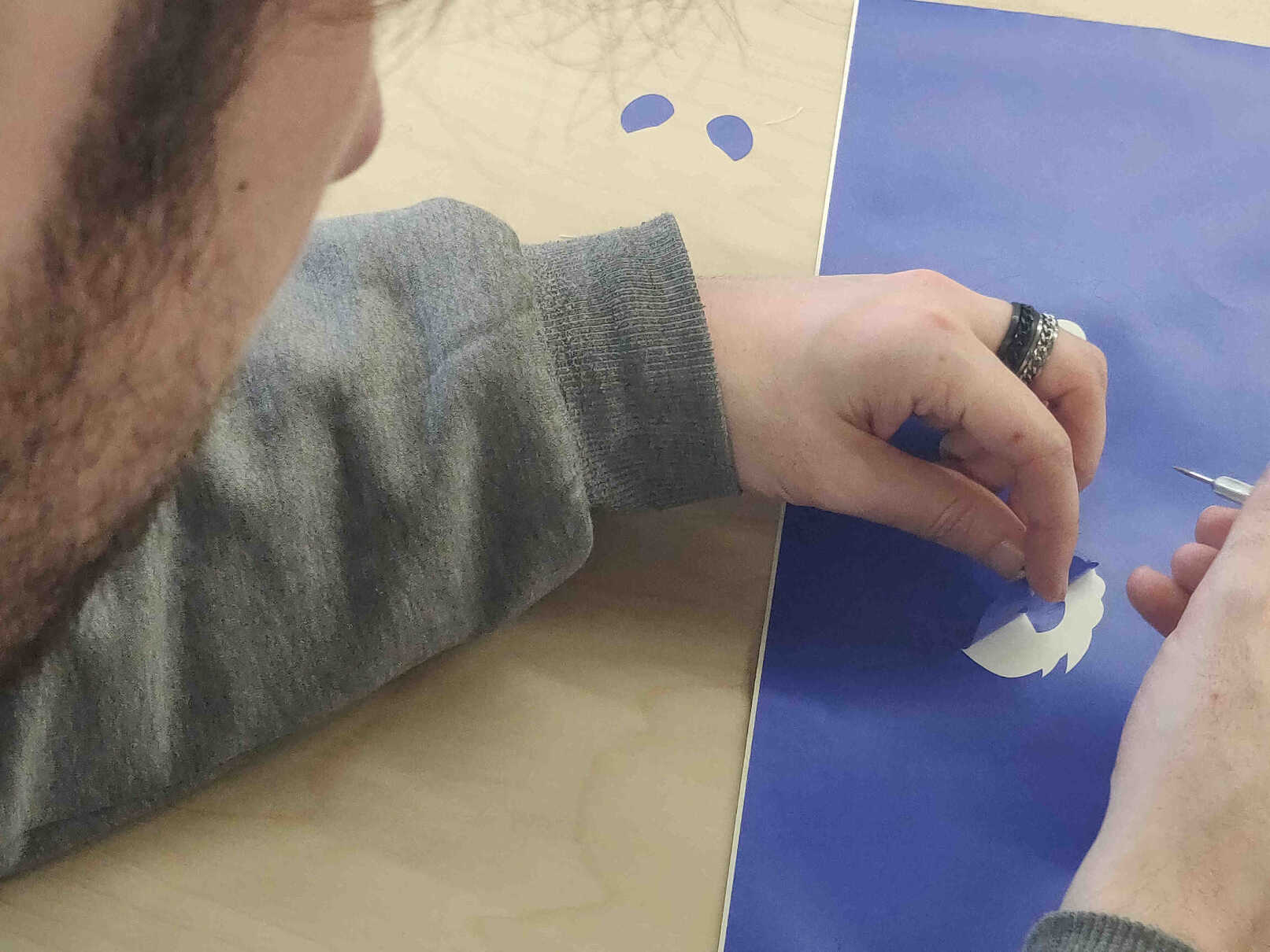
I was very surprised just how quickly the vinyl cutter completed slicing the design. It was pretty much finished by the time I looked at the machine from my laptop, and it came out perfectly. Such a simple and effective way to make stickers, I definitely want to use the Vinyl Cutter in the future for my own personal projects!

____________
Conclusion/Reflection
Computer Controlled Cutting was a week I was very interested in as I have some experience in the fablab using this process and was interested in learning more about it as it’s a great opportunity to create merchandise for my YouTube audience. Previous experience included Waterjet cutting and Laser cutting.
Though this week emphasizes parametric design, and I get a bit nervous when it comes to measurements, so I was curious how it would go. The brief run through Grasshopper with Oscar was very helpful in understanding the node design process. Our recitation in AI tools for CAD was very interesting as it shows the potential for AI to take up a lot of the menial work - or replace us entirely. Parametric Press Fit was concerning as I didn’t understand it at first but was guided through how it’s relevant to my final project.
Using Blender Geometry Nodes was a great experience and something I really enjoyed working on as it reminded me of designing microchips for levels in LittleBigPlanet (PS3) or doing colour correction in Davinci Resolve. However I wouldn’t have the knowledge to innovate or design the nodes from scratch with my own ideas. There was an issue, as previously documented, that my design wouldn’t take shape. But I had the right idea in continuing on as I knew the shape would eventually come together once I solved the issue. The result when laser cut was better than I expected. The potential for creating crazy cardboard designs is very much within reach.
Using Inkscape for Vinyl Cutting was an eye-opening experience as I couldn’t believe how easy the process was to make Vinyl stickers. This is certainly an option for me in the future in case I need to make any merchandise or make my game consoles have cool designs.
Helpful Nueval QA + Cheatsheet
____________