Group Assisnment Week 12 - Input Deivces
In this week, I am going to:
- Probe an input device(s)'s analog levels and digital signals
- Document my work on the group work page and reflect on my individual page what you learned
Research: How Input Devices Works with Microcontroller
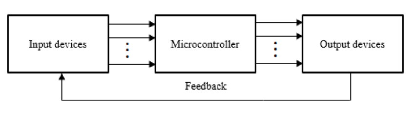
Input devices play a crucial role in interacting with microcontrollers. These devices convert physical actions or environmental conditions into electrical signals that the microcontroller can understand and process.
For example, a push button acts as a simple input device. When pressed, it closes a circuit, generating a logic high or low signal that the microcontroller's input pin detects. Sensors like temperature sensors, light sensors, or accelerometers measure specific parameters and send corresponding analog or digital values to the microcontroller.
The microcontroller continuously monitors its input pins for changes in voltage or digital states. It uses programmed instructions to interpret these signals and take appropriate actions based on the received input.
In some cases, input devices may use communication protocols such as I2C or SPI to send data to the microcontroller. The microcontroller then follows the protocol's rules to receive and decode the information.
Overall, the seamless integration of input devices with a microcontroller enables the creation of systems that respond intelligently to the surrounding environment or user interactions.
Research: List of Ports and Input Sensors
Ports
Digital Ports
- Description: Individual pins that can be configured as input or output.
- Functionality: Handles binary values (0 or 1).
Analog Ports
- Description: Pins capable of receiving analog voltage levels directly.
Comparator
- Function: Compares two input voltages and provides a digital output indicating which is higher or if they are equal.
A/D (Analog-to-Digital Converter)
- Function: Converts analog input voltages into digital values for processing by the microcontroller.
I2C Method
- Description: Inter-Integrated Circuit, a serial communication protocol.
- Details: Uses two wires (SDA for data and SCL for clock) to connect multiple devices to the microcontroller. Devices like sensors use I2C to send data to the microcontroller.
Input Sensors and Details
Temperature Sensor
- Use: Climate control, industrial processes, electronic device monitoring.
- Output: Voltage or digital signal proportional to temperature.
Light Sensor
- Use: Automatic lighting systems, camera exposure adjustment, solar applications.
- Output: Lux values or percentage of maximum light intensity.
Pressure Sensor
- Use: Automotive systems, industrial pressure control, medical devices.
- Output: Data in units such as pascals or psi.
Accelerometer
- Use: Mobile devices for orientation, gaming, vehicle safety systems.
- Output: Values in units of g (gravitational acceleration).
Gyroscope
- Use: Navigation systems, drones, virtual reality devices.
- Output: Rotational velocity or angular rate in degrees per second or radians per second.
Proximity Sensor
- Use: Smartphones for screen functionalities and automatic call handling.
- Output: Binary signal indicating proximity.
Humidity Sensor
- Use: Weather stations, agricultural applications, indoor climate control.
- Output: Humidity values as a percentage.
Magnetometer
- Use: Compasses, navigation systems, industrial applications.
- Output: Magnetic field strength and direction data.
Information about Oscilloscope and Signal Generator
We have one Dual Channel Function Signal Generator in the lab:
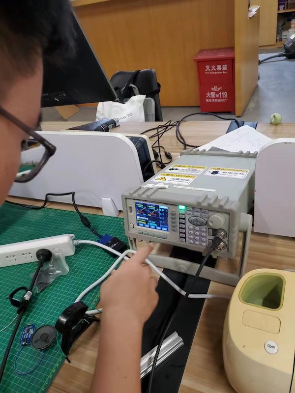
This device can generate 40mHz ~ 25MHz signal, with 100MSa/s.
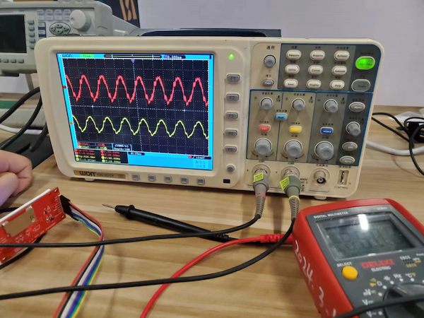
And this is the Oscilloscope we are using and the function seems ok:
Sense the signal from DHT11 sensor��
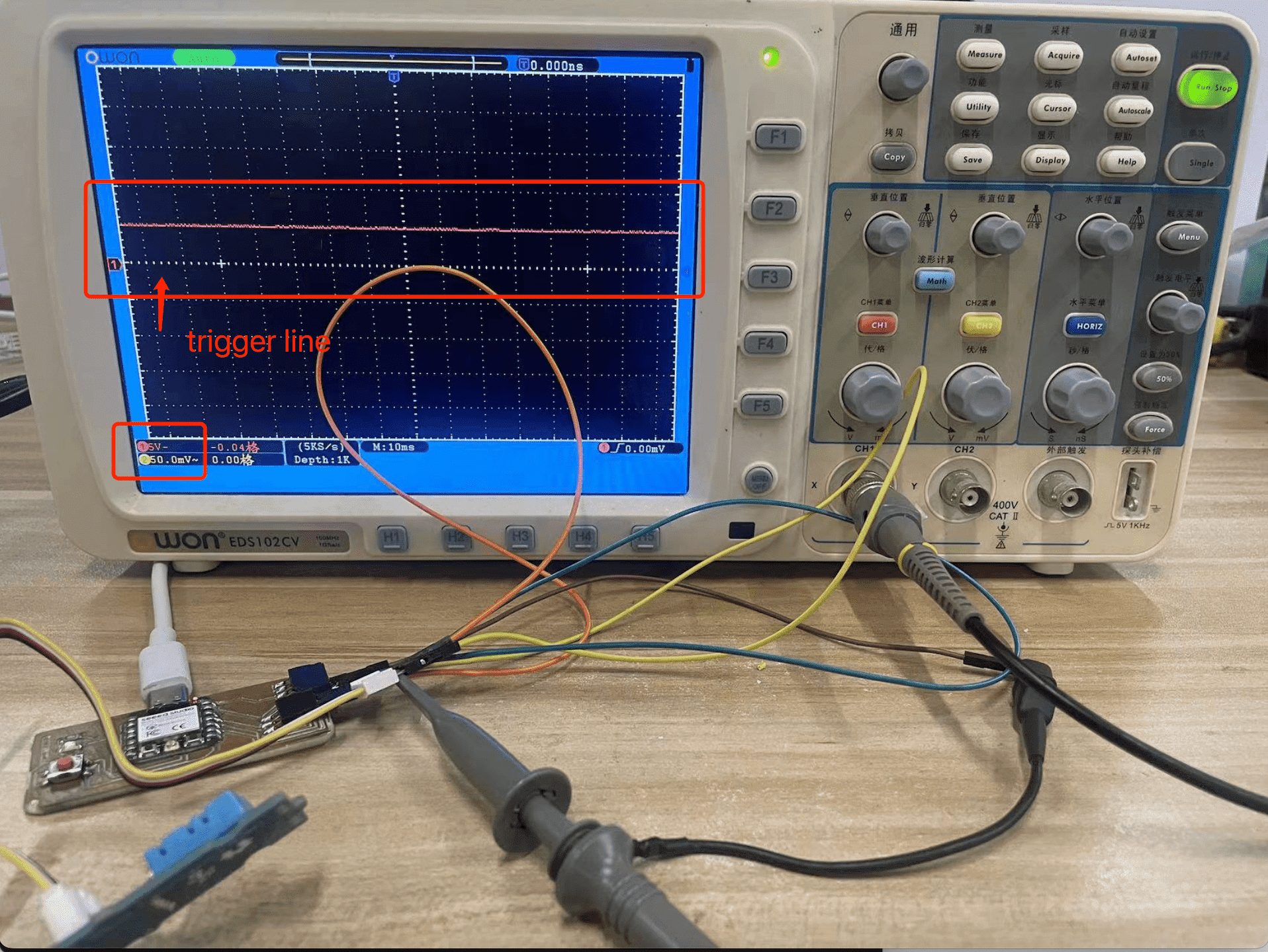
Connect the probe to the Oscilloscope. Press the trigger level button on the panel, and then press CH1 to adjust the trigger level.
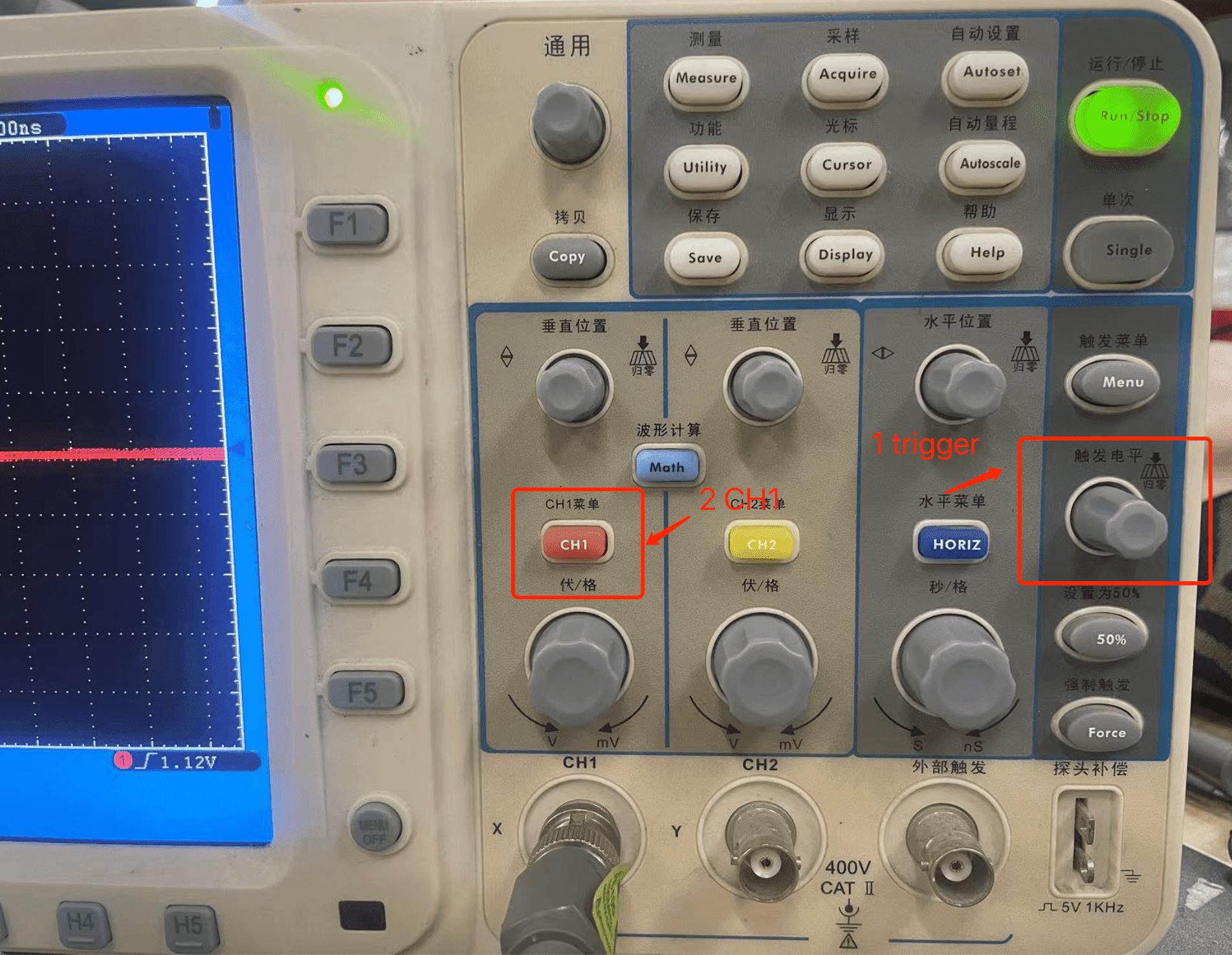
Adjust the coupling mode to direct current

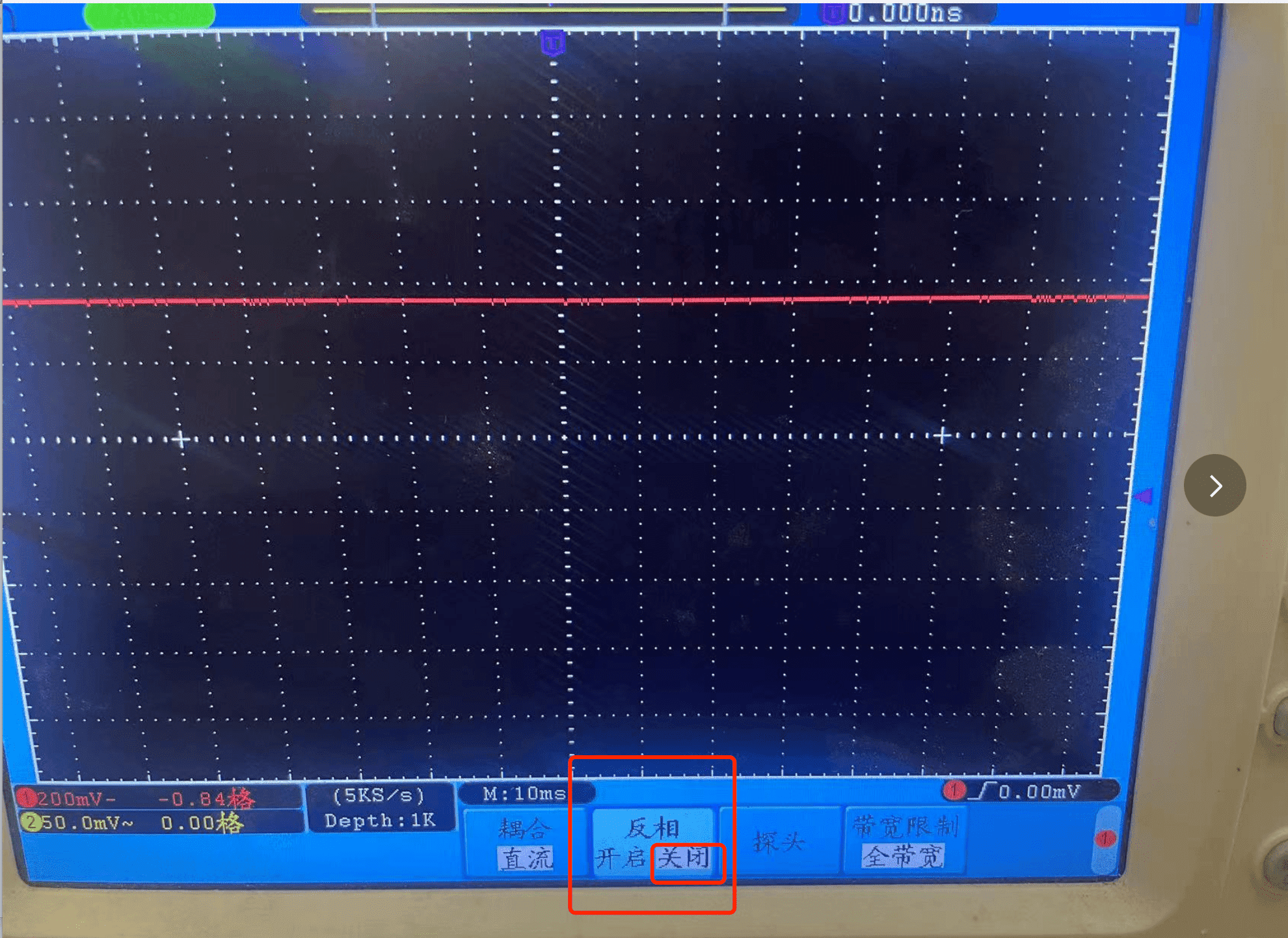
Reverse the adjustment to off
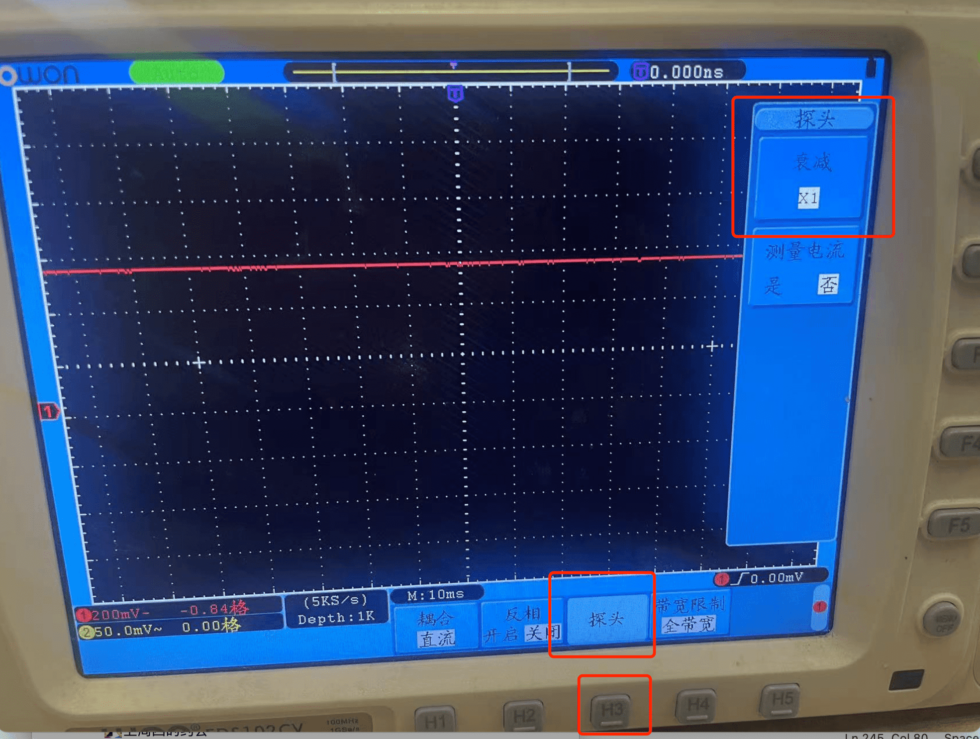
Adjust the probe magnification to X1
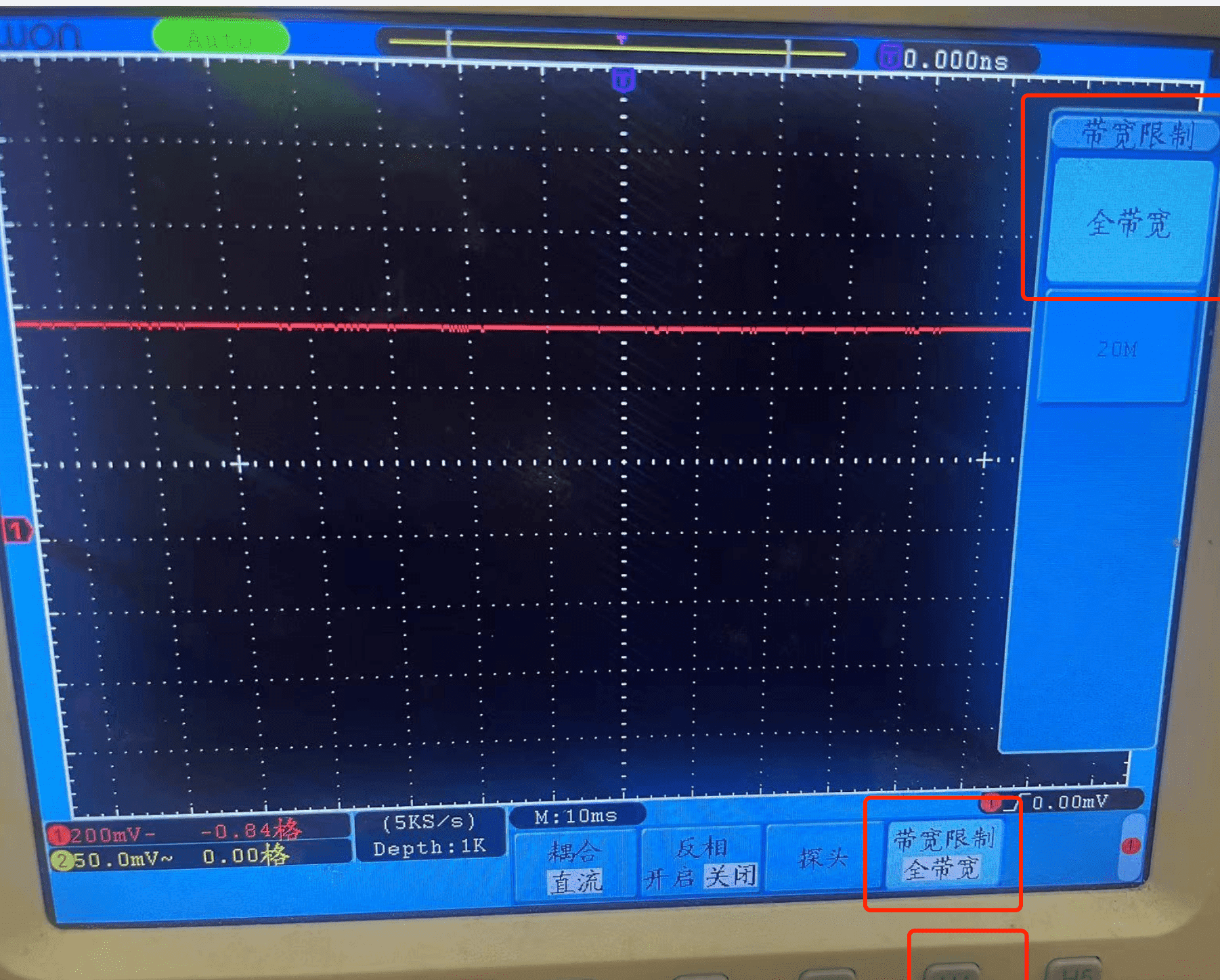
The bandwidth is set to the full bandwidth
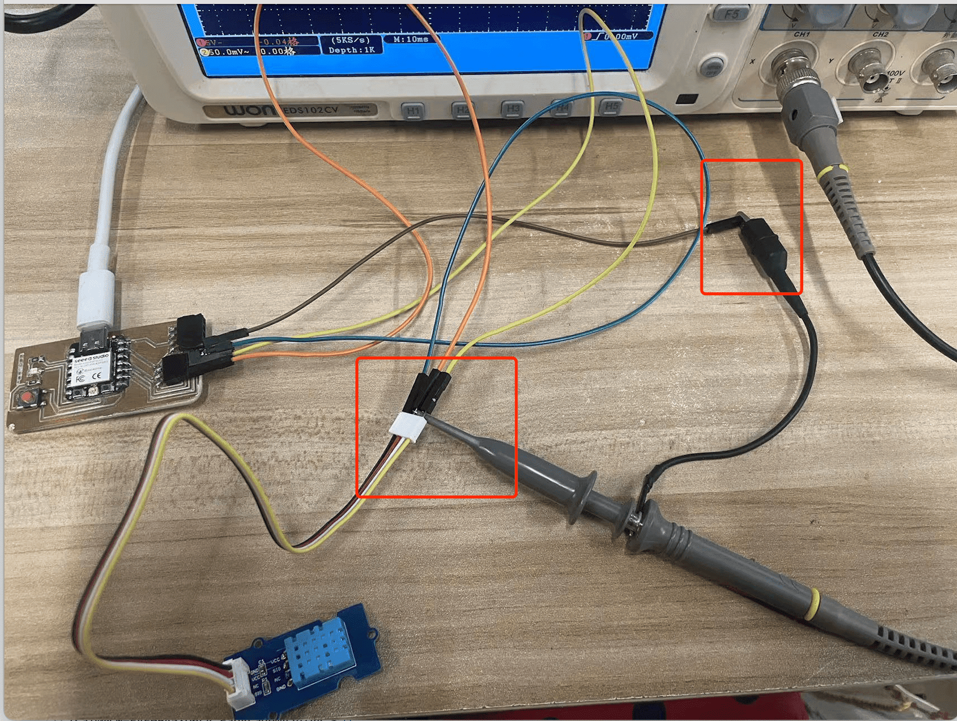
Clamp the ground wire to the ground wire of the ESP32C3. Hook the signal wire to the VCC wire of the DHT11.
The votage signal is okay!Because one grid is 5V and the voltage line is at one grid position above the level line, the voltage is a constant 5V.
Now using DHT11 sensor to check the signal and applying channel 1. Here is the connection:
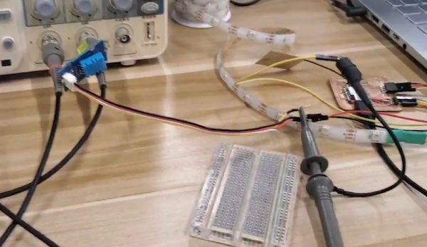
Then after connecting the both sides for sensing. We got the results:
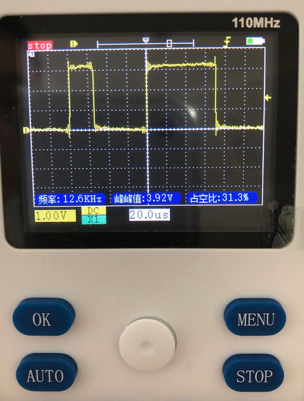
Every time I need to make sure that the grounding wire of the measuring probe (usually the black wire or grounding clip on the oscilloscope probe) is properly grounded when making an oscilloscope measurement. This is to avoid signal interference or electrical noise, but also to be on the safe side. Proper grounding can help obtain a clearer and more accurate signal waveform.
Then this should be the actual signal output:
Using another
We are using another one for the sensing of DHT11 sensor:
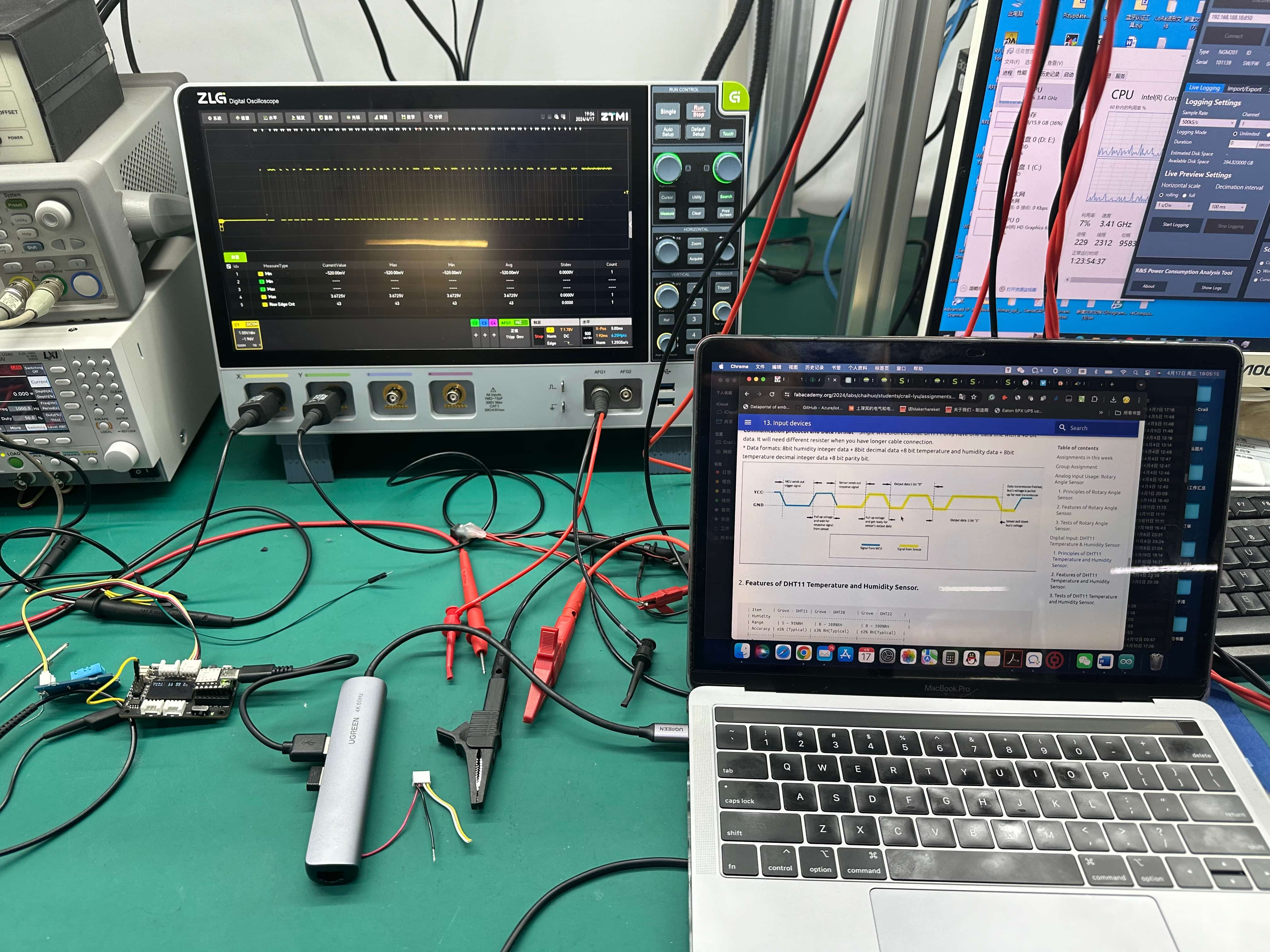
The is ZLG Digital Oscilloscope. And we connect the board with XIAO expansion board, for the easy connection.

The signal is looking fine:
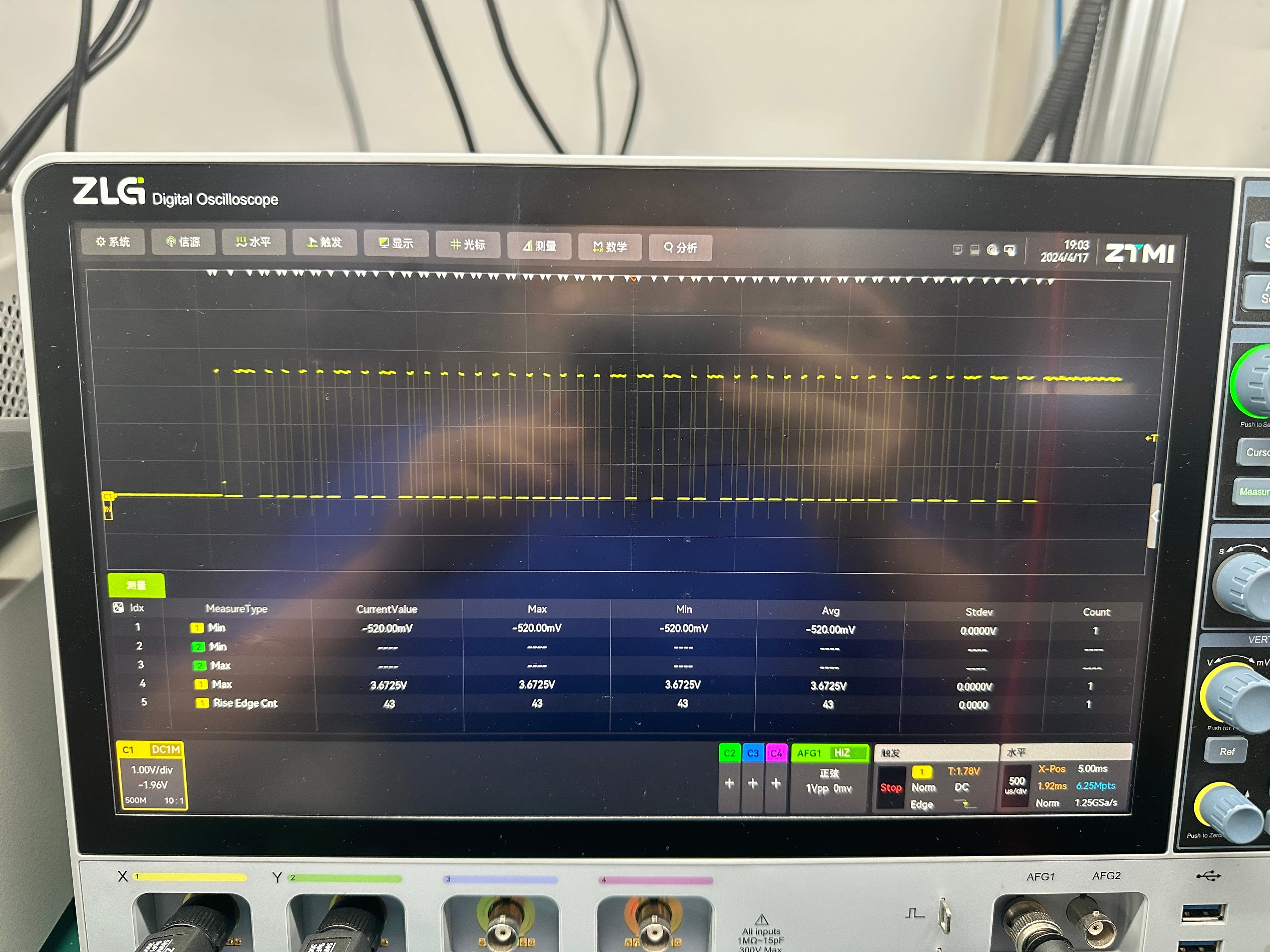
Through observation with the oscilloscope, We clearly saw that there are 43 level changes in the picture. According to the description in the datasheet of DHT11, after the initialization level of a part of the MCU, it is the data bit signal of DHT11.
