Group Assisnment Week 4 - Electronics Production
This week’s assignment included the following tasks:
- Characterize the design rules for your in-house PCB production process: document feeds, speeds, plunge rate, depth of cut (traces and outline) and tooling
- And send a PCB to a board house.
The CNC machine in the ChaiHuo Lab
In the Chaihuo Fab Lab, this is the CNC machine we are using:
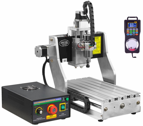
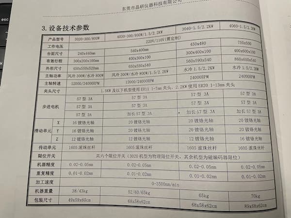
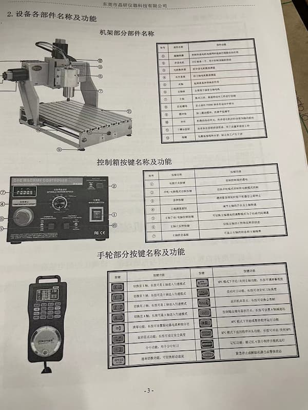
Here is more information aboout it.
It is represented by JingYan Instruments Technology and here is the each function of the mahcine and the detailed specification:
And there are differnt types of tools as well, including 1/64, 1/32 and V-bits that are mentioned in the class:
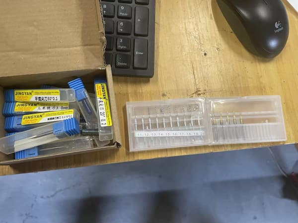
The V-bit example from the class exhibition looks really good and I decided using this type of tool.
How does whole thing work
It requires "G-code" to make the CNC machine work. And there are multiple ways to generate G-code.
G-code is a language that is used to control CNC machines. It provides the necessary instructions for these machines to perform tasks such as cutting, drilling, or engraving materials. The language includes commands that dictate the movement of the machine along its axes, control the speed of the movements, manage the tool operations, and other specific actions required to shape the material according to precise specifications.
- Option 1: Directly using "Mods CE" tool to generate the G-code, it requires PNG or SVG images since they are lossless resolution.
- Option 2: Uploading the Gerber files to the related software of the CNC machine and let it generate the code.
For both options, they all require the configuration of the parameters, which mean I need to know and need to:
- How thick is the board so that I can set the depth of the cut
- Set different parameters for different tools(1/64 end mill, 1/32 end mill, V-bit, etc)
- Set a reasonable width to keep the connection simple without cutting it
- Set the original point(zeroing)
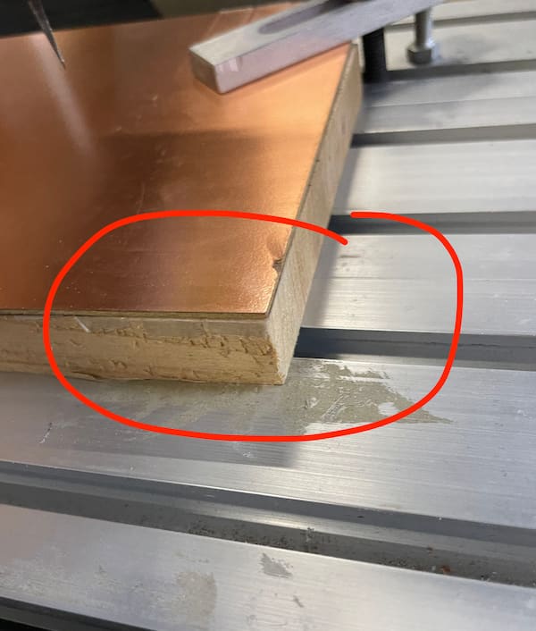
For the safety and the lifetime of the machine and the tools, there are something that need to be awared:
- There should be a backing plate under the cutting board, which is generally wood
- The base and the board to be cut should be secured
- Determine the position at the beginning, ensure the origin, do not click "return to the origin" until you have a clear orientation
These are the preparations for cutting.
Testing and Recording
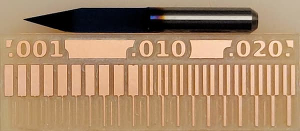
We first got the example PNG files to test different end mills:

- The first one is the interior, for cutting off the edge of the board
- Second one is trace for the 1/64 end mill
- Third one is trace for the 0.4mm V-bit.
We put the files into the machine and let it cut. Here is the output:
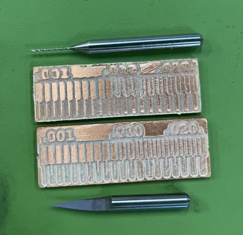
Looks different, the V-bit output is more good-looking for me.
Getting Started
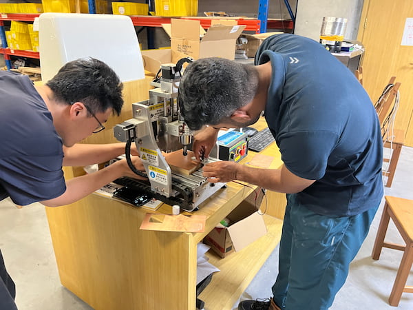
First, Salman helps us output the required files:
and we input it into the software controlling the machine:
The cardboard will always have one corner cocked up, so we used double-sided tape in addition to the retainer.
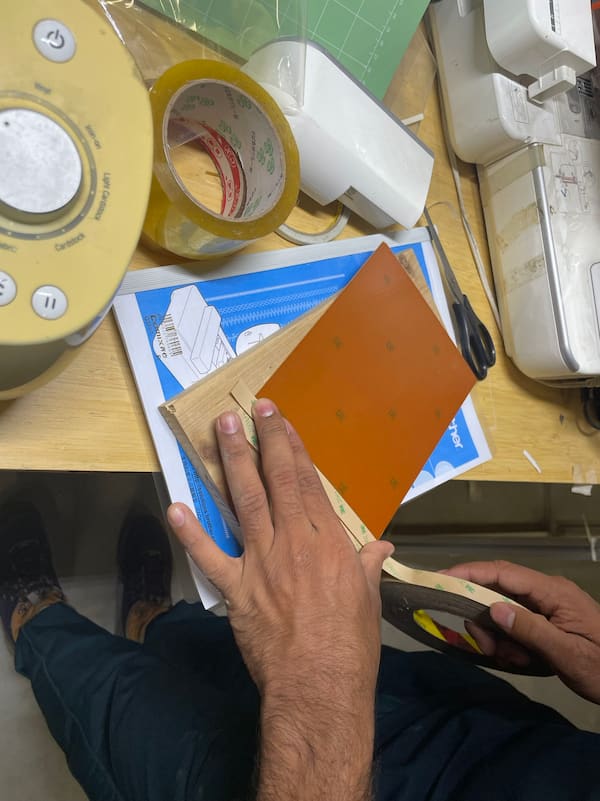
Then we we re-fixed it.
Safety is important
The safety is really important:

Wear safety goggles to protect against sputtering:

I did the ".png to .nc" file, the G-code file, before.
It is the time to prepare the end mills:
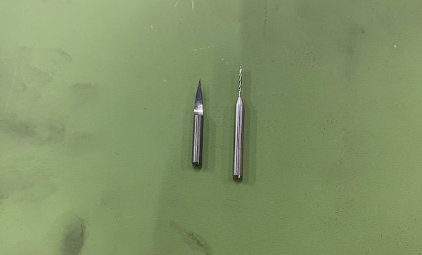
The left one is 0.4mm V-bit and right one is 0.8mm drill.
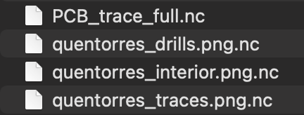
And we have three files:
- Traces-PNG.nc is using 0.4mm V-bit.
- Drills-PNG.nc and interior-PNG.nc are using 0.8mm drill.
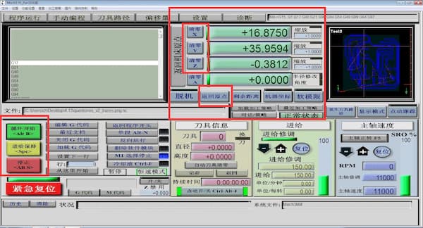
After uploading the rest two, I can upload the ".nc" files to the CNC machine and the files are looking like this:
There are some parameters on the software:
- The position of the cutting tools
- The reset posotion button
- Start, hold, stop buttons
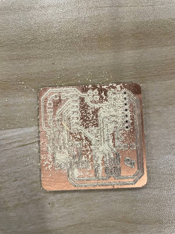
After clicking "Start" button, the machine will begin the cutting and drilling:
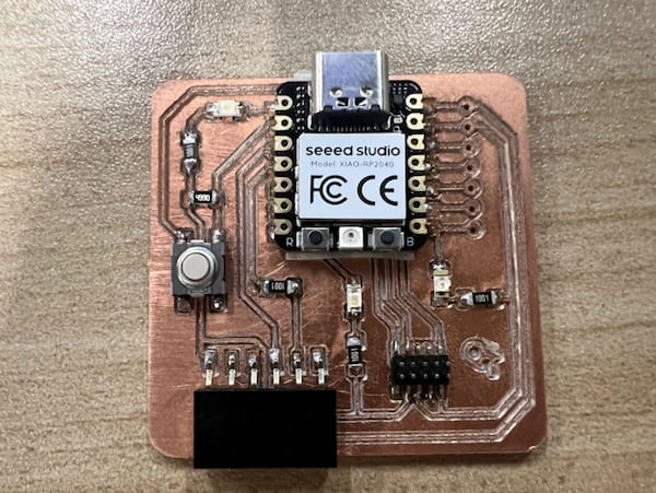
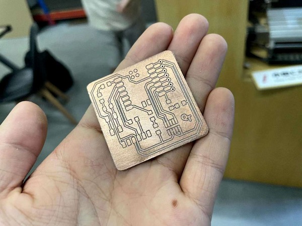
After cutting I got the board:
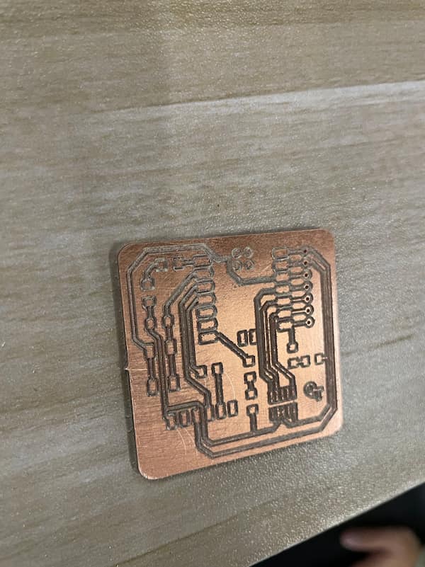
Rub with sandpaper to finish shaping:
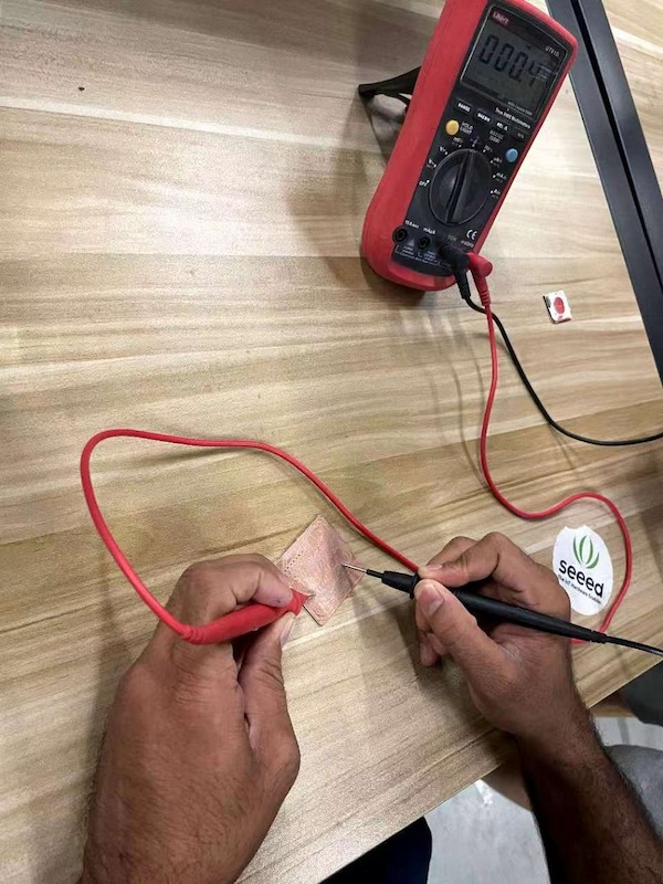
For every board we need to test if it is shortcircuit:
Some other boards we mill:
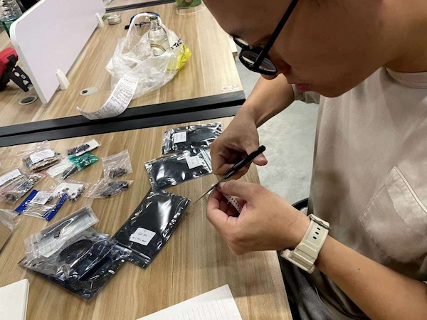
Next we are finding components that we need to solder:
Soldering:
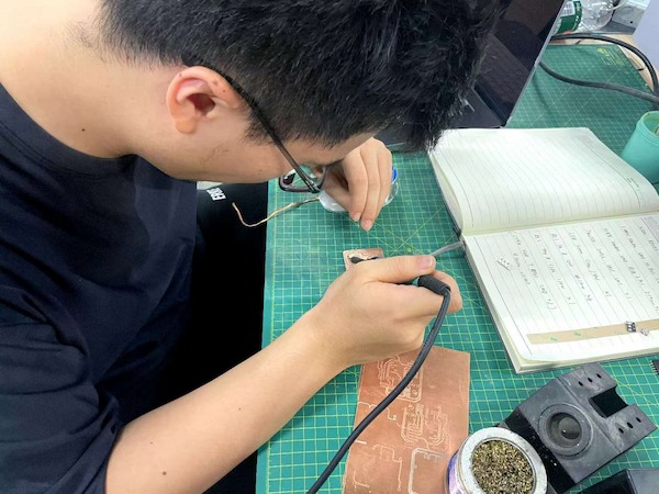
we have each soldered board on our individual pages.