Blot - Mechanical Design Machine Design
Write something at the front
In this group assignment, we are going to reimplement the BLOT, the plotting bot from hack club, presented by our friend - Leo and his teammates.
The Seeed Studio is hosting a Maker Camp event and at the first we invited 10 MIT researchers to co-create meaningful and open source hardware projects in Shenzhen, explore the tech ecosystem frontier, and join maker networks to explore the local scaling power. Leo was joining us and sharing his idea with us.

Principle of the Machine
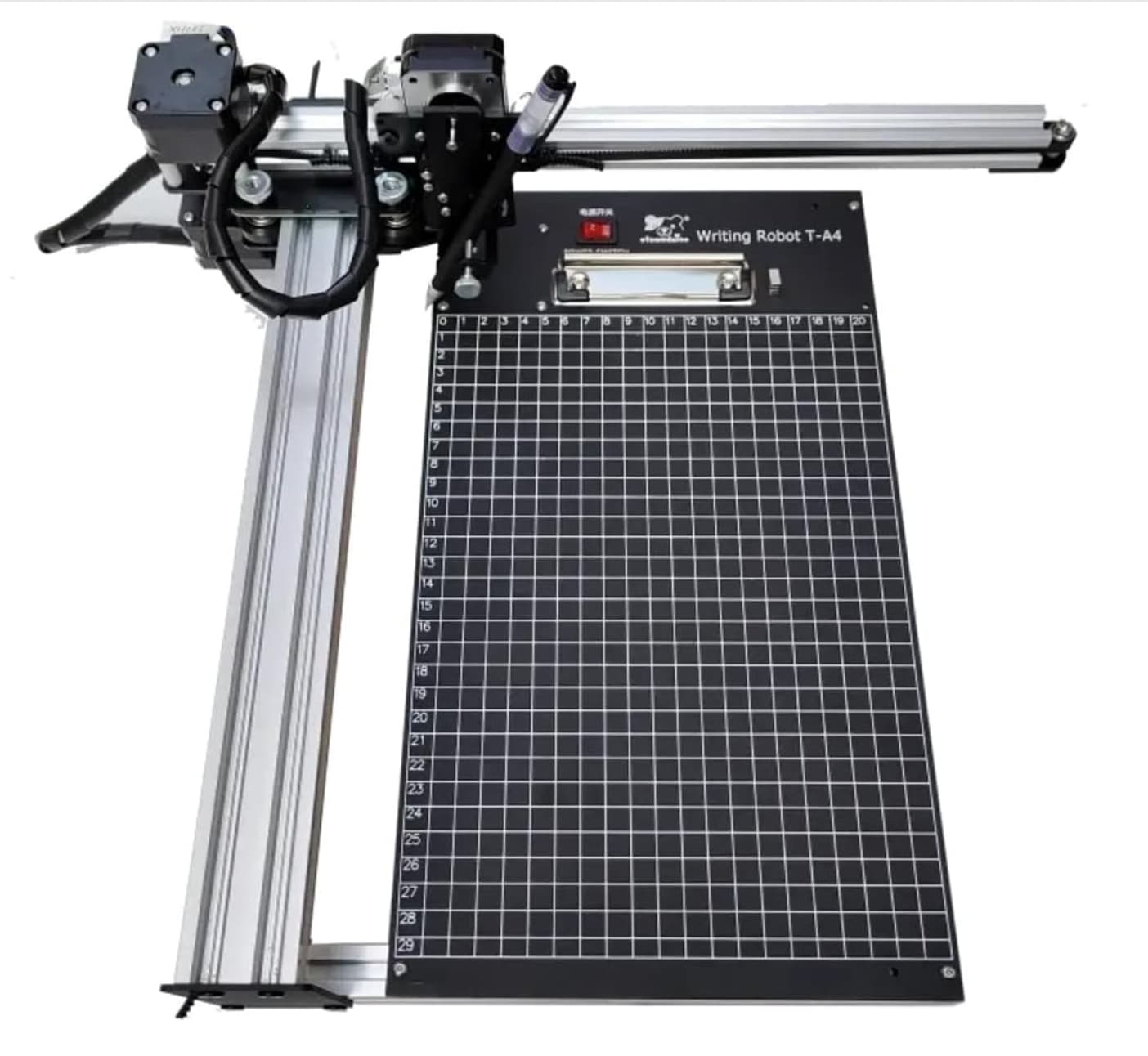
The entire writing machine needs to move on a 2D plane. The X and Y axes are driven by stepper motors, which can accurately control its movement on the writing frame plane. At the same time, there should be a servo to control the up and down movement of the pen barrel.
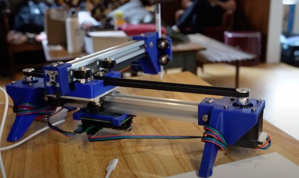
The most important part of the project was to design a mechanical structure that could move freely in the x and y directions. However, none of the team members had any mechanical design experience. Instead, we searched online and found several options. One of the most popular structures is one that uses the x-axis and y-axis as the main axes. In other words, the system has two stepper motors, each controlling one axis.
When the x-axis motor is started, it will move along its rotation line, and the entire platform only moves on the x-axis. One of the advantages of this design is that the mathematics of motion are very simple and easy to calculate. For example, if we want to move from point (0,0) to point (10, 20) in centimeters, we only need to move one motor 10 cm at the same time and the other motor 20 cm at the same time.
Another advantage is that the structure is very easy to design. It looks like the xy plotter in Figure 2. The disadvantage of this design is that since the two motors are located on different axes, one motor will be fixed and the other motor must move with the bracket that holds the pen, creating more vibration and requiring more space to increase stability.
This project is an open-source endeavor requiring us to build the machine from scratch, from sourcing materials to processing and assembly. We've broken down the tasks into several key phases:
- Mechanical Design and Production
- Materials Selection: Choose appropriate aluminum profiles.
- Components: Source all parts necessary for mechanical movement.
- Assembly: Follow specified dimensions to assemble the components, ensuring that two motors can control the movement along the X and Y axes.
- Electronic Design and Production
- Circuit Design: Redesign the circuit board, documenting the process from schematic design to PCB layout.
- PCB Fabrication: Process and fabricate the PCB.
- Debugging: Test and debug each module of the circuit board to ensure functionality.
- Software Design and Debug
- Programming: Use the XIAO main controller board and stepper motor drive module for programming.
- Debugging: Systematically debug the software to manage and control mechanical movements effectively.
- System Integration & Debugging
- Assembly: Combine all mechanical and electronic components.
- Debugging: Implement limit settings and other necessary configurations during this critical phase to ensure smooth operation.
- Video & Poster Promotion
- Promotional Materials: Develop video and poster presentations to showcase the capabilities and design of our machine.
Each of these phases is crucial for the successful completion of the project, requiring detailed attention and coordination among team members.
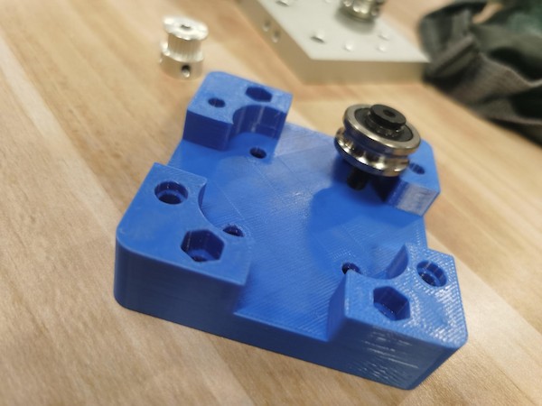
3D Parts Printing
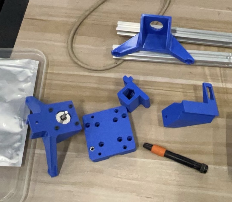
Reference by Blot GitHub repo, we have the parts for 3D printing.
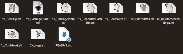
And we used Bamboo A1 Mini to print it:
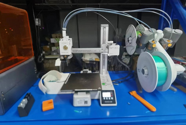
Done and well fit:
Hardware Assembling Part
Since the 3D printing parts are done and we are coming to an integration point. The material collection phase is really time-consuming.
We tried to unload other parts and reuse their components:
and it doesn't work out:
Later we have to refer to the material list here, and try to order them online:
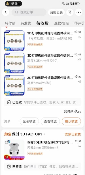
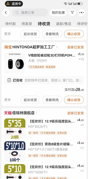
The purchasing part really takes time:
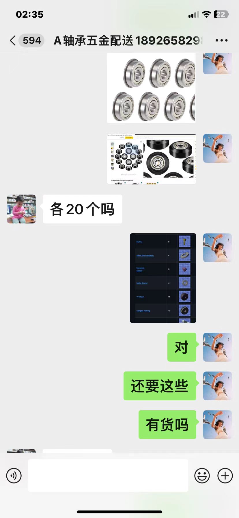
There are still parts we are missing:
and we start to disassemble our 3D printers(some parts are just hard to order):
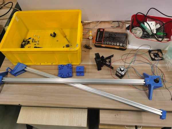
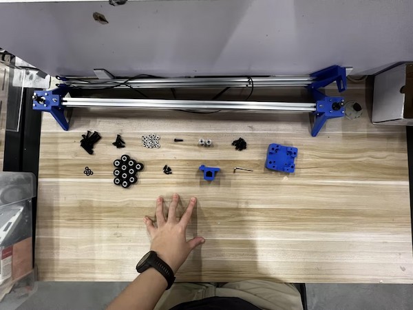
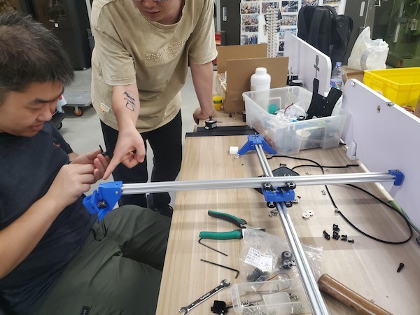
Finally we got almost all the parts and start to assemble:
The one on the back
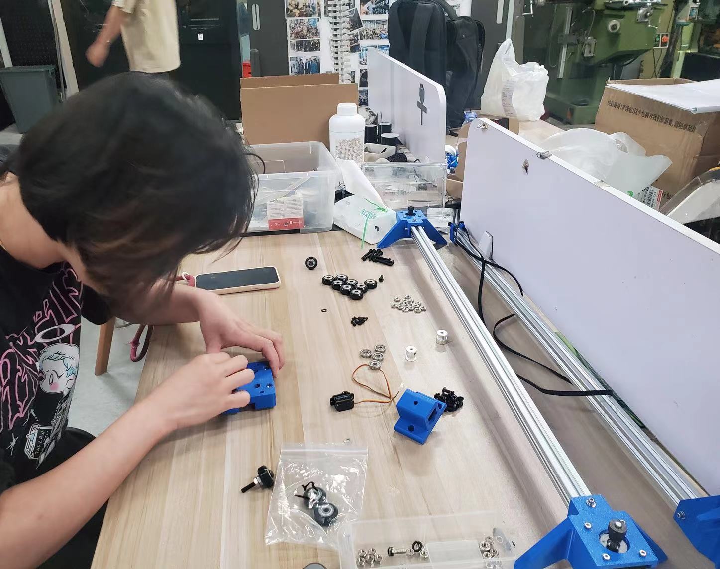
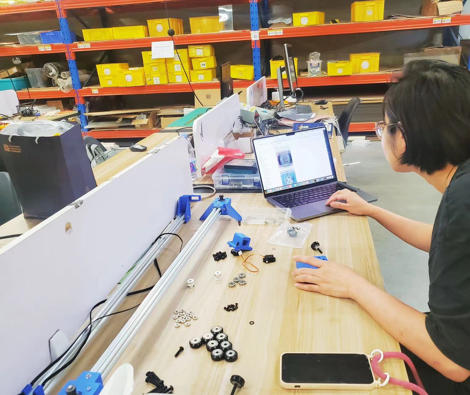
The main one:
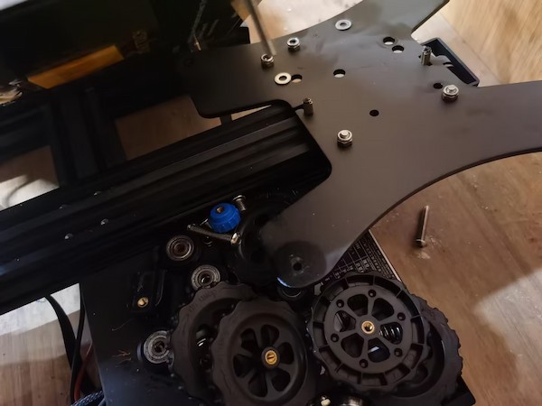
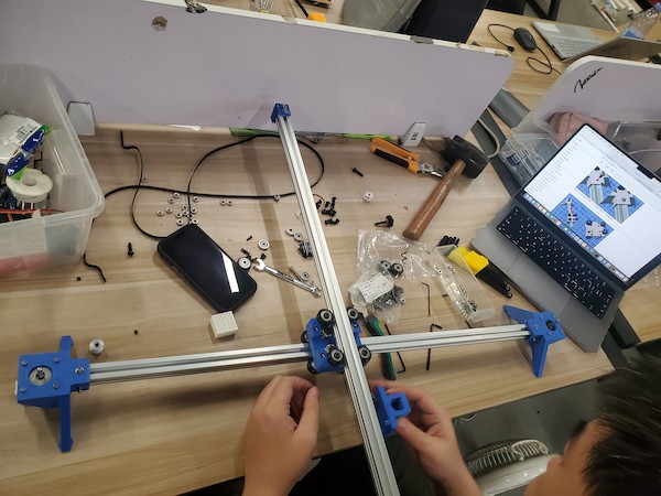
Add the main middle part to the Aluminum Extrusion:
looking good:
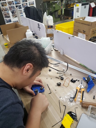
Then we can move to the part securing the pen:
Fix the servo motor:
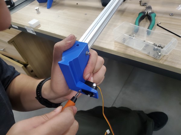
Done!! XD
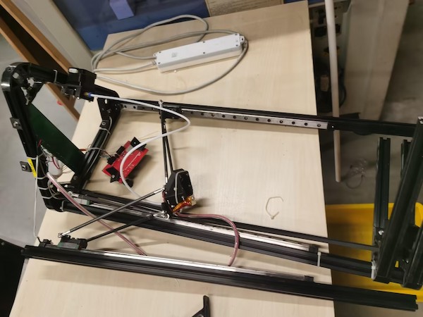
Ops! The belt not long enough!
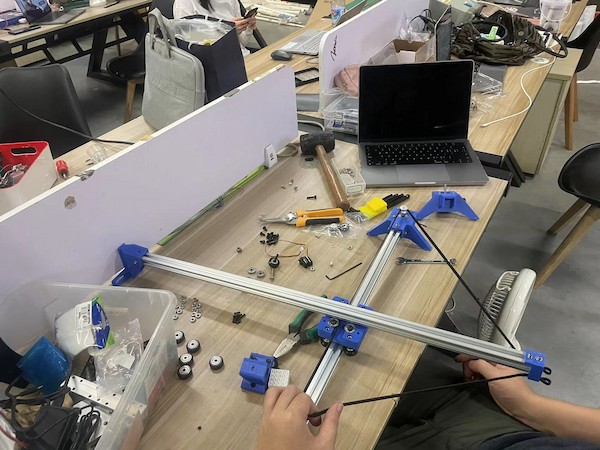
Why... It is becasue we are having much longer Aluminum Extrusion, which is almost 800mm. And the original one is 250mm...
This we think might cause some problems... like the equilibrium problem...
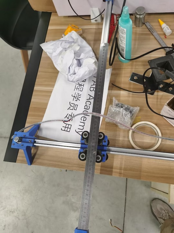
Anyway, later we are able to find the right length belt and assemble it as well:
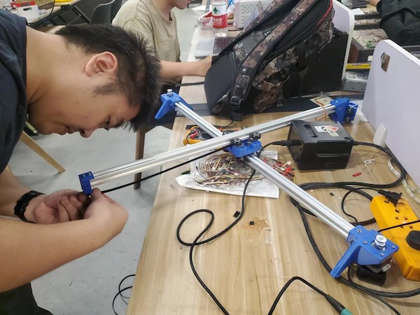
Assembling Done!
Hardware and Software Testing
For the next, I am going to test whether the hardware is functional and program the software.
Knowledge about the Kit
But at the fitst, we think we should know some principles.
System Integration
- Stepper Motor: It is used to control the movement of the X and Y axes. Each motor is connected to a shaft, which is rotated to move the corresponding shaft.
- Belt: It is attached to the stepper motor, used to convert the rotational motion of the motor into linear motion.
- Guide Rails(Aluminum Extrusion) and Sliders: Used to support and guide the linear movement of the platform on the X and Y axes.
- Controller: Usually a microcontroller or computer that sends a pulse signal to the stepper motor driver, thereby controlling the stepping and direction of the motor.
- Stepper Motor Driver: accepts the pulse signal of the controller and drives the stepper motor to move accurately
Operating Principle
Each stepper motor controls its rotation Angle through a pulse signal. The rotation of the stepper motor is converted into the linear motion of the platform by the belt system. THe operating can be simple:
Initialization: When the system starts, the controller moves the platform to the initial position (usually detected by a limit switch).Receive Instructions: The controller receives coordinate instructions entered by the user (for example, G-code instructions sent from computer software).Sending Pulse Signals: The controller sends a pulse signal to the stepper motor driver, which converts the pulse into the motion of the stepper motor. Linear motion: The stepper motor rotates to drive the lead screw or belt to move the platform to the specified position on the X and Y axes.- In this case,
XIAO RP2040will send pulse signal toA4988motor driver and the drivers will convert the pulse into the motion of the stepper motor. Calculation Path: Based on the current position and target position, the controller calculates the number and direction of pulses that need to be sent to each motor.
Since it is similar to the 3D printer principle, I will add some principles about these operating here as well:
Feedback and Adjustment: Some advanced systems may have a position feedback mechanism (such as a grating ruler) to ensure that the platform reaches the target position precisely. If deviations are found, the system fine-tunes them.
Controlling Methods
There are different methods can control the the motor. And the key to control the stepper motor is to control the frequency and number of pulse signals:
Single-step Control: Each pulse signal drives the motor to rotate at a fixed Angle (called a step). The motor is controlled to rotate multiple steps by sending multiple pulse signals.Microstep Control: Improve the resolution and accuracy of the motor by subdividing each step. For example, one step is subdivided into 16 microsteps.Speed Control: Control the rotation speed of the motor by adjusting the frequency of the pulse signal. A high frequency pulse will make the motor spin faster, and a low frequency pulse will make the motor spin slower.Acceleration control: In order to avoid sudden start or stop damage to the mechanical structure, it is usually necessary to perform acceleration control on the motor to smoothly start and stop.
Connection about the kit
Refering to this article.
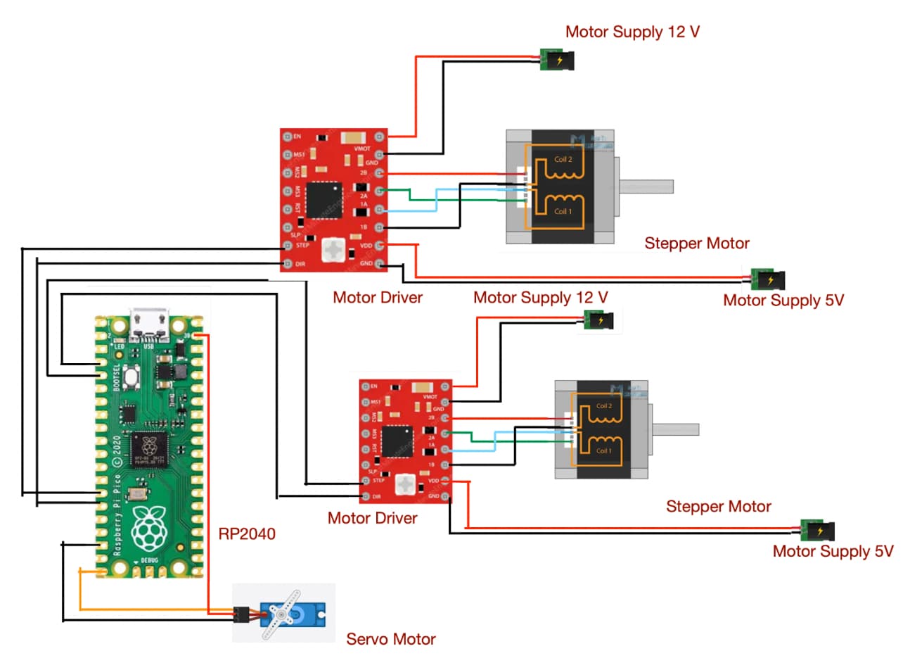
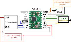
We are going to use only two pins (STEP and DIRECTION) to control the stepper motors. The stepping pin is connecting to D10 of XIAO RP2040, used to control the step, while the directional pin is connecting to D9 of XIAO RP2040, used to control the direction. The stepper motor is powered by 12V power supply, and the A4988 module is powered by XIAO RP2040. Potentiometers are used to control the direction of the motor.
Hence, this is will be the motor 1 connection method:
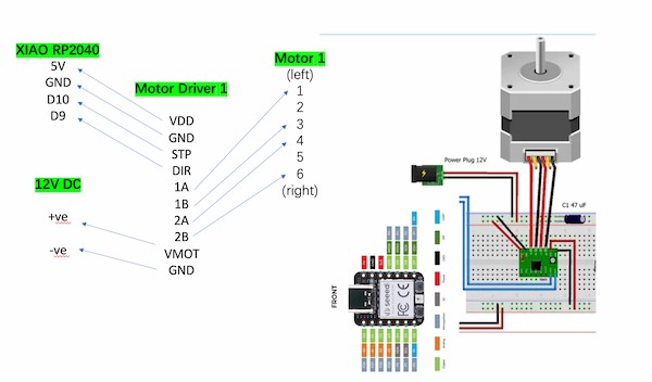
For motor 2 connection, the only change is that The stepping pin is connecting to D10 of XIAO RP2040 while the directional pin is connecting to D9 of XIAO RP2040.
To sum up, it will require one XIAO RP2040 to control two motors.
Software Programming
Testing Code
This is Arduino code, for drawing a oblique line, operating motors, moving the same time on the X-axis and Y-axis.
#include <Arduino.h>

const int STEP_PIN_X = D10;
const int DIR_PIN_X = D9;
const int STEP_PIN_Y = D8;
const int DIR_PIN_Y = D7;

const float STEPS_PER_MM = 80.0; // Adjust this value based on your stepper motor's steps per millimeter
const float LINE_LENGTH_MM = 100.0; // Length of the line in millimeters

void setup() {
  pinMode(STEP_PIN_X, OUTPUT);
  pinMode(DIR_PIN_X, OUTPUT);
  pinMode(STEP_PIN_Y, OUTPUT);
  pinMode(DIR_PIN_Y, OUTPUT);
}

void loop() {
  // Draw a line along the X-axis
  drawLine(0, 0, LINE_LENGTH_MM, 0);

  delay(1000); // Pause for 1 second

  // Draw a diagonal line
  drawLine(0, 0, LINE_LENGTH_MM, LINE_LENGTH_MM);

  delay(1000); // Pause for 1 second

  // Move back to the origin
  drawLine(LINE_LENGTH_MM, LINE_LENGTH_MM, 0, 0);

  delay(1000); // Pause for 1 second before repeating
}

void drawLine(float x0, float y0, float x1, float y1) {
  // Convert millimeters to steps
  int x0Steps = round(x0 * STEPS_PER_MM);
  int y0Steps = round(y0 * STEPS_PER_MM);
  int x1Steps = round(x1 * STEPS_PER_MM);
  int y1Steps = round(y1 * STEPS_PER_MM);

  int dx = abs(x1Steps - x0Steps);
  int dy = abs(y1Steps - y0Steps);

  int sx = (x0Steps < x1Steps) ? 1 : -1;
  int sy = (y0Steps < y1Steps) ? 1 : -1;

  int err = dx - dy;

  while (true) {
    if (x0Steps == x1Steps && y0Steps == y1Steps) break;

    int e2 = 2 * err;

    if (e2 > -dy) {
      err -= dy;
      x0Steps += sx;
      digitalWrite(DIR_PIN_X, (sx > 0) ? HIGH : LOW);
      digitalWrite(STEP_PIN_X, HIGH);
      delayMicroseconds(500);
      digitalWrite(STEP_PIN_X, LOW);
      delayMicroseconds(500);
    }

    if (e2 < dx) {
      err += dx;
      y0Steps += sy;
      digitalWrite(DIR_PIN_Y, (sy > 0) ? HIGH : LOW);
      digitalWrite(STEP_PIN_Y, HIGH);
      delayMicroseconds(500);
      digitalWrite(STEP_PIN_Y, LOW);
      delayMicroseconds(500);
    }
  }
}
Here is the principle:
Stepper Motors:
- For Motor 1:
- Connect the motor driver's STEP pin to the XIAO RP2040 board's pin
D10(defined asmotor1StepPinin your code). - Connect the motor driver's DIR pin to the XIAO RP2040 board's pin
D9(defined asmotor1DirPinin your code).
- Connect the motor driver's STEP pin to the XIAO RP2040 board's pin
- For Motor 2:
- Connect the motor driver's STEP pin to the XIAO RP2040 board's pin
D8(defined asmotor2StepPinin your code). - Connect the motor driver's DIR pin to the XIAO RP2040 board's pin
D7(defined asmotor2DirPinin your code).
- Connect the motor driver's STEP pin to the XIAO RP2040 board's pin
- Ensure that the motor driver's power supply is connected correctly and matches the voltage requirements of the stepper motors, which is 12V.
System Composition
- Stepper motors: The
STEP_PIN_X,DIR_PIN_X,STEP_PIN_Y, andDIR_PIN_Ypins are connected to the XIAO RP2040 to control the movement of the X and Y axes, respectively. - Controller (XIAO RP2040): Send pulse signals to the stepper motor to achieve linear motion by adjusting the rotation of the stepper motor.
How it Works
- Initialization: In the
setup()function, use thepinModefunction to set the pins that control the stepper motor to output mode. - Receive instructions:
The loop()function loops through thedrawLineX()anddrawLineY()functions, sending instructions to control the motor to move a specific distance along the X and Y axes. - Calculate the path: In the
goToMM()function, convert the number of millimeters at the destination location to the number of steps, usinground(x * STEPS_PER_MM)andround(y * STEPS_PER_MM)to calculate the number of steps to be sent. Send a pulse signal: In the goToMM() function, use the digitalWrite function to send a pulse signal to control the stepper motor to move to the target position.
Control Methods
- Single step control: By
digitalWrite(STEP_PIN_X, HIGH)anddigitalWrite(STEP_PIN_X, LOW)anddigitalWrite(STEP_PIN_Y, HIGH)anddigitalWrite(STEP_PIN_Y, LOW)Control the stepper motor to rotate one step. - Direction control: use
digitalWrite(DIR_PIN_X, (xSteps >= 0)? HIGH: LOW)anddigitalWrite(DIR_PIN_Y, (ySteps >= 0)? HIGH: LOW)Sets the rotation direction of the motor. - Speed control: The frequency of the pulse signal is adjusted by
delayMicroseconds(500)to control the rotation speed of the motor.
Code Interpretation
- setup() function: Sets the stepper motor control pin to output mode.
- loop() function: Execute the drawLineX(), drawLineY(), and goToMM(0, 0) functions in order to move a certain distance along the X and Y axes, respectively, and then return to the origin.
- drawLineX() and drawLineY() functions: Call the goToMM() function to move the specified distance along the X and Y axes, respectively.
- goToMM() function: Converts millimeters to steps.
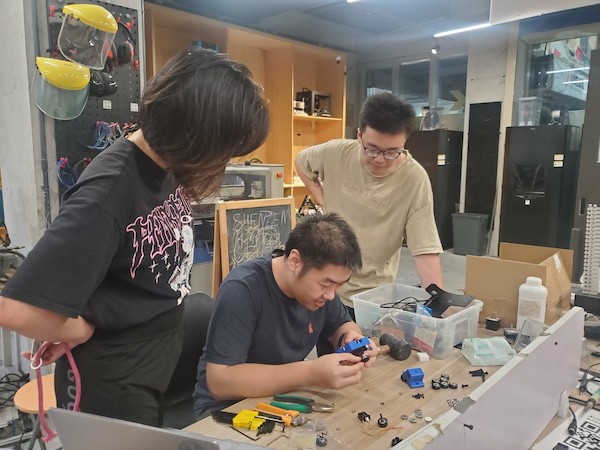
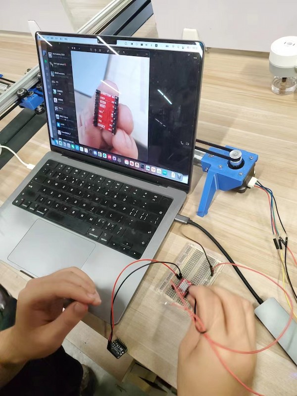
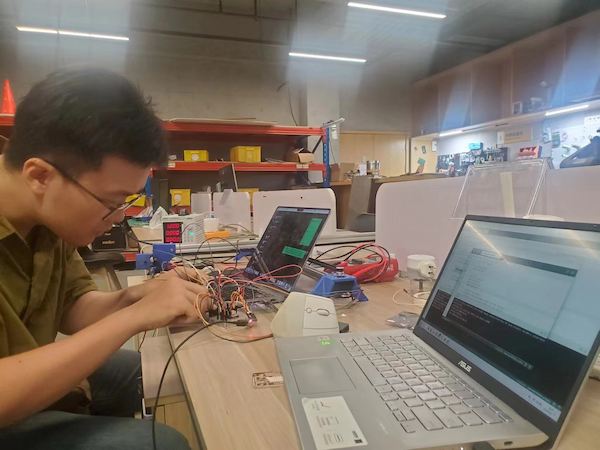
Real Connecting
This is really hard one.
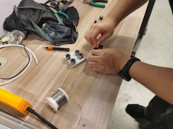
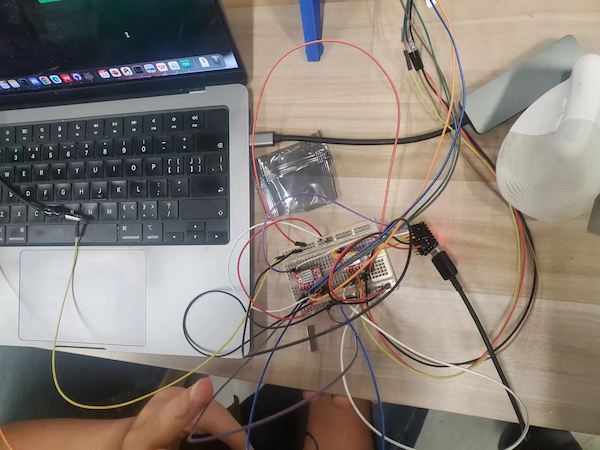
We are using one XIAO RP2040, two A4988 motor divers, and two step motors, and connecting them on one breadboard, for the testing.
First, we need longer wires...
Then I refer to this article before, and connect the components with the example connection.
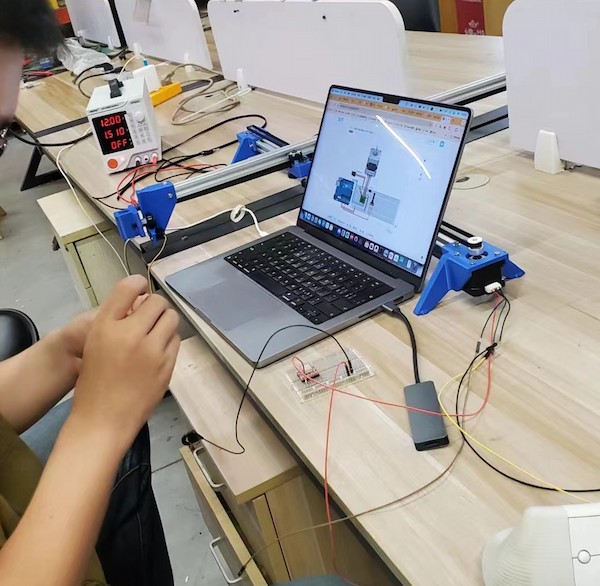
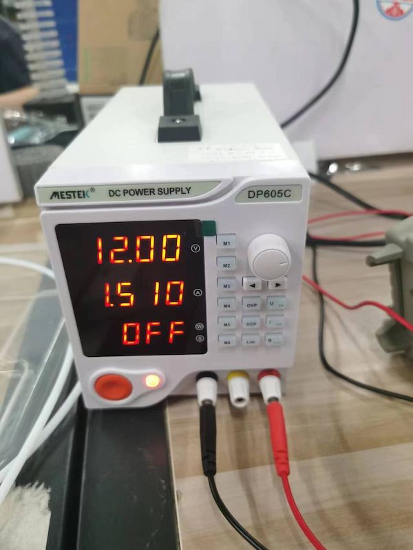
For 12V power supply, I am using a DC power supply, setting 12V.
Connecting XIAO RP2040 and the A4988 motor diver, with schematic diagram.
Done for motor 1.
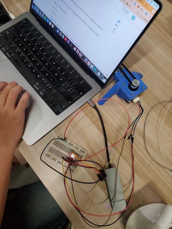
Upload a simple code for testing there is no short circuit.
Then connecting another one:
After burnning 3 drivers... and keeping wrong moving...
debugging...
Connection lost - not holding well.
debugging...
Stuck - adjust the pulley
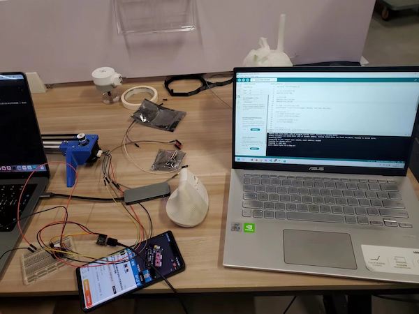
I got the final version of connection at last:
And testing finally good:
PCB Design
Because this project is originally a popular open source project, there are many reference circuit diagram designs on the Internet. Based on the relevant reference circuits, we will also make our circuit diagram.
In this circuit diagram, I modified two parts.
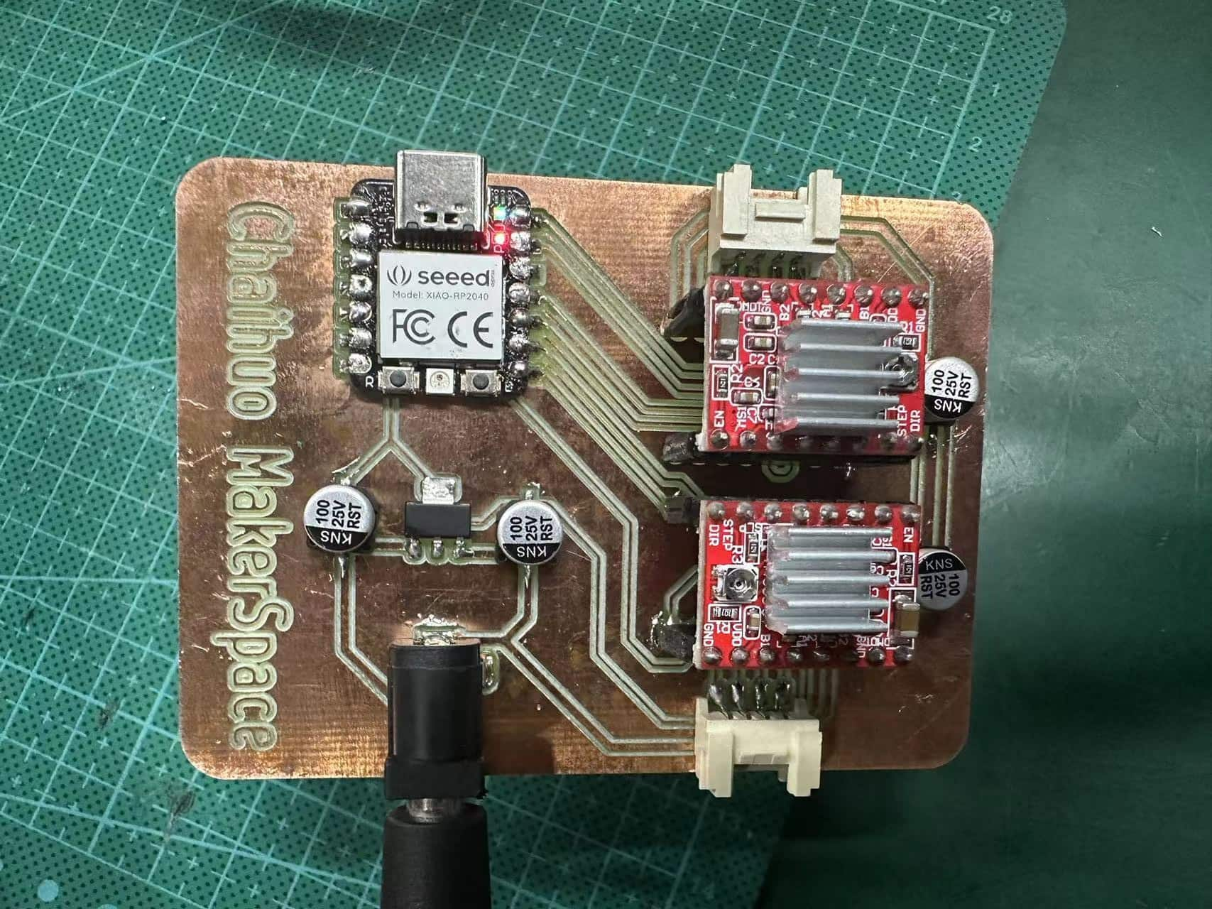
- One is that I changed the main controller inside from Raspberry Pi Pico to Seeed Studio XIAO RP2040.
- The other is that I added a power conversion chip model NCP1117. Through this power conversion chip, a 12V power supply can be directly used to drive the entire main control board and circuit board.
To move the pen position in the x-y plane, we use two bipolar stepper motors. Each stepper motor consumes 12 V / 2 A. I power the stepper motor through a 12V/2A DC power adapter, and at the same time output 5V power through the NCP1117 power conversion chip to supply power to the XIAO RP2040 main control board and 2 stepper motor drivers.
To control the stepper motors we used two A4988 stepper motor drivers. The motor driver requires 3-5 volts of power to operate.
I did not supply 5V voltage to the stepper motor driver separately, but used the same power conversion chip to supply power to the main control board and stepper motor at the same time. But before the test, I actually didn’t calculate whether this solution was feasible.
Each motor has four wires, forming two coils.
(The black and green wires make up one coil, and the red and blue wires make up the other coils. These four wires are connected to pins 1A, 1B (one coil) and 2A, 2B (one coil) in the motor driver. Each motor The drivers both take two inputs from the microcontroller: step size and direction. Whenever the step size pin changes from 0 to 1, the motor will move one step. When the direction pin receives a 1, the motor moves counterclockwise. When the direction pin receives 0, the motor moves clockwise. We also use an SG90 servo motor to control the lifting and lowering of the pen holder. The servo motor is controlled by the PWM signal sent by the microcontroller.)
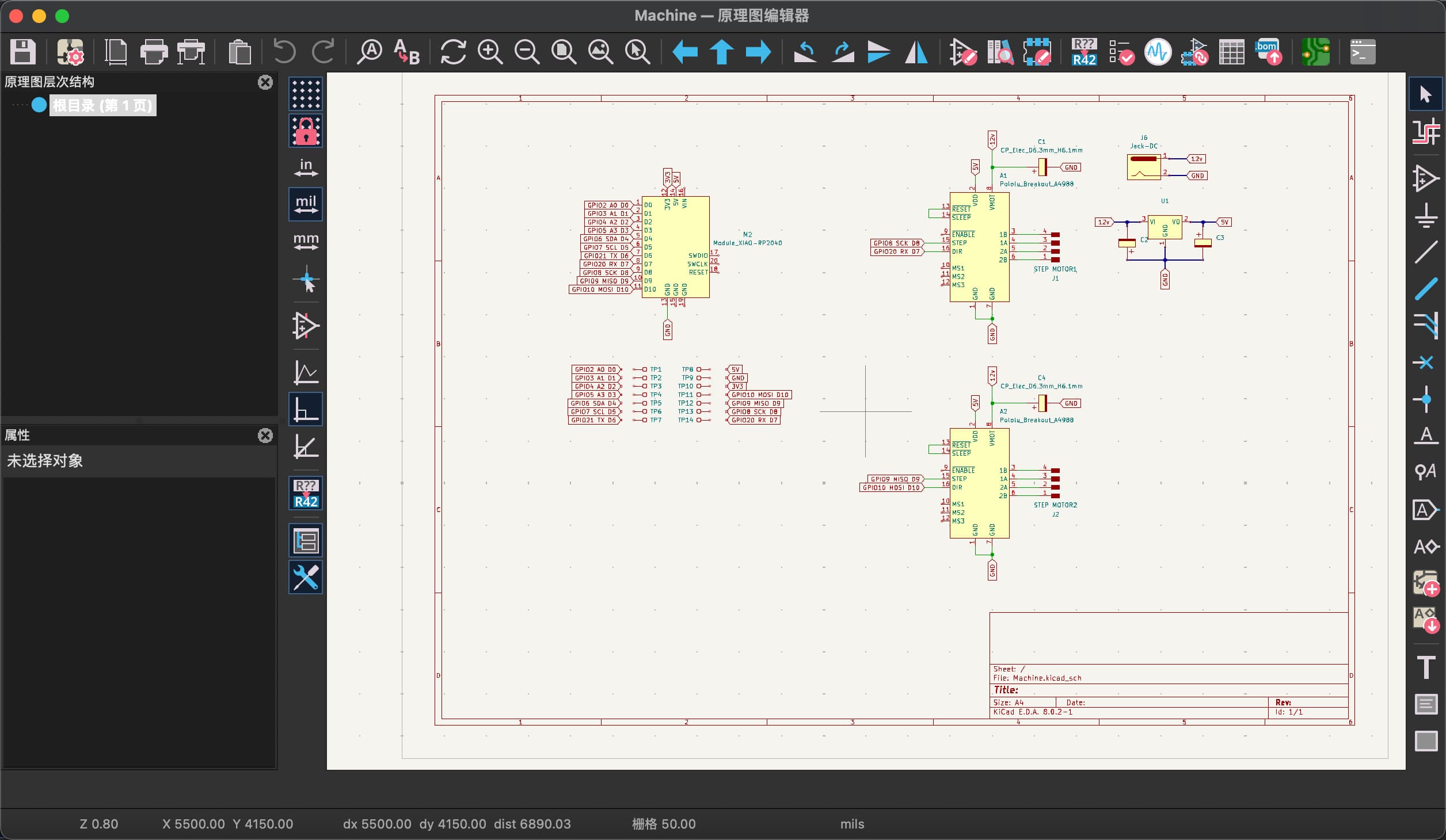
Schematic Design
In the schematic design part, I still used the module design.
- First define the relevant connection signal pin marks of the main control module.
- To design the power conversion module part, refer to the reference design diagram of the power conversion chip. I must give the pins two polarity capacitors. Since there are no 10uf capacitors in my laboratory, I use 100uf capacitors in the actual circuit. This will also make my circuit more stable.
- The last step is the circuit design of the two stepper motor drive modules. I also referred to the reference design diagram of the stepper motor drive. In order to ensure that the stepper motor drive is not burned out, I also added a capacitor to the power supply end of the motor. , thereby achieving the function of protecting the circuit.
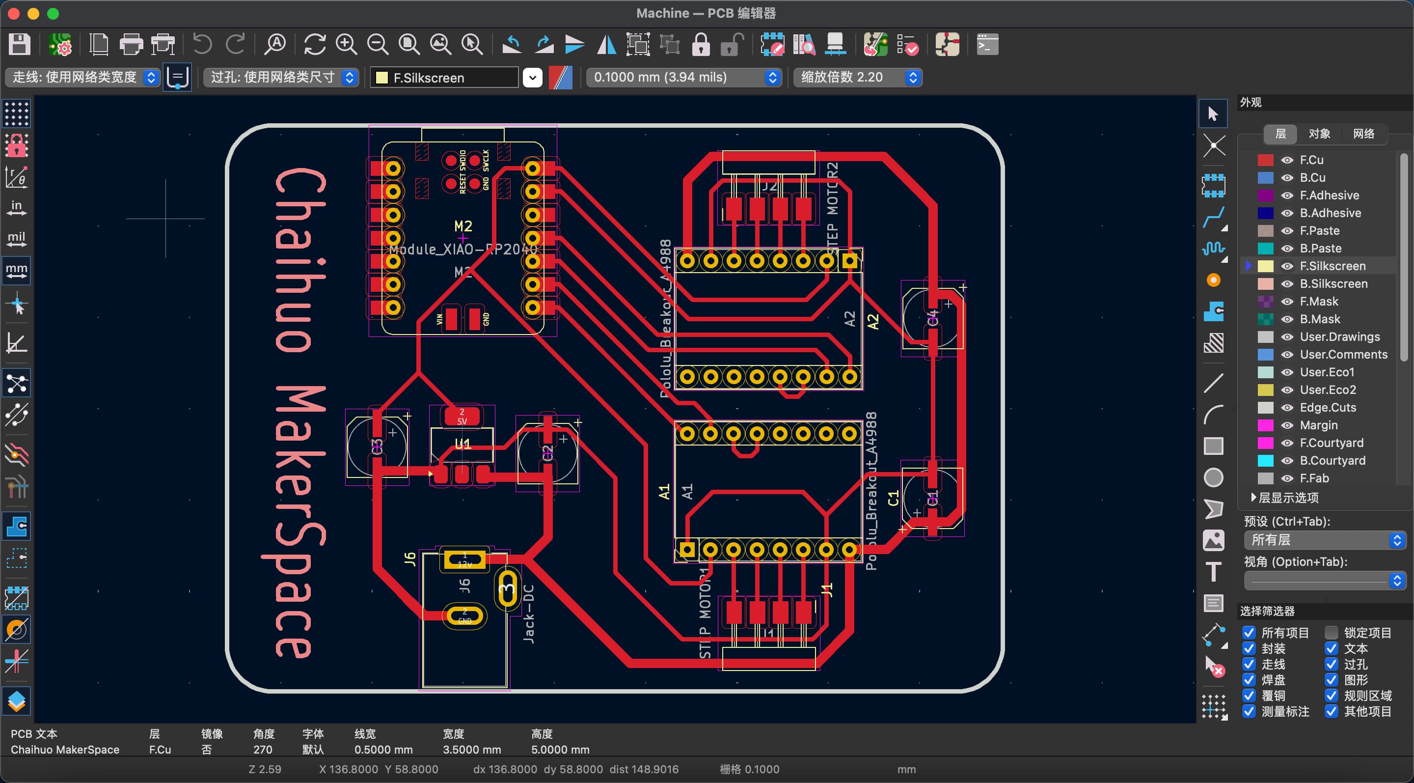
PCB Design
The PCB design part is a test of design ability, because it must not only ensure complete functionality, but also ensure aesthetics. In this process, a lot of time was actually spent on arranging and laying out the components.
I made the power supply part and signal line part thicker to facilitate subsequent processing, but the pads were still too small, making subsequent processing more difficult.
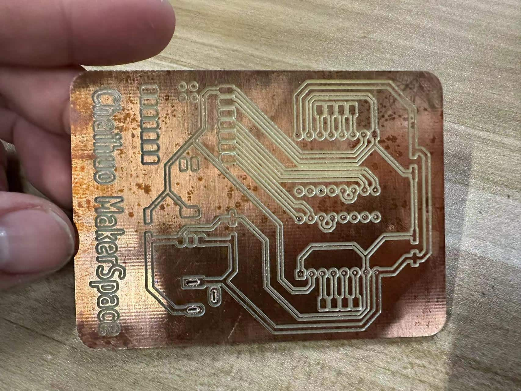
Milling the PCB
- Export the manufacturing project file with Gber format in KiCad.
- Import the project file to generate a PNG image via Gbertopng site.
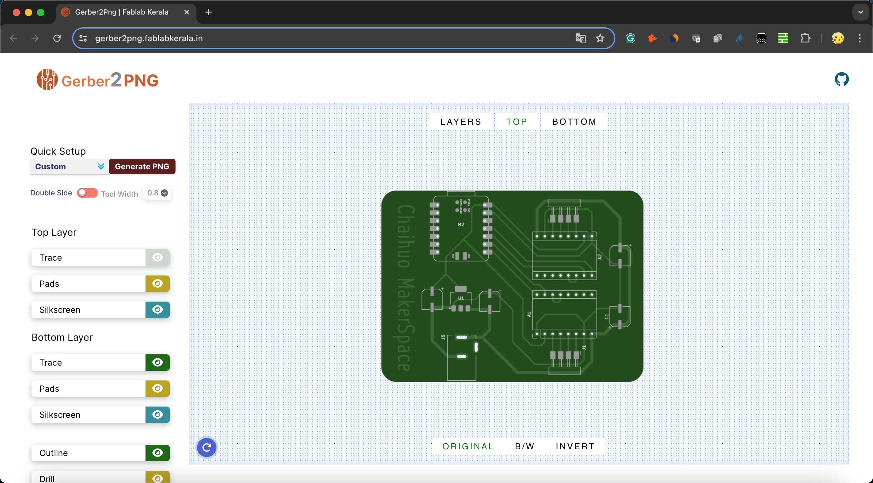
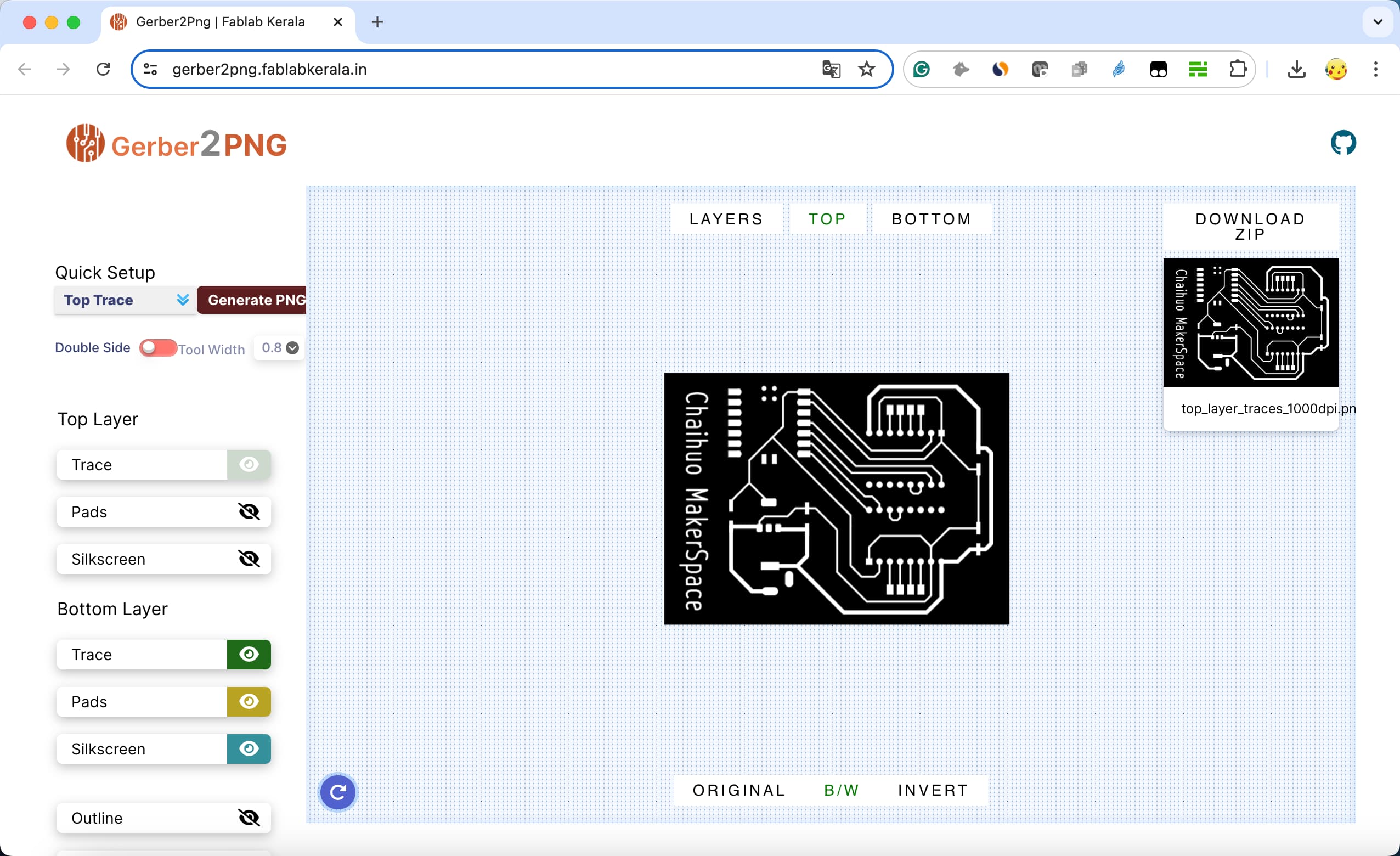
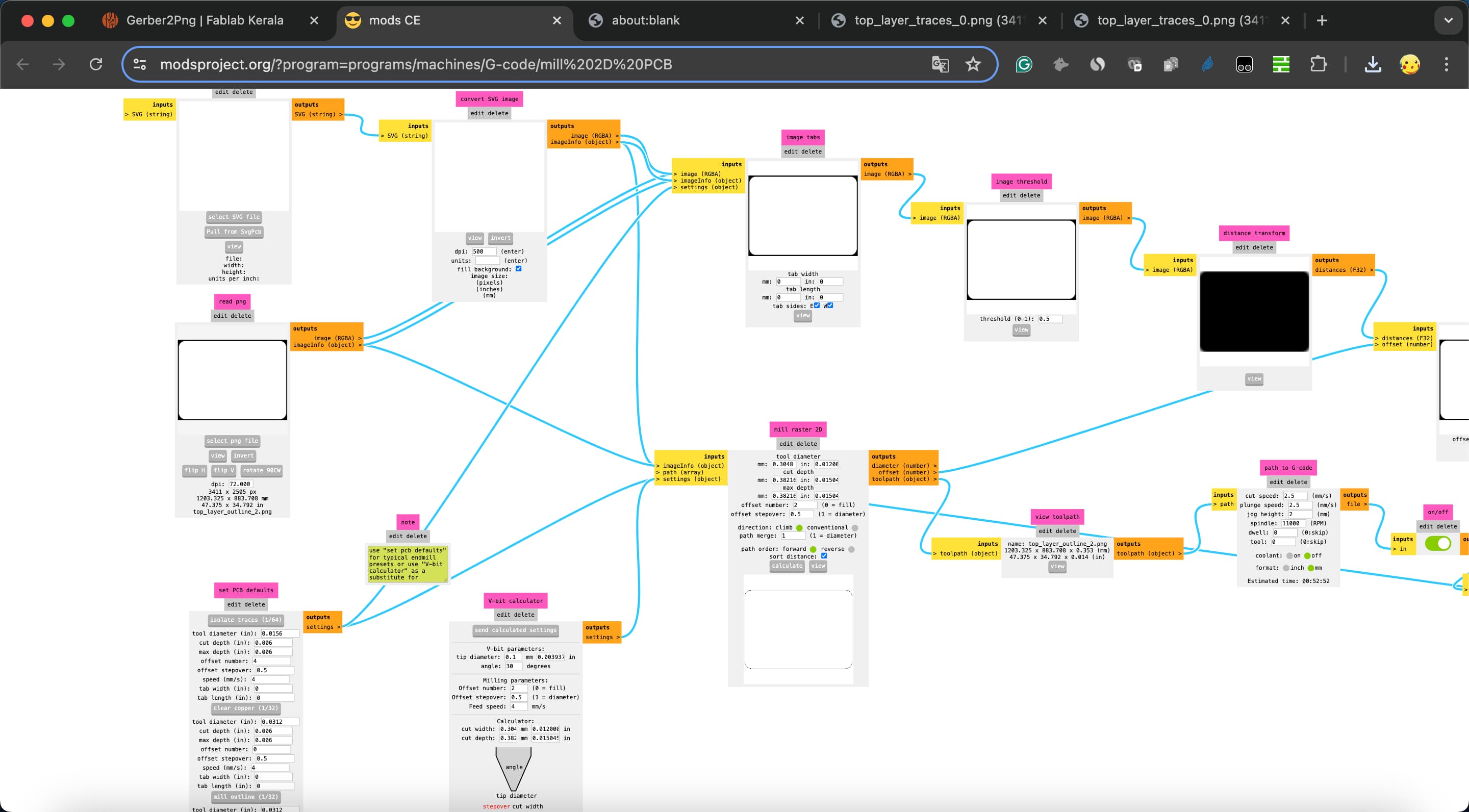
- Then import the PNG images to the Mos website to generate NC files. This process is the same as making circuit boards in the previous lessons.
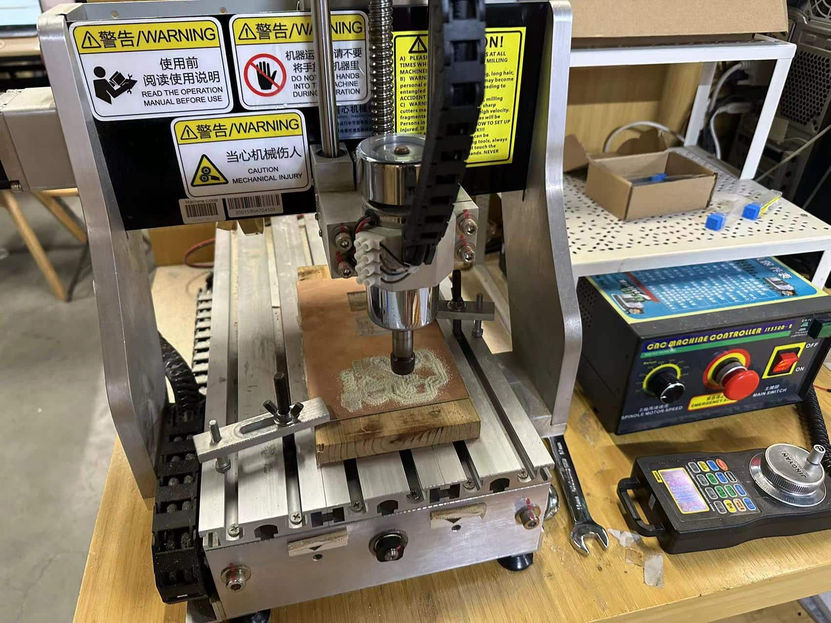
- Milling
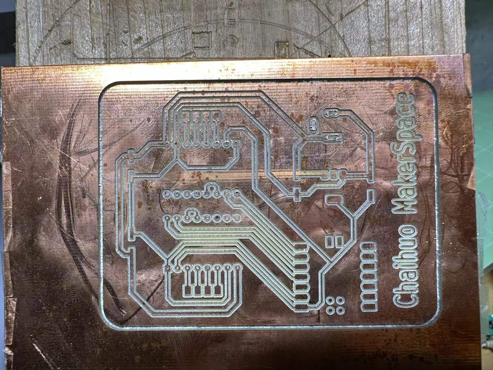
- The finished PCB board is shown below. The effect is quite satisfactory.
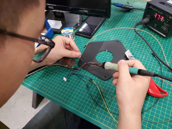
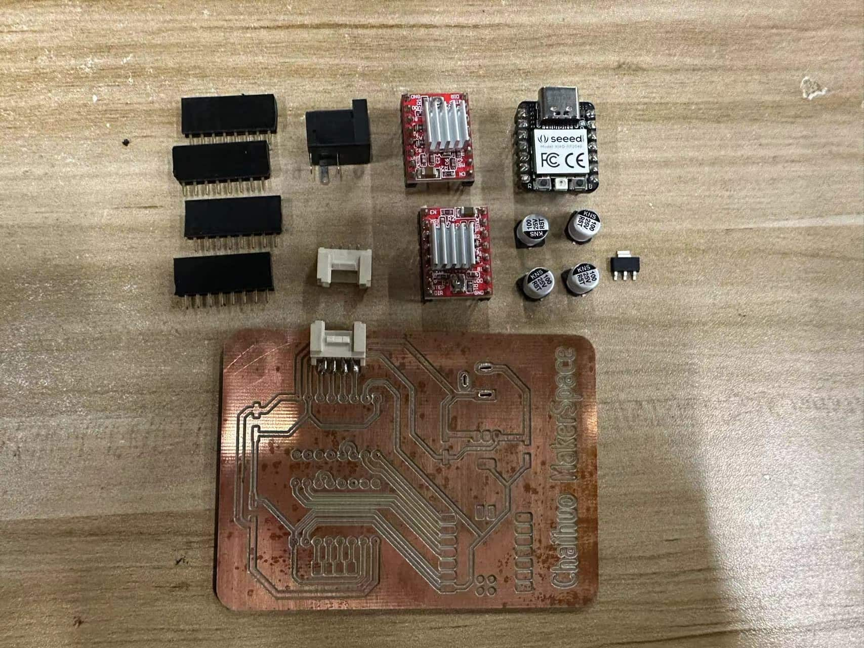
Soldering & Testing Circuit Board
- First prepare the required electronic components and the prepared circuit board. Because the drilling process is not very smooth, I cannot use a carving knife to enlarge the hole in the power supply welding part, otherwise there is no way to weld.
- The board after welding is as follows. I can only lightly fix the welded pins on the board. There is no way to drill through the holes. This will also give the stepper motor driver module, which generates serious heat, enough space for heat dissipation.
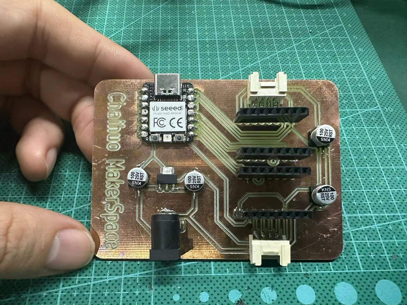
- After the welding is completed, I first measure it with a multimeter. Make sure that there is no short circuit in the circuit, and also make sure that the various signal lines of the circuit are connected according to the parts I want.
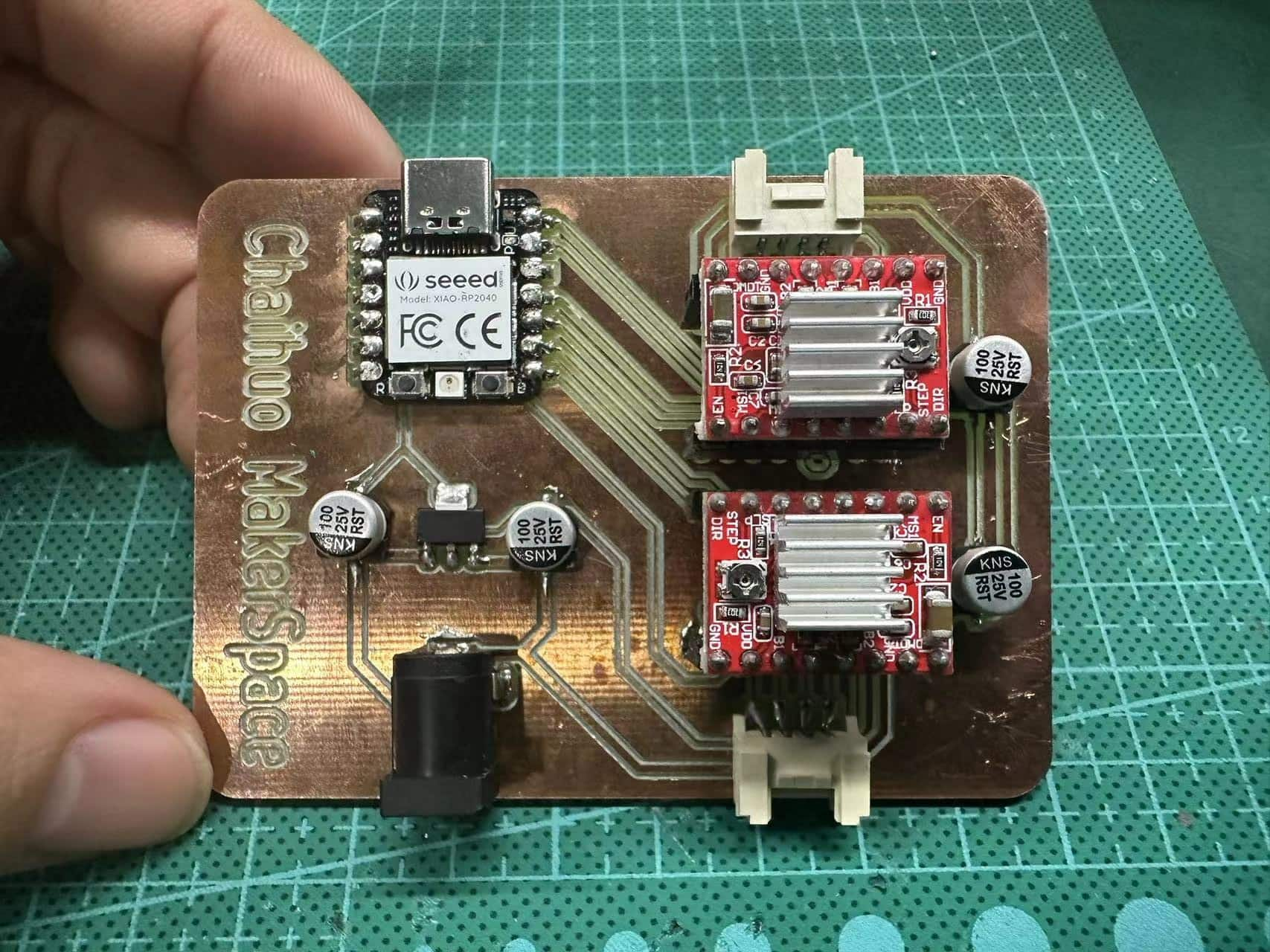
- When everything is measured, power on and measure. The board can work normally and the program can be successfully downloaded through the Arduino IED.