Group Assisnment Week 8 - Electronics Design
This week’s assignment included the following tasks:
- See the test equipment in your lab to observe the operation of a microcontroller circuit board
- Send a PCB out to a board house
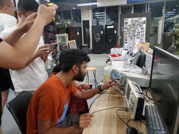
The Oscilloscope in ChaiHuo
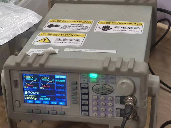
This is the Atten DDS function signal generator 20MHz:
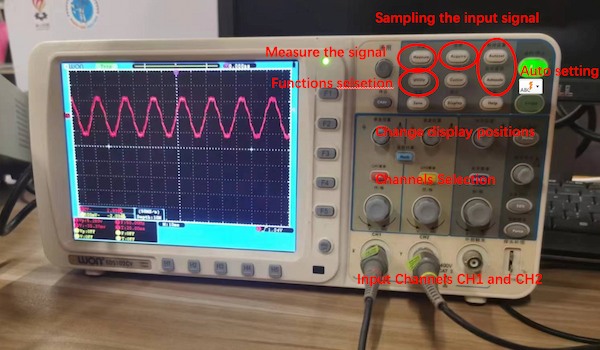
This is the OWON EDS102CV
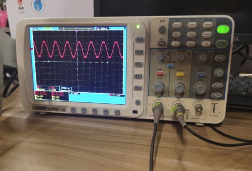
We will use signal generator to generate sine wave and use oscilloscope to measure it.
Introduction to Oscilloscope
An oscilloscope is a powerful and versatile electronic test instrument that allows you to observe the varying signal voltages in electrical circuits. It graphically displays these voltages as waveforms, showing how signals change over time. This makes oscilloscopes essential for viewing and analyzing the behavior of electronic devices, particularly for diagnosing malfunctions and ensuring system stability.
- These voltage waveforms are displayed graphically.
Key Features of an Oscilloscope:
- Display: Oscilloscopes use a screen to display the waveform of electrical signals in a graph-like format, where the vertical (Y) axis represents voltage and the horizontal (X) axis represents time.
- Channels: Most oscilloscopes have multiple channels that can simultaneously capture and display signals from multiple sources.
- Bandwidth: This indicates the maximum frequency range the oscilloscope can accurately measure.
- Sampling Rate: This is the speed at which the oscilloscope takes samples of the signal. A higher sampling rate allows better representation of fast-changing signals.
- Triggering: Triggering functions help stabilize a repeating signal by defining a specific point in the signal to trigger the oscilloscope to begin capturing data.
Common Uses:
- Debugging and Testing: Engineers use oscilloscopes to analyze problems within electronic circuits and systems by observing the exact waveforms and comparing them to the expected results.
- Design: During the design phase, oscilloscopes are crucial for confirming that the circuit behaves according to specifications under different conditions.
- Education and Training: In academic settings, oscilloscopes are used to teach students about electronic signal characteristics.
Test and Observe
Start
-
Switch on the power of the instrument and press the oscilloscope power key on the top of the main unit. A slight clicking sound will be heard from the relay inside. The instrument performs all self-check items and the startup screen appears. Press the Utility (function key), then press the H1 menu selection key to display the function menu. Rotate the universal knob to select "Calibration" and press the H3 key to select the manufacturer settings. The default attenuation coefficient setting value of the probe menu is 10X.
-
Set the switch on the oscilloscope probe to 10X and connect the oscilloscope probe to the CH1 channel. Align the slot on the probe with the plug on the coaxial cable connector (BNC) of the CH1 connector and insert it. Then rotate it to the right and tighten the probe. Connect the end of the probe and the grounding clip to the connector of the probe compensator.
-
Press the "Auto Setup" key. Within a few seconds, a square wave display (1KHz frequency, 5V) can be seen.
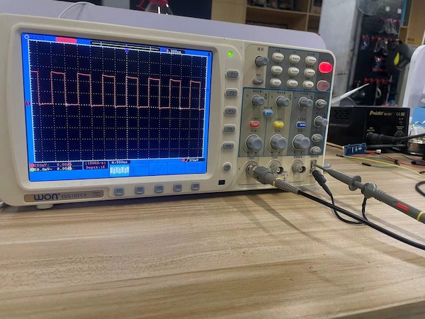
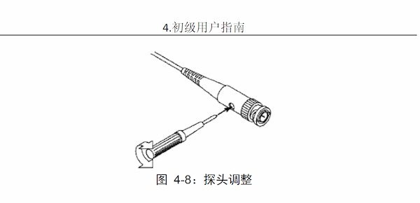
It's a matter of overcompensation.
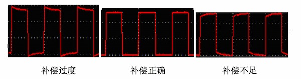
This can be adjusted by a probe:
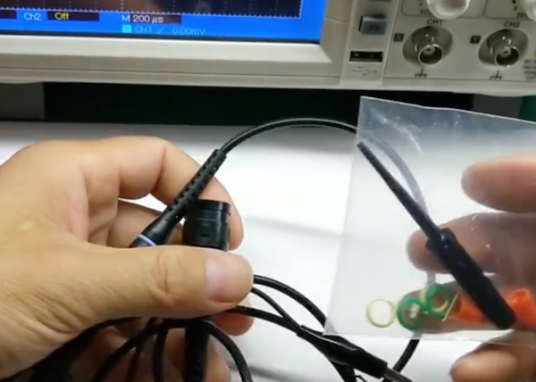
The method is looking like this:
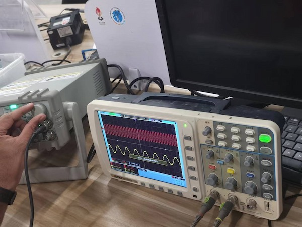
Test
Here we use one generating and the other one receiving the sine wave signal, and adjusting the frequency.
Introduction to Multimeter
A multimeter, also known as a volt-ohm-milliammeter (VOM), is an essential tool in the electronics and electrical industry. It is a handheld device used for measuring various electrical parameters such as voltage, current, and resistance. Multimeters can be analog or digital, with digital multimeters (DMMs) being more common due to their ease of use and higher accuracy.
Key Features of a Multimeter:
- Voltage Measurement: Measures both AC and DC voltages.
- Current Measurement: Capable of measuring both AC and DC currents.
- Resistance Measurement: Measures electrical resistance.
- Continuity Check: Tests if two points are electrically connected.
- Diode and Transistor Testing: Some multimeters include functionality to test diodes and transistors.
- Capacitance and Frequency Measurements: Advanced multimeters can measure capacitance and frequency.
Common Uses:
- Troubleshooting: Essential for diagnosing electrical problems in circuits.
- Maintenance: Used for routine checks to ensure electrical equipment operates correctly.
- Field Service Work: Portable nature makes it ideal for field diagnostics.
- Design and Development: Useful during the design phase of electronic circuits to measure component characteristics.
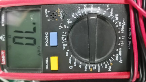
Using a Multimeter
Basic Steps to Use a Multimeter:
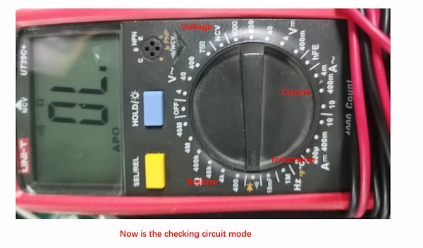
- Select the Correct Mode: Depending on what you need to measure (voltage, current, resistance), set the dial on the multimeter to the correct function.
- Connect the Probes: For most measurements, connect the black probe to the common terminal and the red probe to the appropriate terminal (voltage, ohm, or mA).
- Measurement:
- Voltage: To measure voltage, place the probes across the component or part of the circuit where you want to measure the voltage.
- Current: To measure current, the circuit must be opened, and the multimeter must be placed in series with the circuit so that the current flows through the multimeter.
- Resistance: To measure resistance, ensure the circuit power is off and place the probes across the component to measure its resistance.
- Continuity: The multimeter will emit a tone if there is continuity (i.e., a complete path) between two points.
Send the board to the Design House
I have found a design house on TaoBao and they will introduce me the workmanship doing the PCB board:
Very Professional.
Later I chose the Etching process, and it just costs about 28 yuan, for 5 pieces:

Then he showed me the images to double check with me:

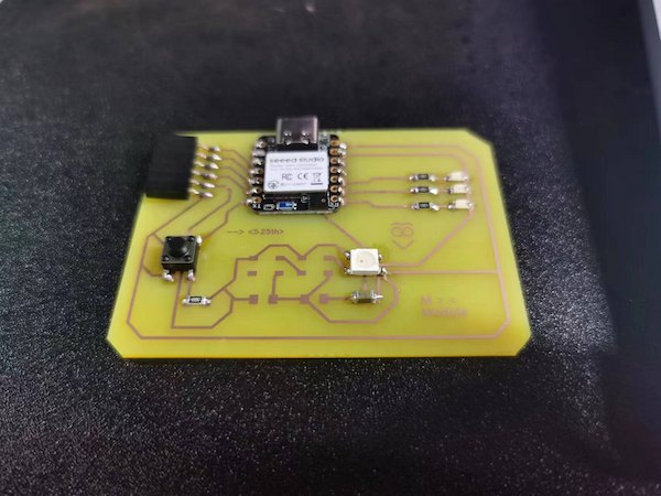
In 3/4 days, I got the boards, and use one to do the soldering:
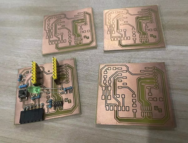
Looks really good.
And this is matthew's designed board and it is using etch technology to do it. Neat as well: