Group Assisnment Week 7 - Computer Controlled Machining
Write something at front
In this week , we are going to do lab's safety training, test runout, alignment, fixturing, speeds, feeds, materials, and toolpaths for the machine.
Safety Training
- Personal Protective Equipment (PPE):
- Wear safety glasses or face shields to protect against flying particles and sparks.
- Use heat-resistant gloves suitable for handling hot materials and operating the machine.
- Wear ear protection in environments with high noise levels.
- Ensure wearing fire-resistant clothing if welding operations are involved.
We are using the same plastic eyeglasses that we used in week4 for the protection:
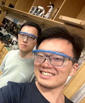
And mask for the dust inhalation
-
Emergency Procedures:
- Train all operators on the location and use of emergency stops on the machine.
- Ensure knowledge of first aid procedures for burns, cuts, and other potential injuries.
- Regularly review fire evacuation routes and procedures.
-
Machine Safety:
- Understand all machine controls and their functions.
- Never bypass any safety devices or guards on the machine.
- Ensure the machine is properly grounded, especially if welding operations are involved.
Machine Setup
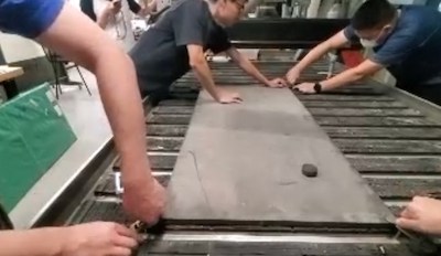
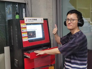
- This is the Machine we using for CNC cutting:

- Fix the board on the machine tightly, it needs to be fixed very tight otherwise the board may shift positions.
- Debugging the machine first. Uploading the test file:
- Return the machine to its mechanical origin, and manually set speed is
15000mm/minto look for zero point.
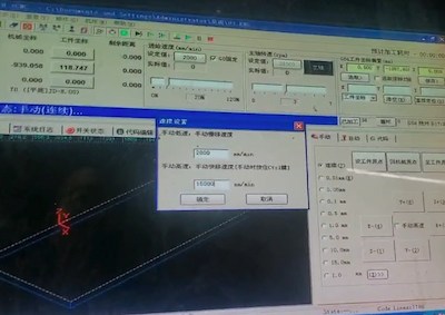
- We are using speed 5000mm/min and 8mm milling cutter to do the testing:
Calculating the tolerance is around 0.1mm and we will set it up in the software at the next step.
-
And in the lab, we are using 1.2mx2.4mx18.6mm board to do the cutting.
-
Back the machine to the zero point and everthing is setup, we can move to the G-code generation.
Operational Procedures
We are using masterCAM X6 to do the Tool Path and G-code generation.
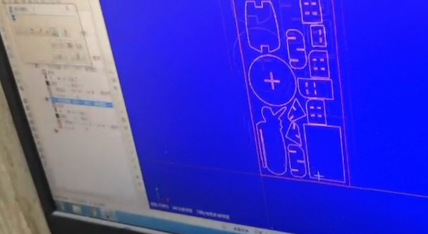
- Export the DXF files and the master who taught us CNC combined all the furniture designs of everyone using the software.
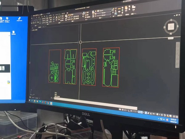
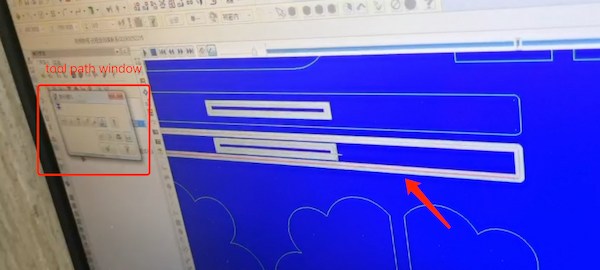
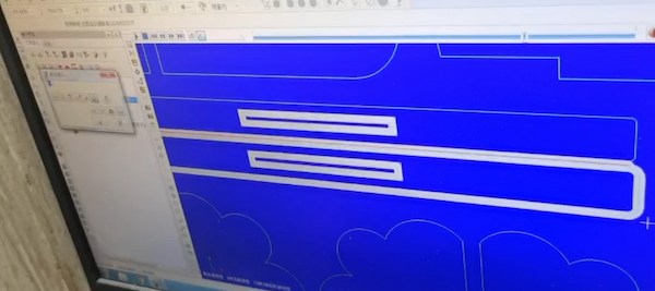
- Put everyone's dxf files on AutoCAD
The red is the size of the board of our CNC, 1200cm x 2400cm. The green is the file of the work of each member of our team.
After that, the layers need to be merged together, so setting the color can distinguish between the board and the file that needs to be cut.
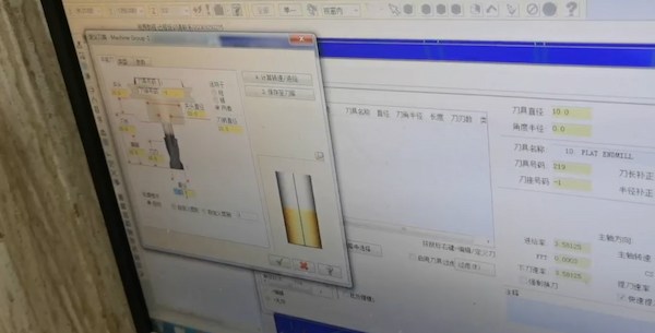
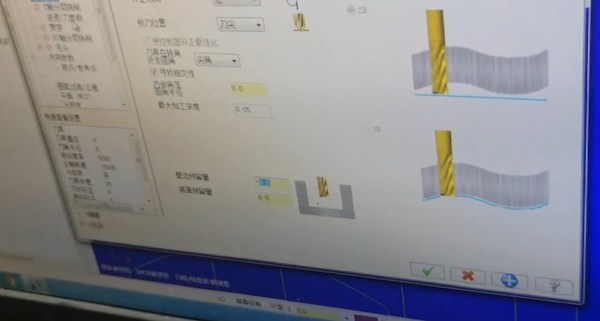
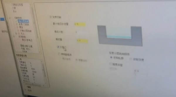
- Then create the tool, an 8mm diameter tool. Set the tool parameters as follows: rotational speed
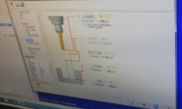
15000mm/min, feed rate5000mm/min, plunge rate500mm/min. Keep the cutting depth as default. Set the safety height to50mm, the feed plunge position to3.0, and the depth to18mm. Here are the specific ones:
Here is supposed to be 8mm(image not very clear).
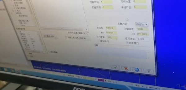
The tolerance we tested before is 0.1mm, so setting it:
- Set the safe height,
50mm- That is, after cutting, raise the Z-axis to50mm. Similarly, the thickness of the board is set here, set to18mm
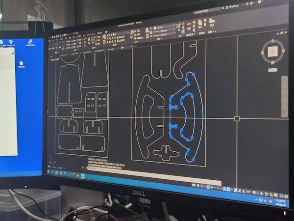
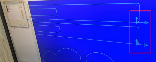
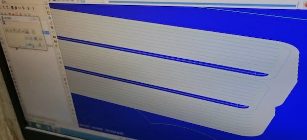
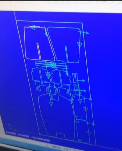
- Press "R" to view the tool path. If there's an incorrect tool direction, change its series direction.
This one is not right.
- Then keep simulating the path:
This one is right
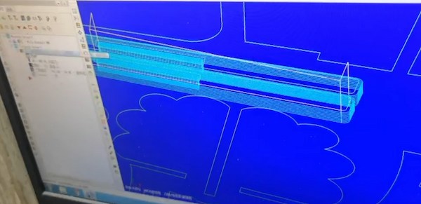
- Setting the times of milling as
2.5.
Speeds and Feeds:
- Determine the optimal cutting speeds and feeds based on the aluminum type and thickness. Aluminum generally requires higher speeds and lighter feeds.
- Use manufacturer’s guidelines or CNC software to calculate and set appropriate parameters.
- The final simulating path is:
Toolpaths:
- Design toolpaths to minimize tool wear and avoid excessive heat buildup.
- Use climb milling techniques for better finish and tool life when cutting aluminum.
- Ensure that all paths are checked in simulation software to avoid collisions and ensure efficient material removal.
- Then simulate all files:
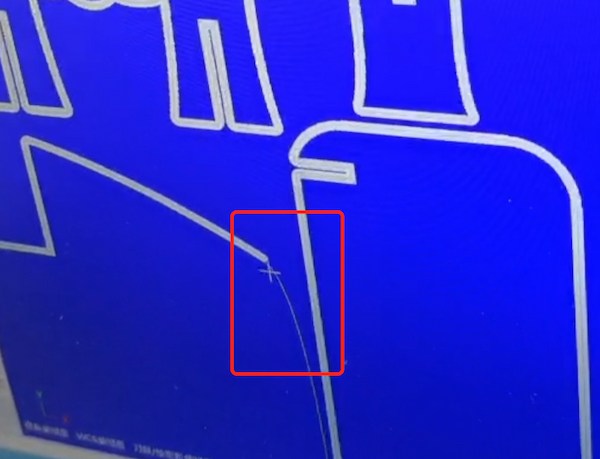
However, it will encounter a broken situation, so we need to pay attention to the exported DXF file, that is, it needs to be connected at the design time, and it may be that this curve is not recognized by the machine.
- Simulate all fine and output the G-code file
Real Cutting
We have set up the board before, hence for now, al long as we set up right the zero point, we are good to go:
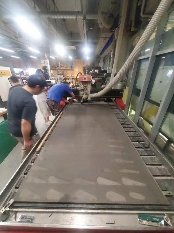
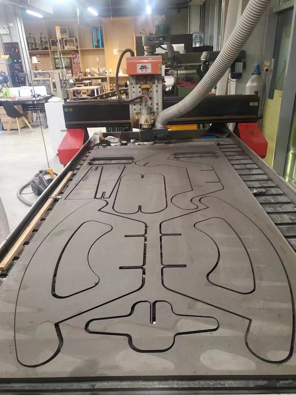
Begining the cut:
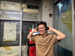
The voice is really loud, wearing a noise-cancelling headphones are a good option.
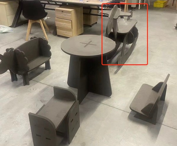
Looking really really good:
Each crew assembles its own design:
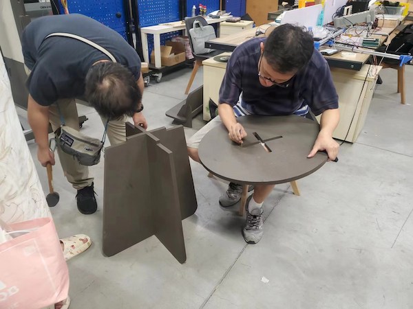
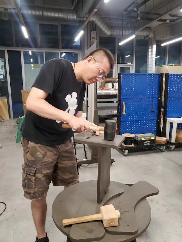
Done!!!!
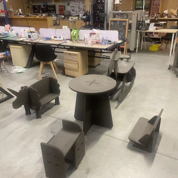
Chen Xin's baby was born! Congratulations!
Our teammember ChenXin has his second baby in July!

He is designing this rocking chair is for his kid: