Week 2: Computer Aided Design.
The assignment:
1. Evaluate and select 2D and 3D software & demonstrate and describe processes used in modelling with 2D and 3D software.
2. Model experimental objects/part of a possible project in 2D and 3D software
What is CAD? Computer Aided Design is the use of computers to assist in the creation, modification, analysis or optimization of a design.
My basic attitude is that you should go for open source software because its free (accessible for everyone), there is a community around the software for development and help and the source code is open for e.g. customization – all together a beautiful democratic mindset 😊 Proprietary software has advantages too, though, when it comes to e.g. accessible features, professional development and ease of use.
My choise is also based on my focus on how well we can integrate the software in the work that we already do in our makerspaces back home in Aarhus. I will have to take into consideration wether or not the software is accessible at my University and how steep the learningcurve will be for students and educators.
My choice of 2D and 3D software
On 2D modelling
When creating 2D models you use either vectors (lines) or pixels (dots/squares): Vectors can be enlarged limitless without loss of quality, give you smaller file sizes and can be processed on not so powerful computers. Primitive geometric shapes can be combined to represent more complex shapes and the like. Vectors are created using Vector grafik software. Useful for work with vinylcutter and lasercutter.Pixels are also called raster images or bitmaps and are the smallest unit of a bitmap. Each pixel is made of RGB sub pixels. Images pixelate when they are enlarged (loss of quality) and give you larger filesizes and might have to be compressed, especially for web use. Raster images are created with devices like cameras and scanners or with raster graphic software
On 3D modelling
Nurbs (non-uniform rational basis spline) are used to generate curves and surfaces, Uses control points to adjust surfaces, gives a smooth surface. Its accurate, takes up less space, easy transfer between software.Mesh uses reference points on the X,Y,X axes. Uses polygon modelling – easy to manipulate. Mesh polygon programs are a good starting point to learn the basics of 3D modeling. They convert directly to STL which is an advantage if you model for 3D printing.
My experiment with a part for a potential project
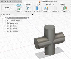
I am still thinking af making a “re-grow station”. I imagine a stand where the plants (or whatever we will be growing) can be placed and that can hold a control panel/ display with info - input and output - using a microcontroller. The stand is a simple construction with wooden round-sticks and 3D printed corner fittings.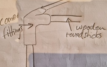
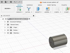
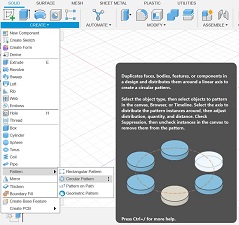
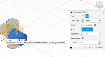
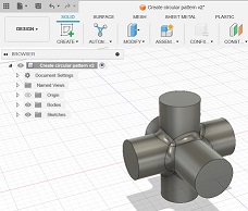
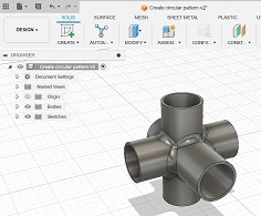
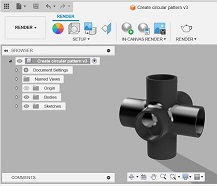
My experiment is to model a fitting using Fusion 360.
Here are the steps. (The dimensions will have to be adjusted, - this is just to see wether I can even make the fitting I imagine)