Fusion 360
Why Fusion 360
I have thought of using Fusion many times, but never gotten started. Now I have the time for it. Other reasons are:
The workflow: Fusion 360 provides an integrated platform for the entire product development process, from design to engineering, simulation, and manufacturing.
Cloudbased: Designs and project data are stored online and accessible from e.g mobile phone and it is possible to do real-time collaboration.
(Downside: Autodesk has my data on their servers – and I believe they keep them after I close my account)
Accessible: Students and educators can get free one-year educational access to Autodesk products and is renaewable as long as you are part of a University or the like.
(Downside: the first fix is free so to speak)
Some of the modelling strategies I experimented with where extrusions, fillets, grids, revolutions, sketching, parametric design, going from 2D to 3D.
See how here:
From 2D to 3D and reverse engineering(revolutions, surfaces)
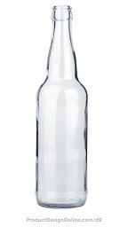
In this experiment i took a 2D image of a bottle and turned it into a 3D model. It gave me insights on features like revolutions and different surfaces of a material
 |
 |
This is how I did it:
Insert the image
1. Create a file in a folder, eg: Glasbottle
2. Create a new component for each unique part, eg bottle
3. Insert an image from the top menu (Canvas)
4. Select origin plane (front origin plane)
5. Scale and stretch the image
6. Use calibrate. Choose bottle in the browser – then canvases – right click – select calibrate tool
7. Select bottom and top and write 240 mm
Setup the reference image
8. Select origin plane and and align the bottom with the origin point.
9. Right click on the canvas and select edit canvas.
10. Use the center square to move the image
11. Align the bottom and the origin point. Click OK
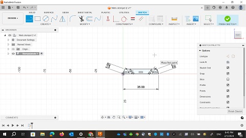
Sketch the 2D outline
12. Rightclick on the front origin plane – create sketch
13. Activate line tool from the toolbar
14. Select origin point
15. Draw a line to the top and press escape
16. Draw a new line from the origin point 30 mm to the right and draw a line of 130 mm straight up
17. Choose fit point spline to sketch the curvature of the bottle. Activtate it from the tool bar
18. Insert fit point along the neck of the bottle (as few as possible)
19. Click return when you are done
20. Create a line segment to connect the top two endpoints
21. Draw the line and make sure you have a horizontal constraint
22. After connecting the shape it has a blue background
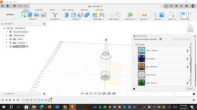
Create the 3D model
23. Activate the revolve command from the solid menu
24. The profil is automatically selected
25. select the items in the dialoque box. Select the center axis and save the revolve
26. Activate the fillet command
27. Add a 5mm rounded edge
28. Acivate the shell command
29. select the items in the dialoque box. Choose 2.5 mm for inside thickness
30. Also add a 1mm fillet to the top edegs of the bottle
31. Activate the Appearance commandAppearance command from the Modify menu
32. Search through the materials and find the glass folder
33. Save the design and you are done
I have not added a workflow discription for the next one. But for information I also did this experiment:
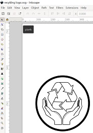
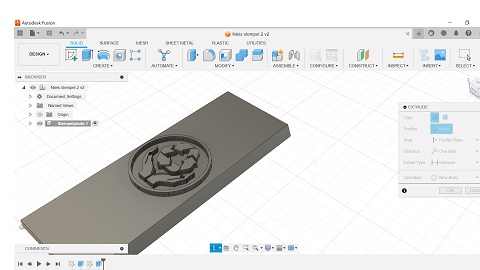
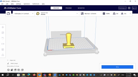
Creating a dovetail joint and inserting a SVG file in the model (Dovetail joint, inserting a SVG file, Extrude, midplane, export STL to CURA)
In this experiment I learned to make a dovetail-joint to make 2 pieces fit together. I also learned to insert a SVG file and make it a part of the model. Ilaerned about features like extrude, midplane. And in the end I tried to export the model as an *stl file to see how it would look in Cura (slicer software) for 3D printing.
 |
 |
 |
 |