Computer Controlled Machining
Assignment 7 - Fab Academy Barcelona

This week I:
CNC Stool
Overview
In class we were introduced to CNC (Computer Numerical Control) Milling. We focused on workflows using Fusion and Rhino - for my work I used Rhino with Rhino CAM. The CAM (Computer Aided Manufacturing) software translate your 2D or 3D design file into gcode; the coding that tells the machine what to do (how to mill).
Design Ideation
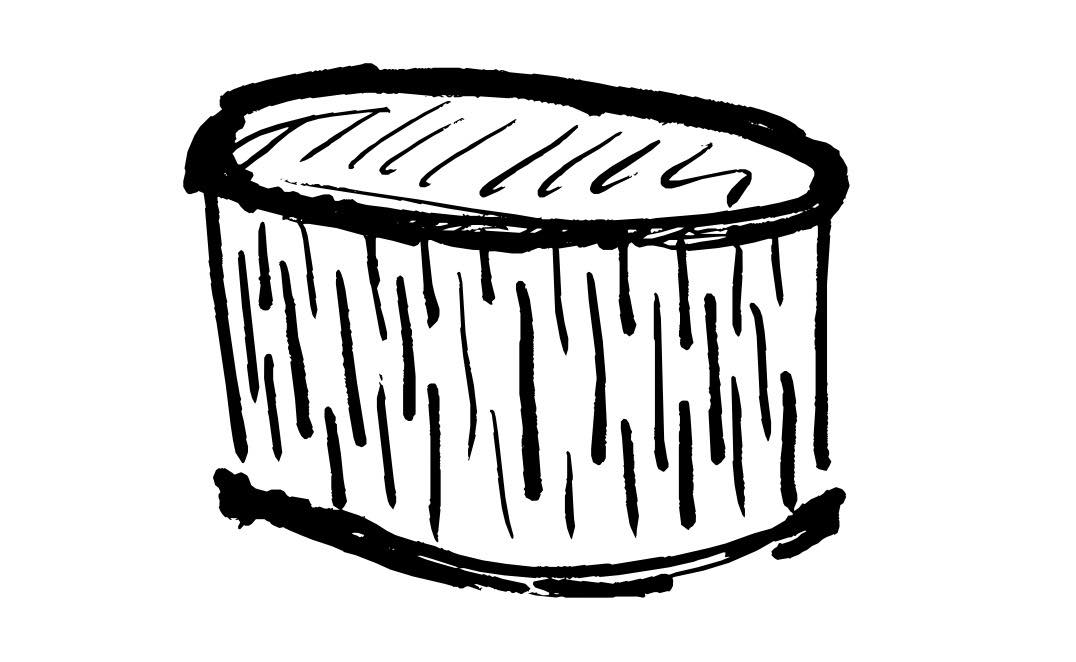
First I had to decide what to build! Our instructions were to build something big - approximately meter scale. I had three ideas: (1) a table inspired by Gaudi (given I am in Barcelona), (2) A circular stool, cutting the wood to bend so that it would curve around the outside, and (3) a waffle chair.
In the end I decided to make the stool first, given I wanted to experiment with bendable wood. However I hope to make the others over the coming months. This week inspired more creativity in me than most previous weeks - I think there is something about furniture building I connect with. Perhaps it's because I used to help my father and grandfather with this type of thing (using manual tools) when I was younger. In fact the last time I used a router was probably helping one of them nearly 30 years ago.
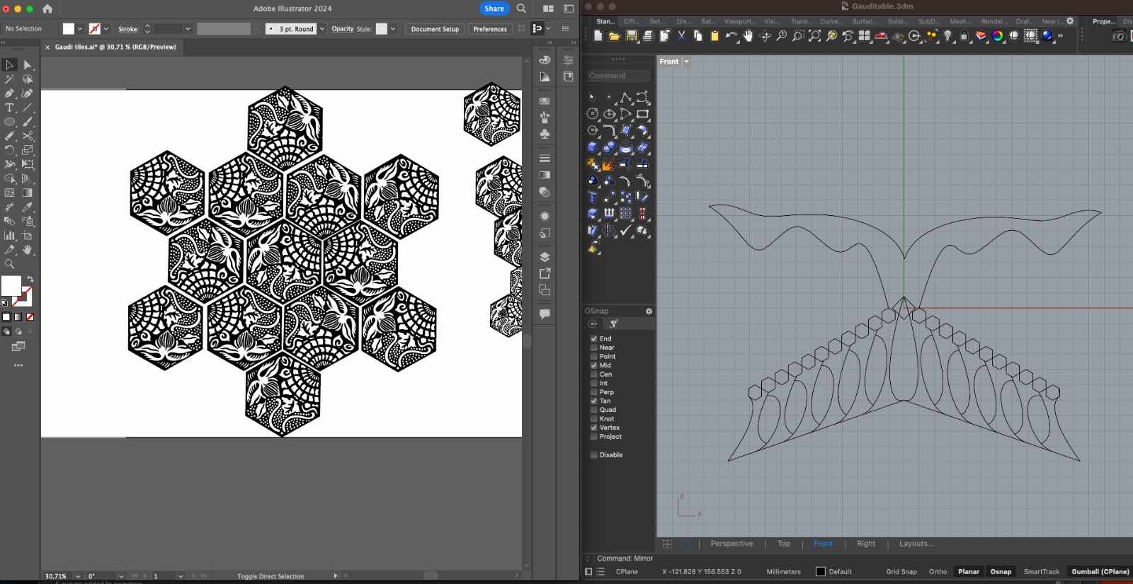
Here are early design sketches of the Gaudi table I want to build - it will have two interlocking leg pieces - the bottom is adapted from Gaudi's work over the entrance of the Sagrada Familia. I would include inlaid tiles ("panots") to form the table top. These tiles are found on the sidewalks of the city and were also designed by Gaudi. I found design files for these tiles on thingiverse. While the main structure would be cut with the CNC machine, the tiles I would cut with a laser cutter for more precision.
2D Modelling of Stool
The overall plan was to create a round stool with a single panel of bendable wood going around the outside.
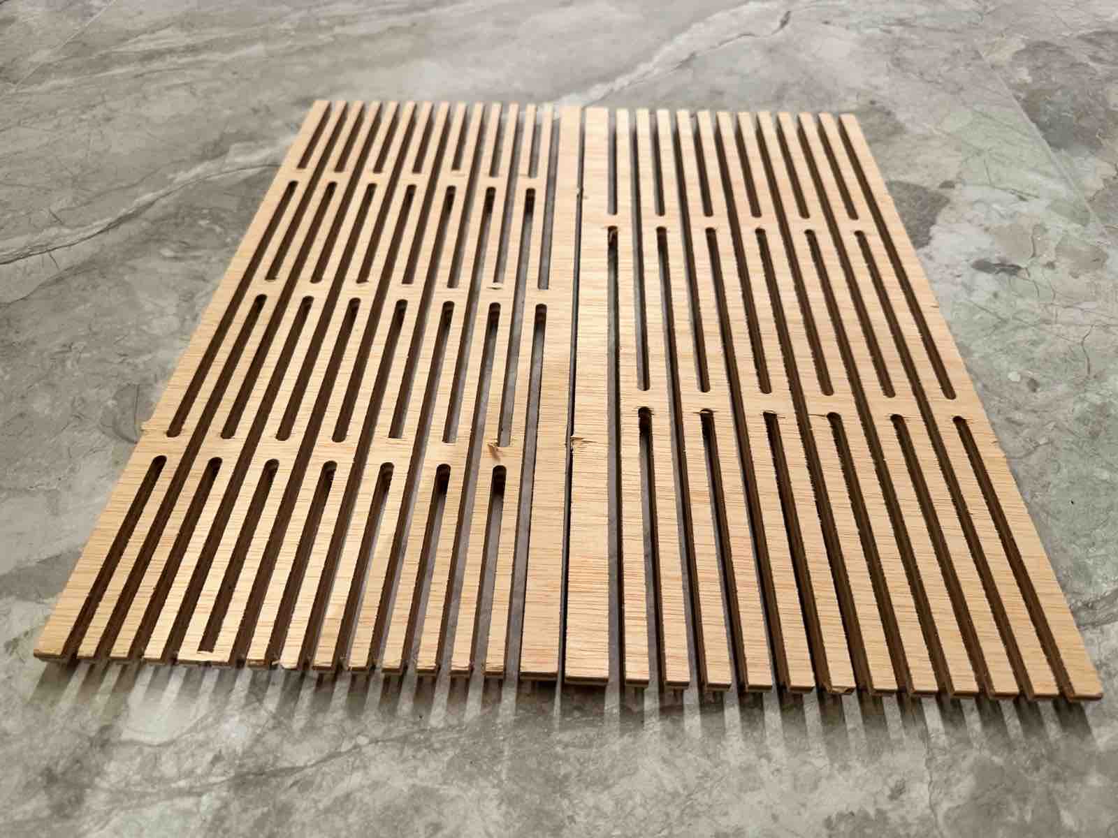
I started by milling a small panel using the "living hinge" file provided in class. However this did no bend at all. I needed fewer "hinges" per unit length of w. I also tested curved "sockets" for the ends of the side panel to fit on. These did not work given I forgot to add dog bones, and because the panel did not bend to fit.
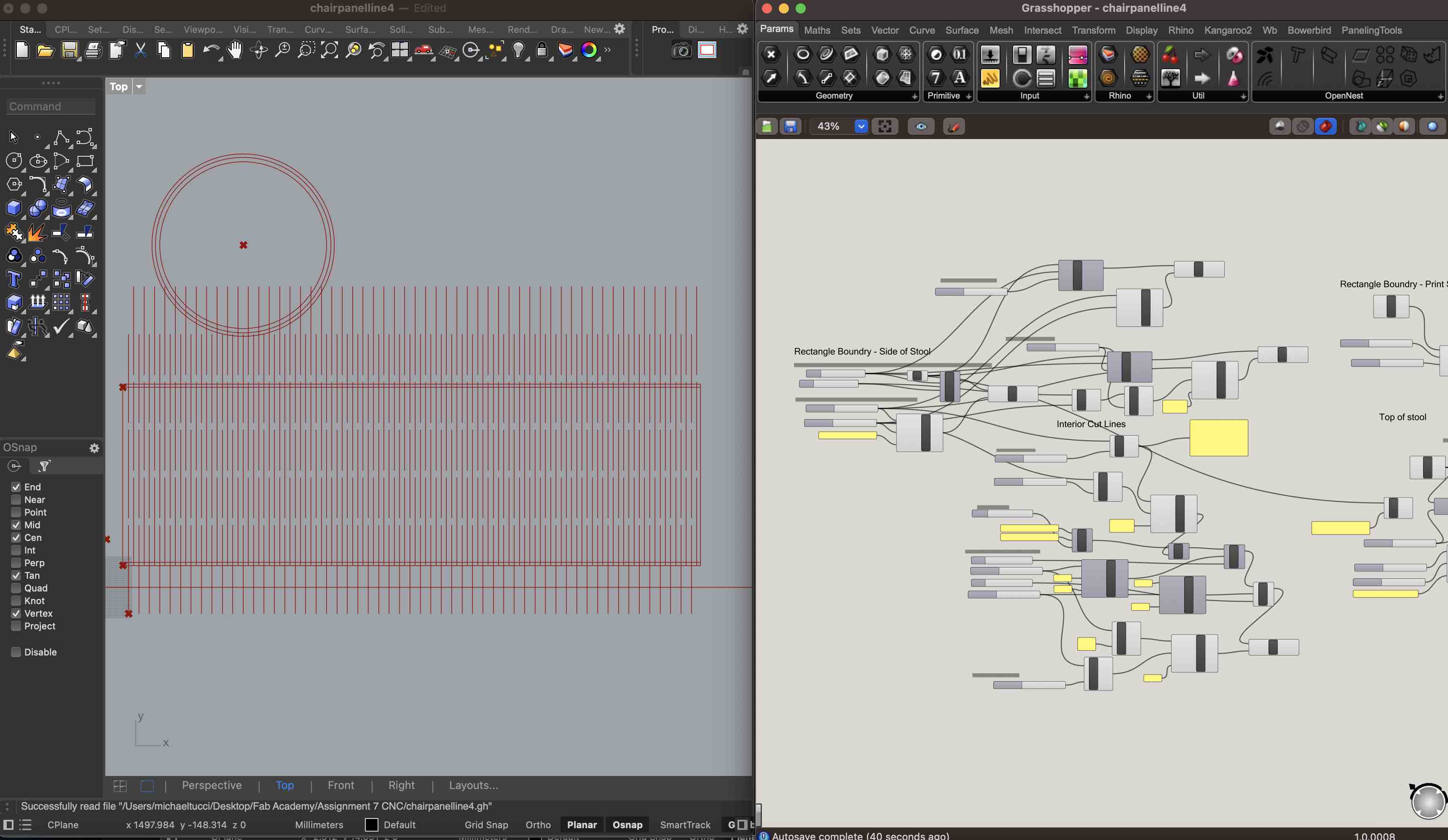
I created a full size model in grasshopper from scratch (no longer "living hinge" template). This was to have more control AND to make the grasshopper file lighter. There are components to control the size of the print board / wood for printing, the size of the
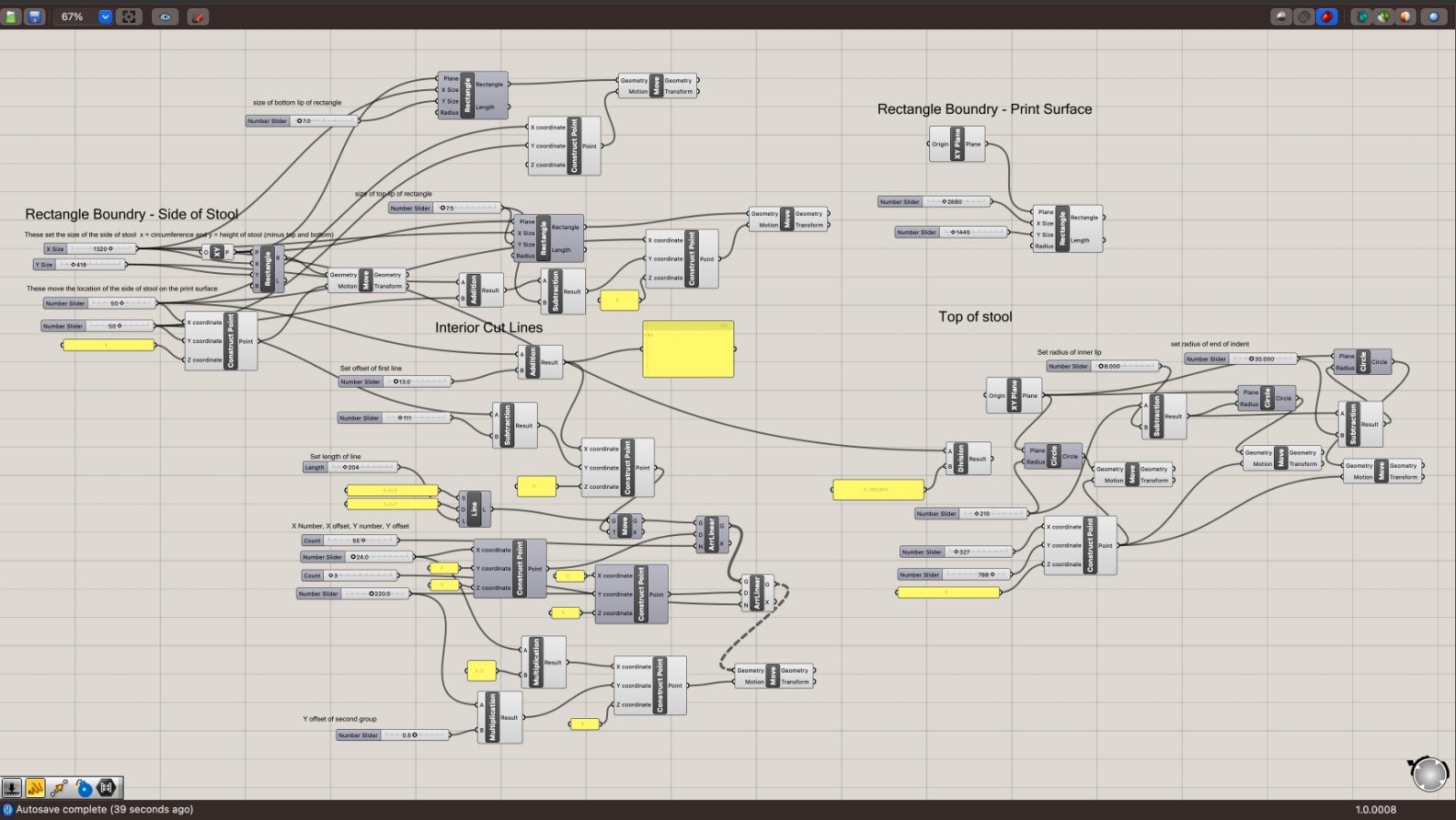
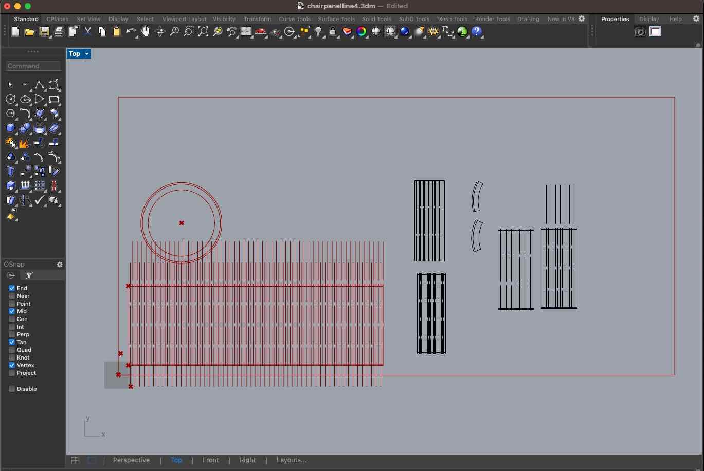
I then tested two panels at full height - one included 3 hinges and one included 4 hinges. I also tested a circular top with lip to hold the curved surface in place. See additional details on these tests below. The test panels are baked to the right in screenshot below.
Mill File Prep
I prepped my Mill file in RhinoCAM using the workflow we reviewed in class (HTML of list created with help of ChatGPT):
RhinoCam
- Select Machine - 3 axis CNC_STEP_BCN
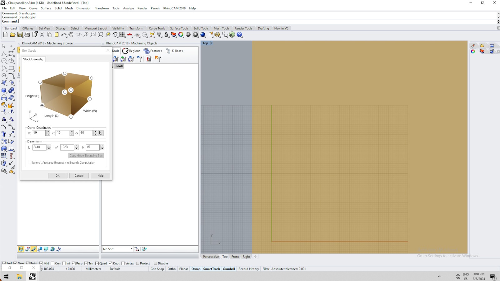
- Box Stock:
- Stock Geometry: origin in the top left bottom corner
- Corner coordinates: 0, 0, 0
- Dimensions: L, W, H (2440,1220,15)
- Screw material and then around the area you want to cut.
- Draw points in Rhino where you have located your screws
- Go to Machining operations - 2 axis
- Roughing
- Pocketing (emptying part of the material)
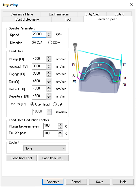
- Engraving (on cut) (choose it for making the "screws" spot and then select the points where you want to make the mark)
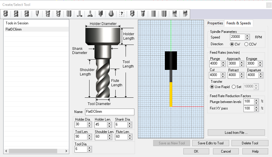
- Create/Select Tool
- Fablab just have bold and flat mills.
- For the screws choose flat (next parameters should be according to the one you are going to use)
- Name it - I used Flat DC 6mm Mill
- Holder Dia: 30
- Holder Len: 45
- Shank Dia: 6
- Tool Len: 90
- Shoulder Len: 60
- Flute Len: 60
- Tool Dia: 6
- Flute: 1
- Spindle Parameters: Speed: 18000 RPM, Direction: CW, Cut (calculate with cheapload equation): 4500, Retract: same as Cut, Departure: same as Cut. Plunge ("half of cut"): 2000, Approach: same as plunge and Engage: same as plunge.
- Clearance Plane: Clearance Plane Definition: Part Max Z + Dist: 20 (Never Automatic)
- Cut Parameters: we only care about "Cut Depth Control": 3mm
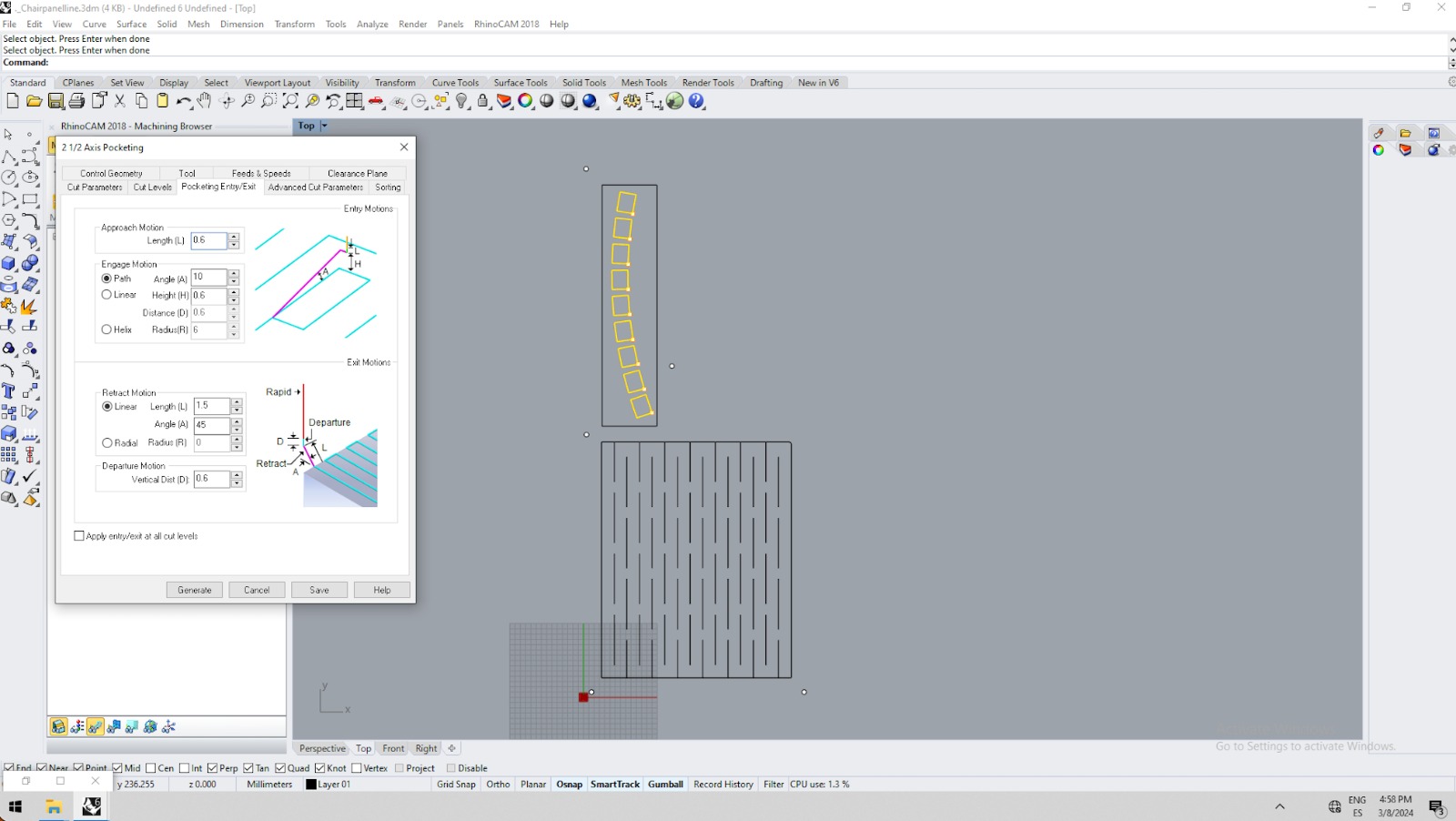
- Entry/Exit:
- Sorting: Minimum Distance Sort
- For pocketing:
- Feeds and Speeds: 20000 RPM
- Clearance Plane: Clearance Plane Definition: Part Max Z + Dist: 20 (Never Automatic)
- Global Parameters: Climb
- Cut Patter: Offset
- Etc.
- For profiling/outside: use along path! when using profiling the machine doesn't recognize other pieces. So we'd like to use along path so it can slide and approach directly to the selected piece. Remember to add taps (bridges).
- For the screws choose flat (next parameters should be according to the one you are going to use)
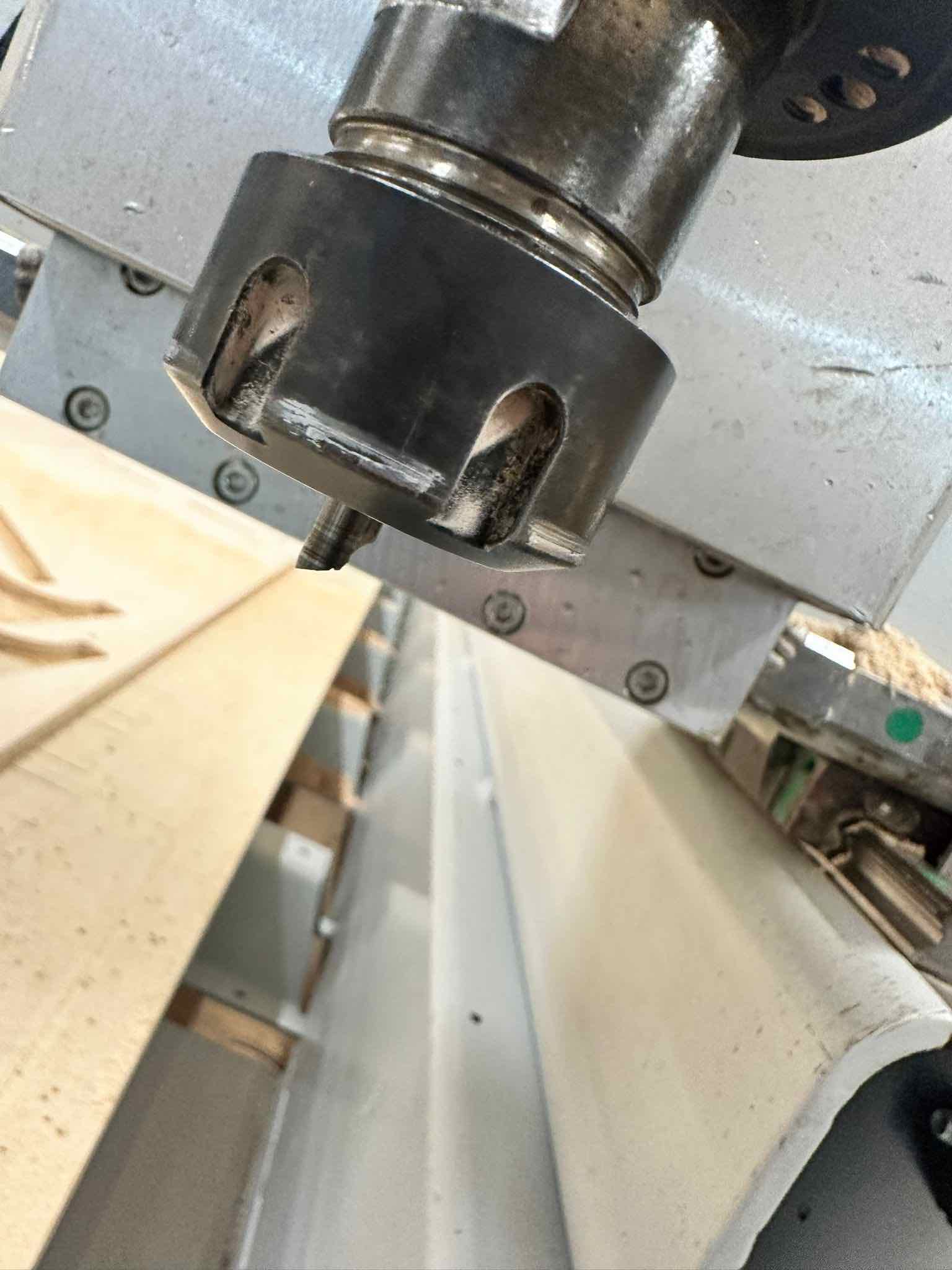
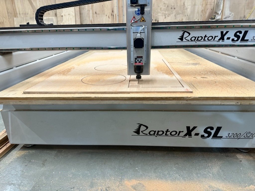
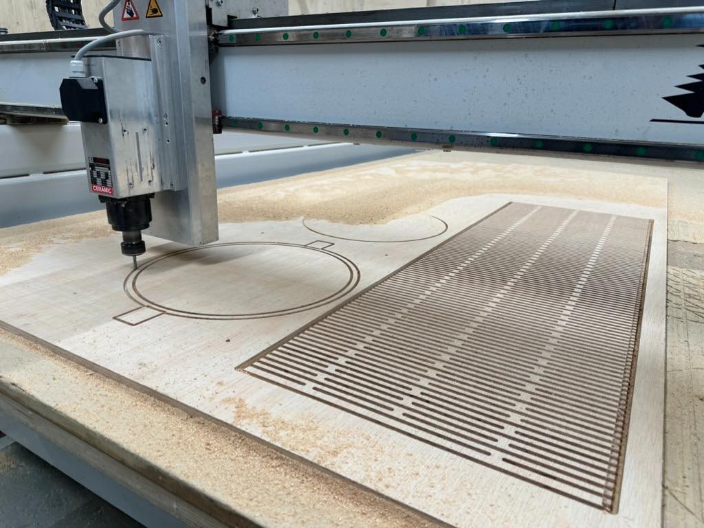
Milling (aka I break everything)
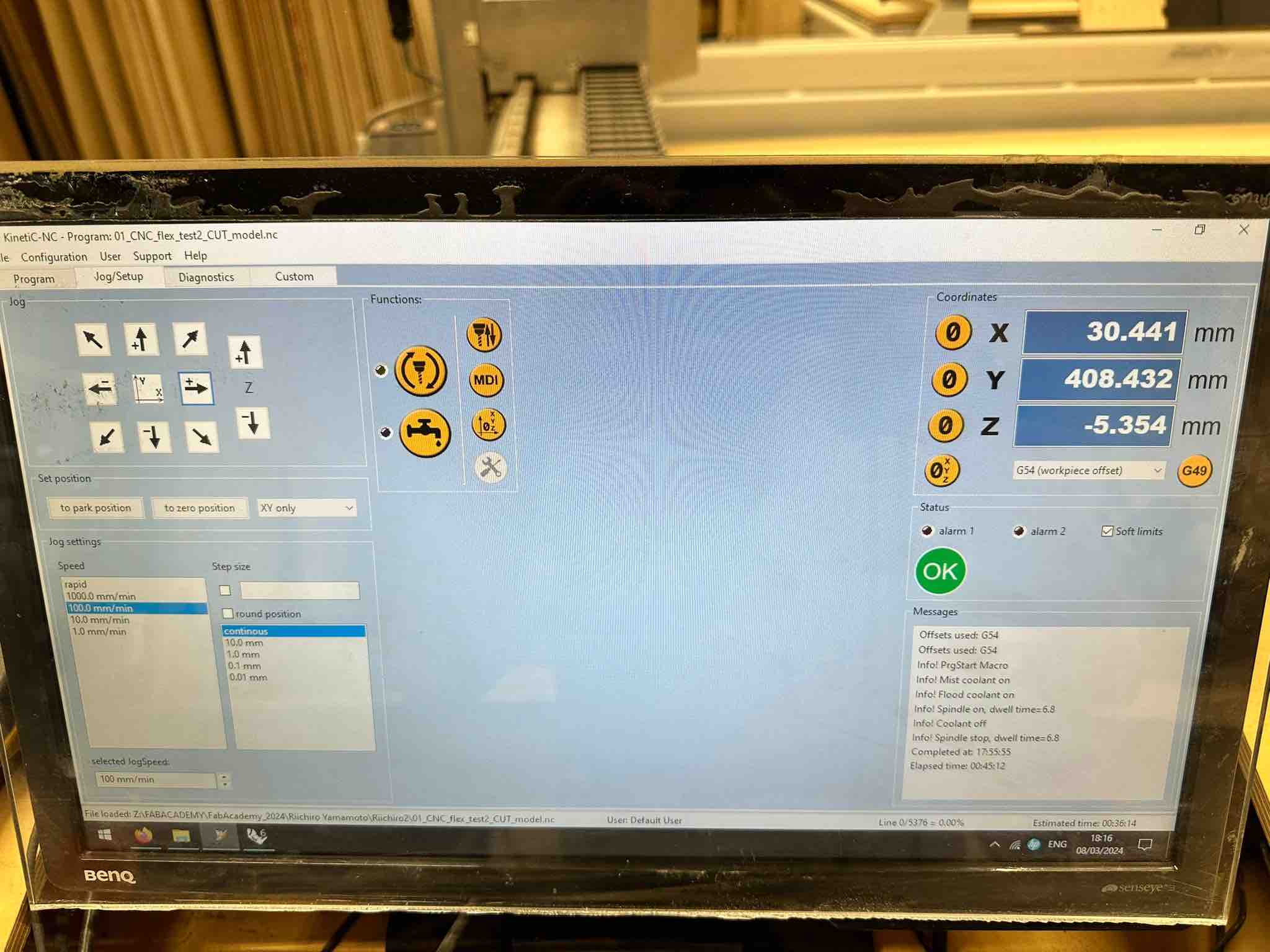
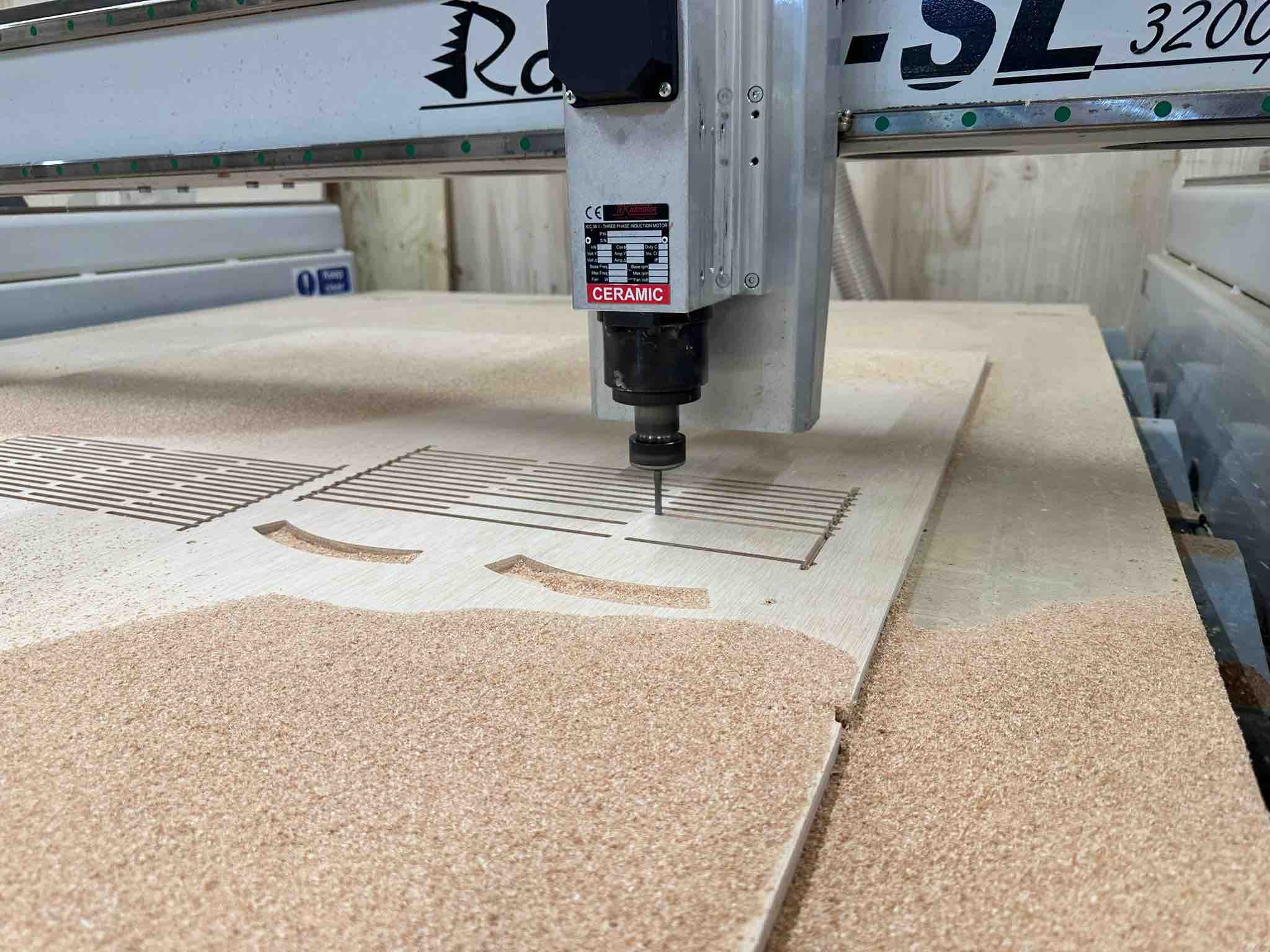
Once the CAM files were prepared I put on a thumb drive and brought to our Raptor XL CNC machine. I then zeroed the X, Y, and Z of the machine.
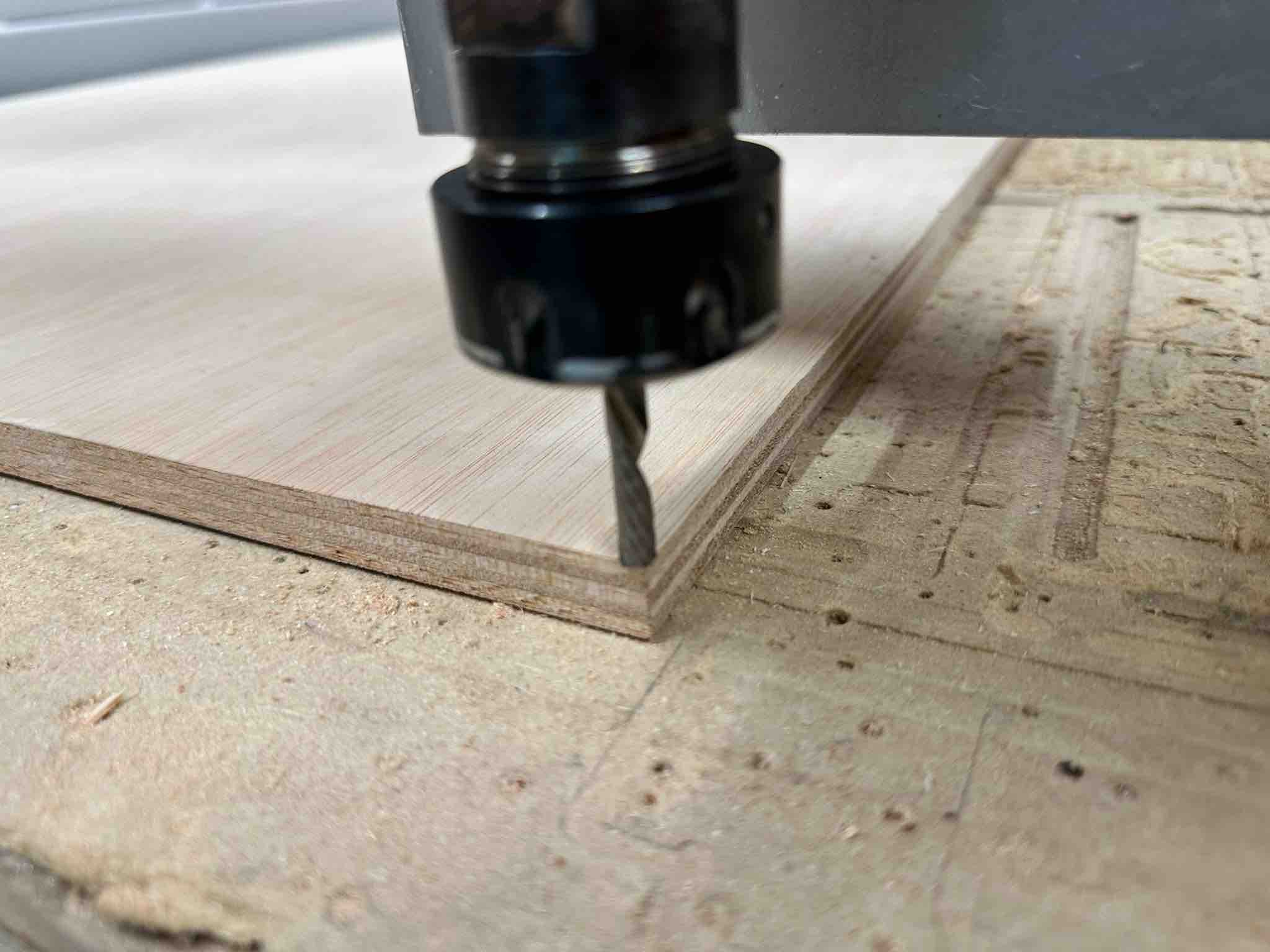
I started with the drill hole file. This drilled pilot holes where I would place my screws. I then stopped the machine and screwed my board into the sacrificial CNC bed to secure it.
I then loaded and ran the files for pocketing (indented surfaces like the top lip), engraving (lines) and outlines. On my second test, I broke the mill bit when running the engraving file. I accidentally selected the drill points when selecting curves for my engraving file, and the mill came down right on top of one of the screws and immediately snapped. I felt like an idiot, especially given how many times I had checked and rechecked the file (both on my own and with teachers). But I (hopefully) learned my lesson!
Testing
As mentioned above I first ran a test with a hinge panel that didn't bend. The key learnings from this initial test were (1) need more hinges per unit length and (2) no need for individual pockets in lid/bottom, can simply use lip.
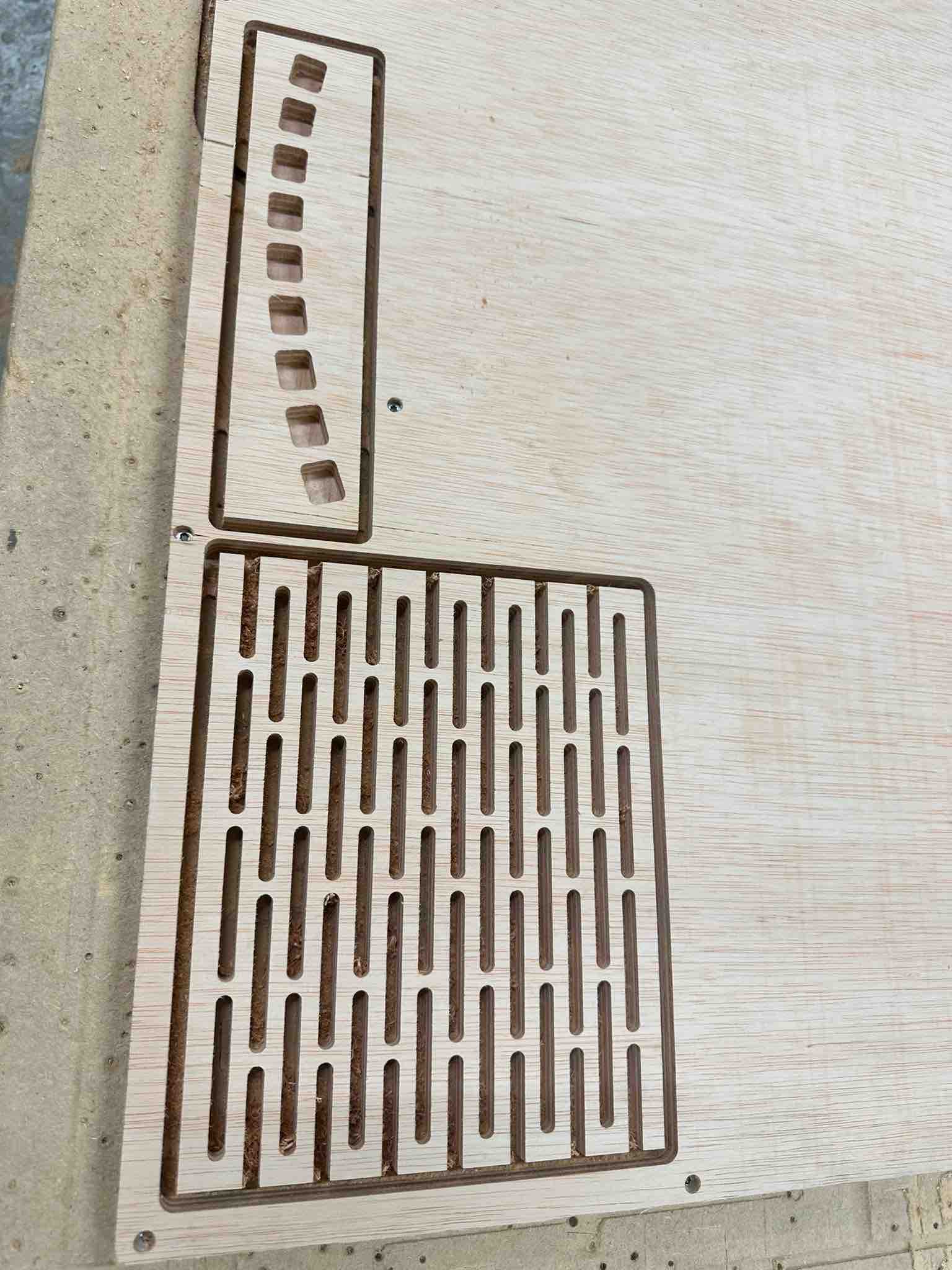
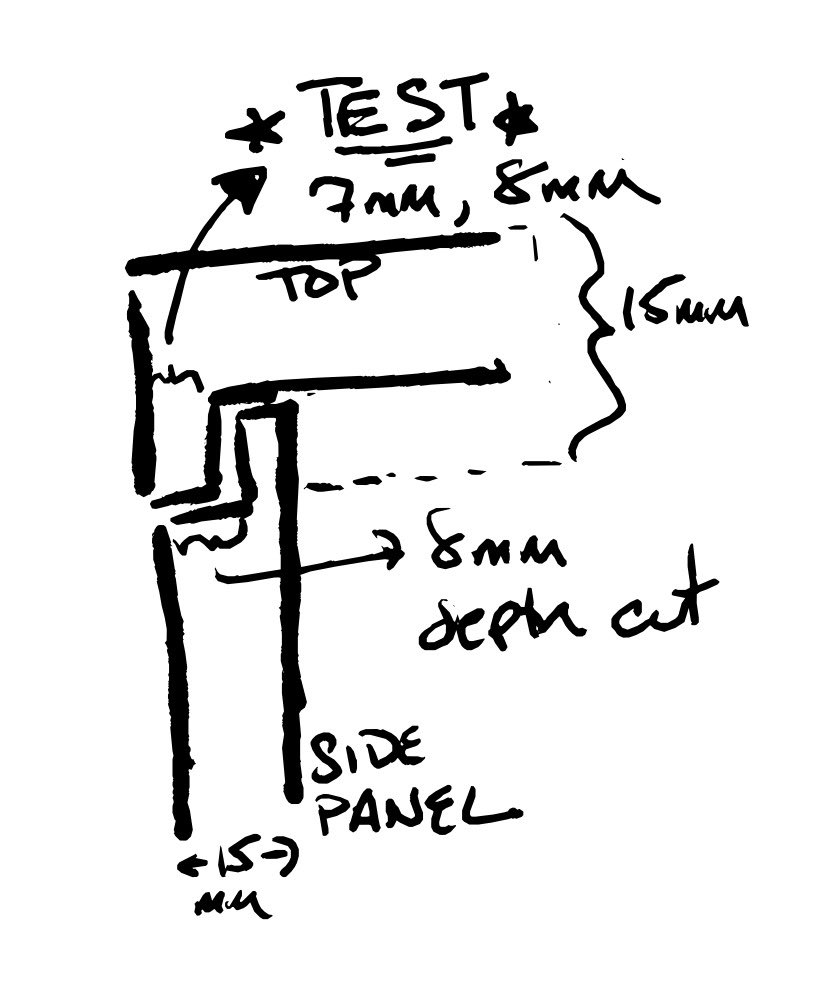
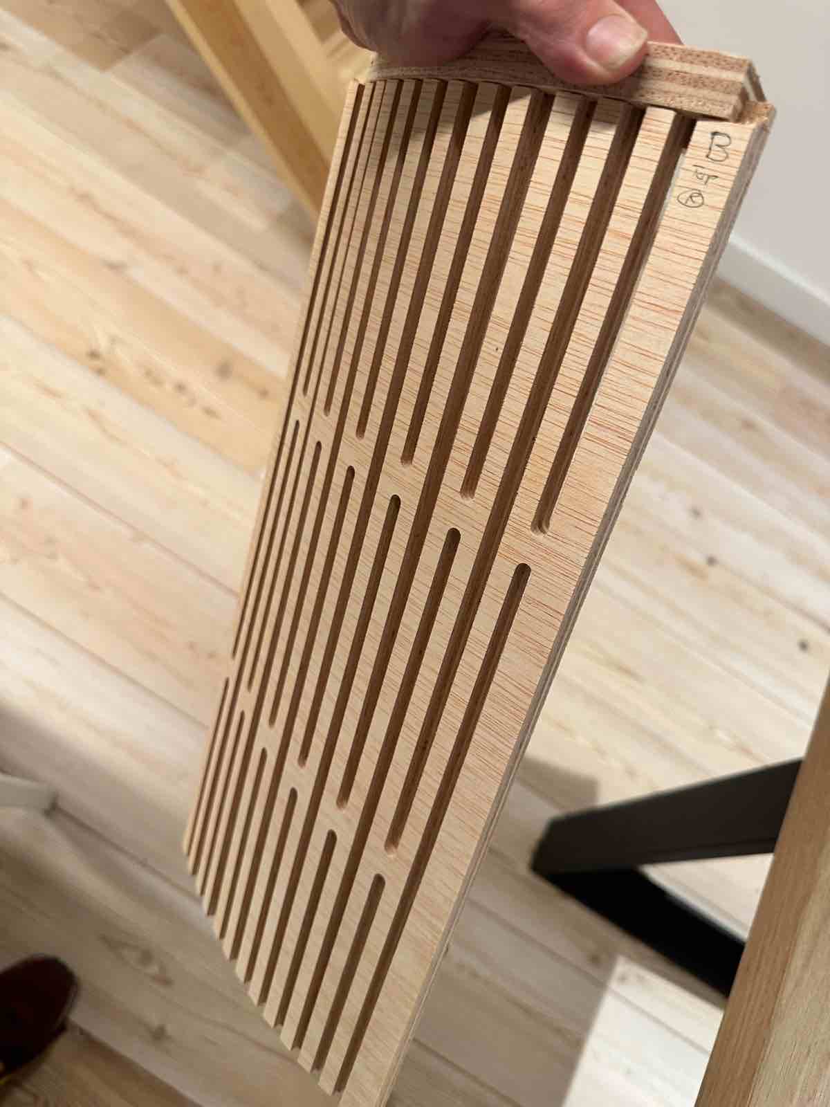
I then cut test panels with full height to see if they would bend and to test sizing for lip of lid of stool. The outer panels are designed to have a recess at the top and the bottom that will fit up against a lip around the circular top and bottom of the stool.
Lid Lip Test. For the top/bottom I tested a lip of 7mm and 8mm, while cutting an indent (depth) in the side panel of 8mm. I found that the top lip of 8mm worked better than 7mm. It will provide room to sand down edges of top while still starting with a relatively flush surface. I also decided that the top and bottom will need a interior lip as well - to be measured but like also 7-8mm.
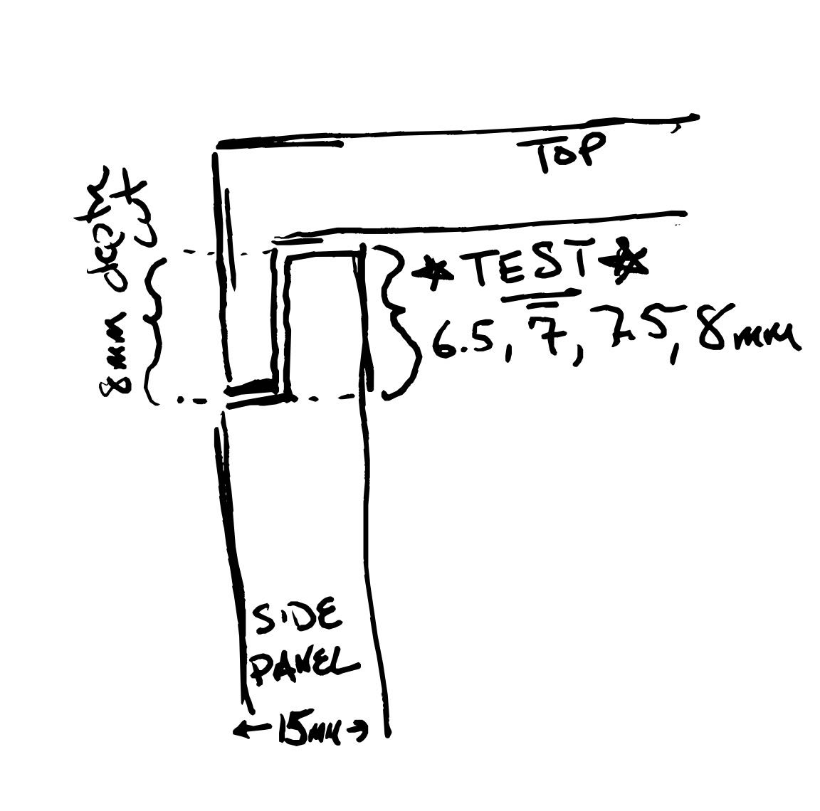
Panel Recess Test. For the sides I tested a top and bottom recess cut at a depth of 8mm, and found that 7.5mm provided the best fit against the top and bottom (I tested lengths of 6.5, 7, 7.5, and 8mm).
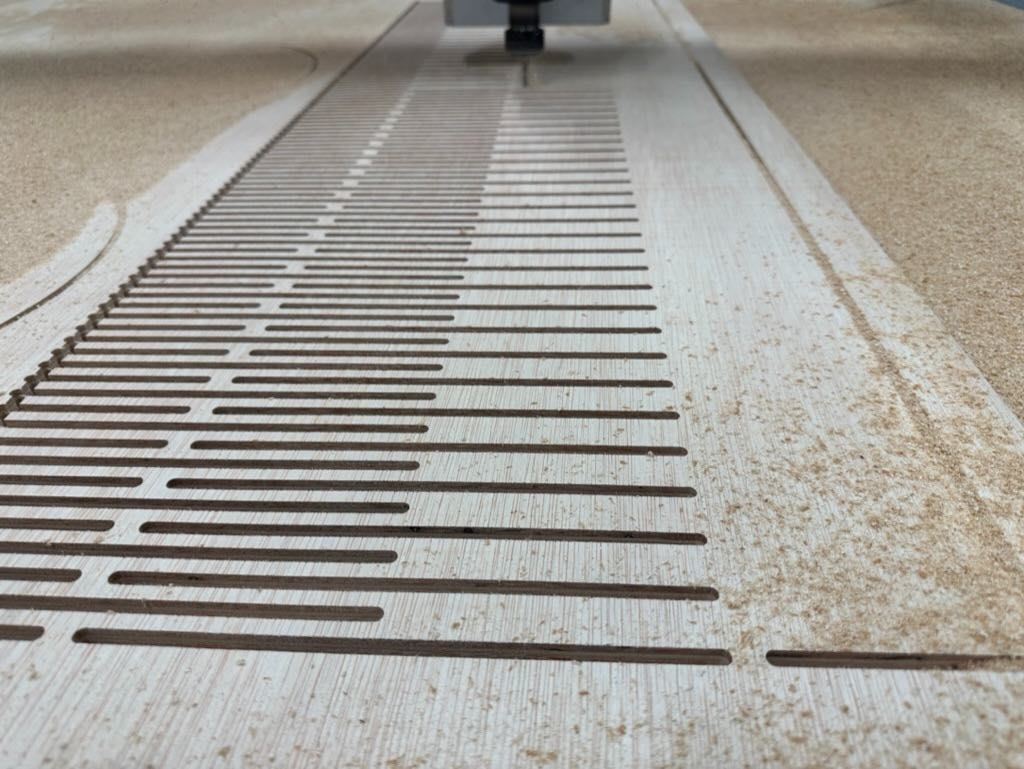
In the end both panels bent easily, though the panel with 3 hinges was substantially sturdier. I also liked the aesthetics more.
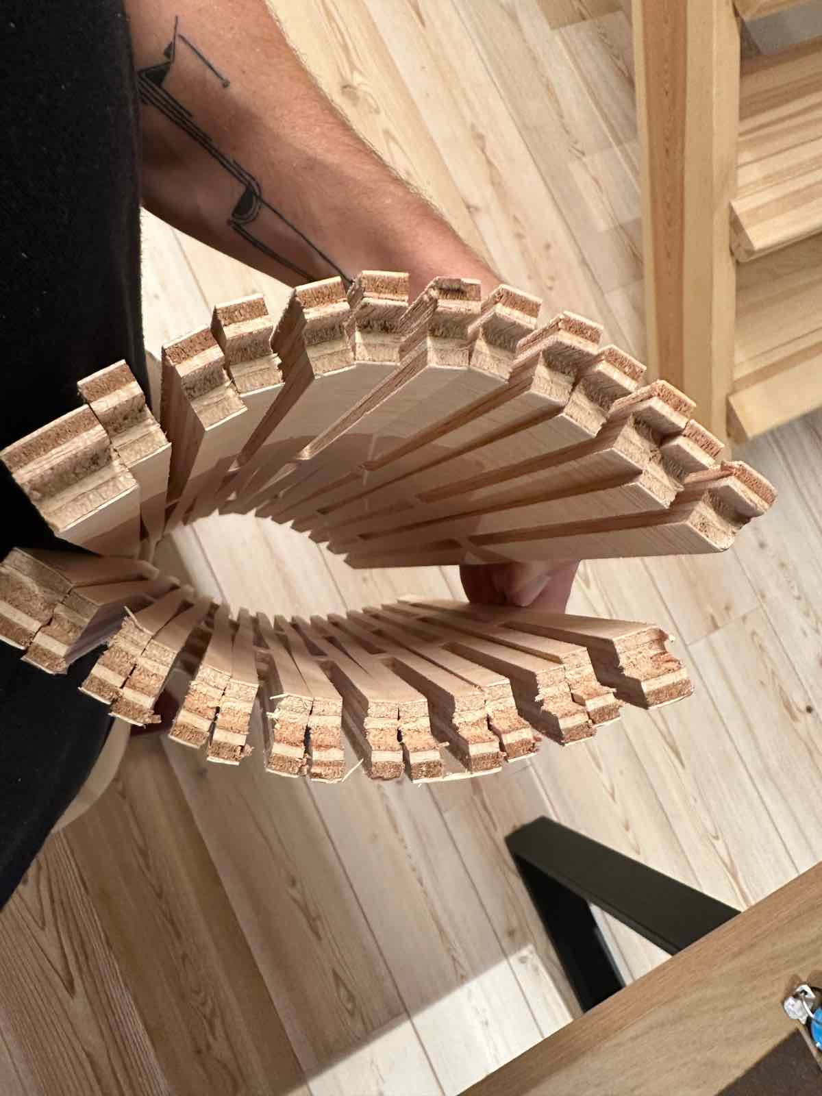
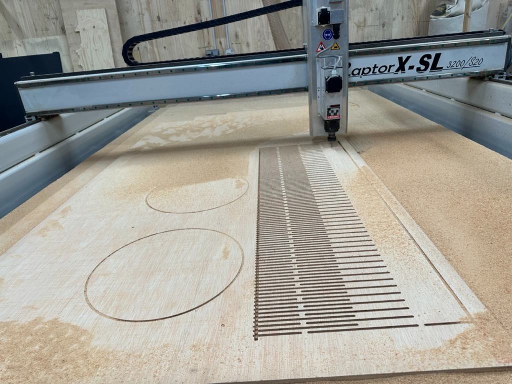
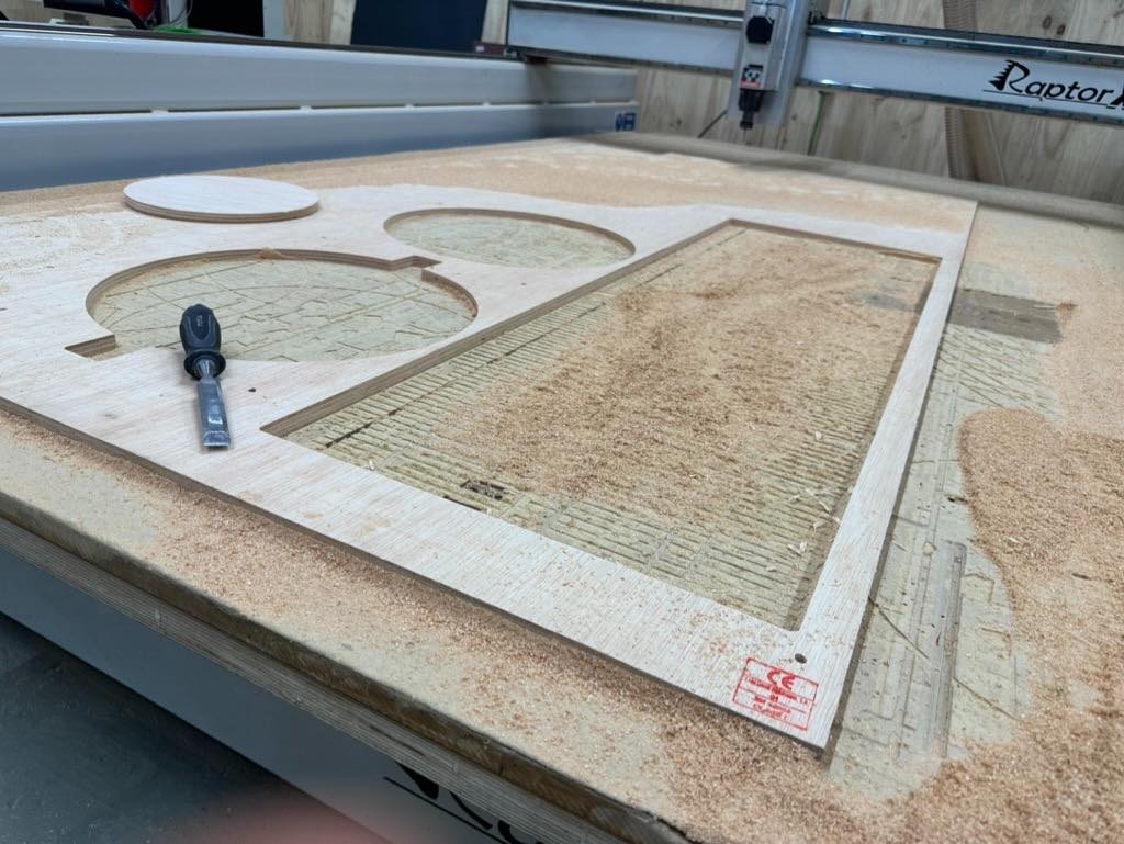
Final Cutting
With the tests completed I prepared and cut the final files on the Raptor. This consisted of one long continuous bendable panel for the outside and two circles for the top and the bottom.
FINAL DESIGN FILE SCREENSHOTS
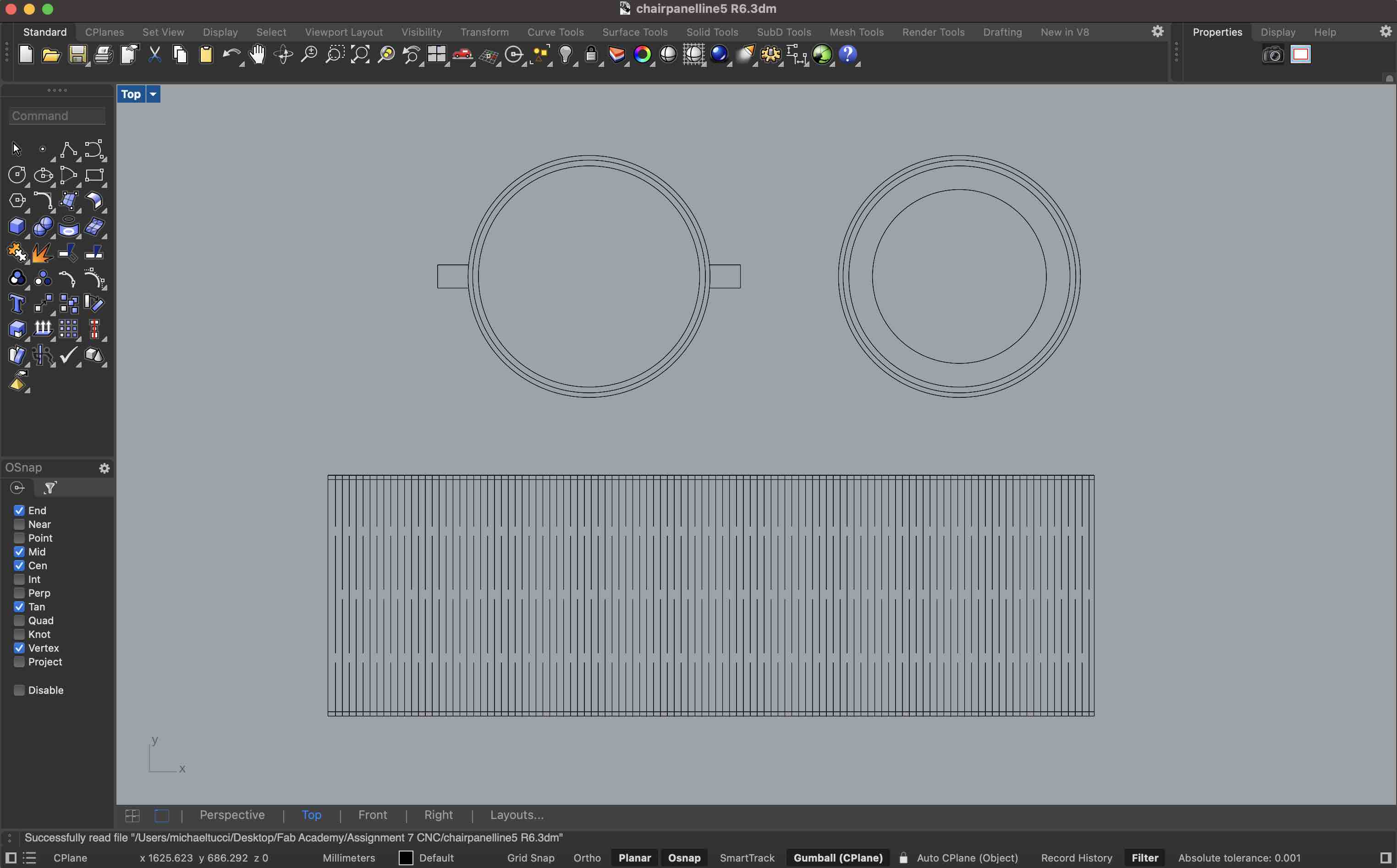
CUTTING
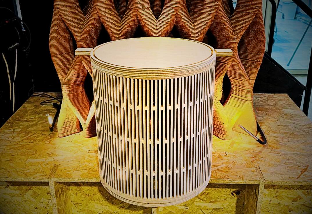
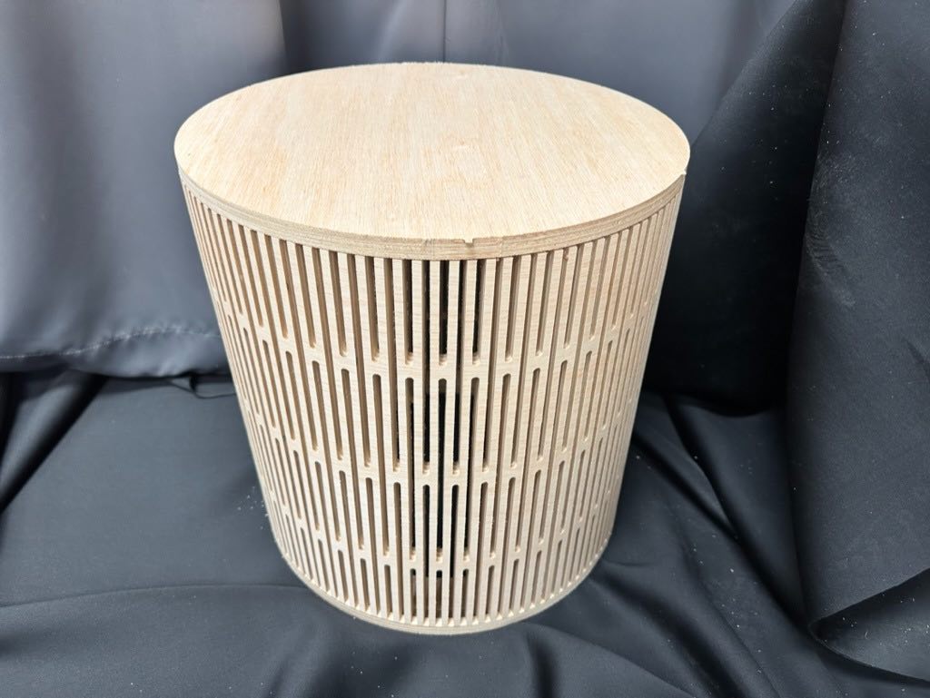
Assembly
I then assembled the final table by fitting the top/bottom edge of the panel into the groove milled into the top and bottom circular panels. In the end the dimensions made it a bit more appropriate as a side table than a stool.
Design Files
Group CNC Work
The full write-up of the group work can be found here.
As a group we reviewed safety procedures for CNC machines - most importantly wearing PPE (goggles) and understanding how to operate and stop the machine correctly. We also reviewed the workflow together and created and milled test files/cuts in Fusion and RhinoCAM. This was a useful introduction but (as usual) I really needed to work through the end-to-end process myself to understand and fully integrate machine operation. I found this workflow to be the most complex yet. However I also found it the most gratifying and enjoyable.