
Week 18: Project Development
This week was all about tracking our final project process. Here is a link to follow.
Concept
My final project idea has changed throughout the Fab Lab and thinking about and (attempting) to model something for the CNC, which ultimately failed, helped me to relieve some pressure and evolve the final project concept in favor of developing a smaller, workeable prototype.
While the idea of working with sound has not changed from the beginning of my time at Fab Lab, I am focusing on developing a synthesizer more in line with work I have been doing in my own creative practice. I intend to keep my original idea of a larger format sound altar and run with it at a later date - it's something I will produce in the future.
Inspiration
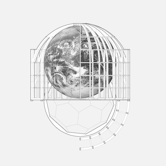
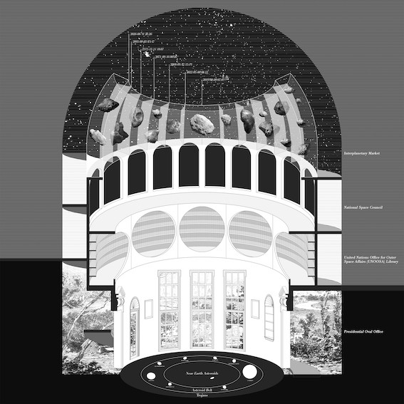
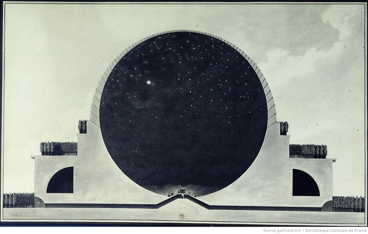
I've been revisiting Design Earth's Blue Marble Circus and Cosmorama projects as references for this work. These projects and the one I'm developing all lead back to Etienne Louis Boullee's visionary architecture, specifically Newton's Cenotaph:
I have been really drawn to and curious about creating more conceptual/sculptural pieces for technology, so I'm taking the opportunity of Fab Academy to do so.
Sketches and Design Trials
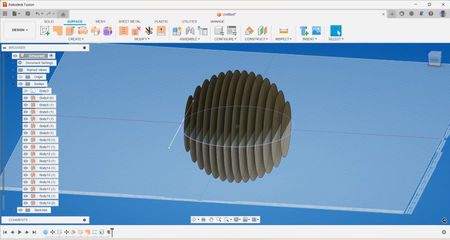
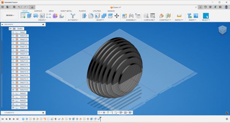
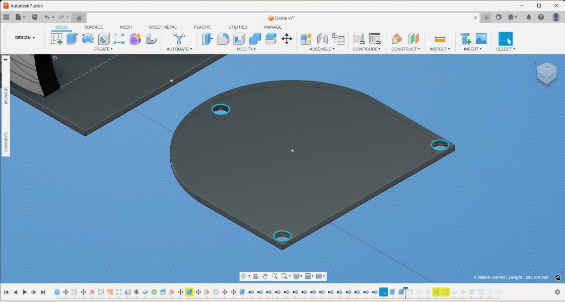
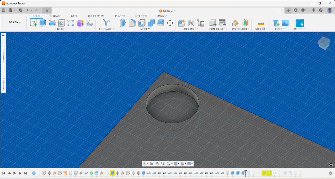
Dome
Different modeling explorations for the dome shape got me to the point I am in now, which is considering slicing and stacking for laser/CNC cuts:
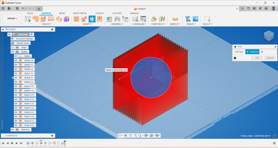
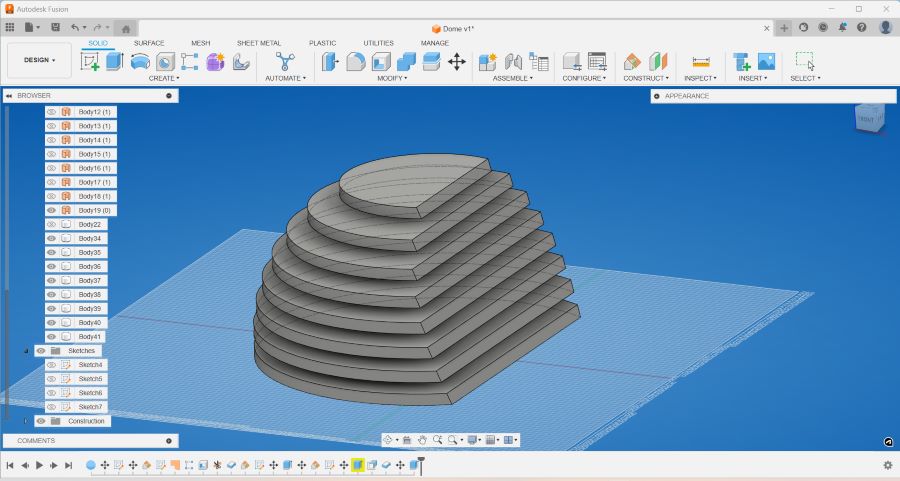
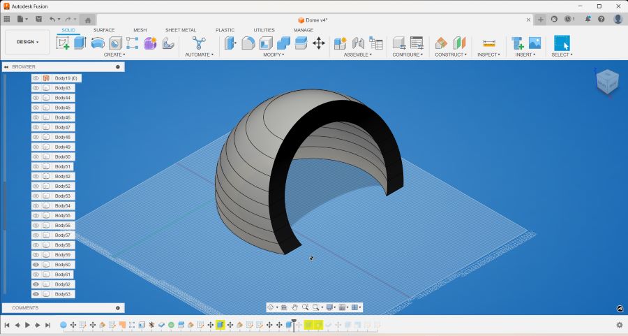
I am considering the thickiness of my material and also what method of joining these layers together I should use. This dome is intended to serve as a sound amplification shape, and my conclusion is that I can produce the dome if I have enough time. My reason is that I'd rather prioritize the rest of the components which need more attention and development.
I think simplifying the structure and taking focus off from creating my dome shape for the sake of efficiency is best right now.
Speakers
I wanted to make a reference back to computer controlled cutting week and continue working with a maze design. I was able to output a maze by using a maze generator online and vinyl cut the design on textile, so I wanted to rework a maze design for my final project to function as a speaker grill.
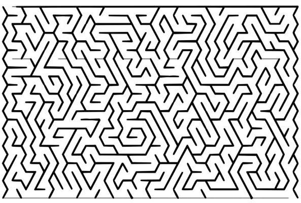
There are different sites where you can generate mazes according to desired parameters and settings:
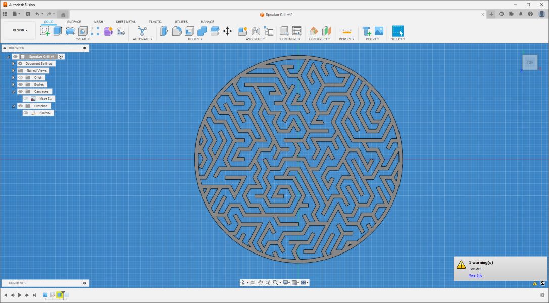
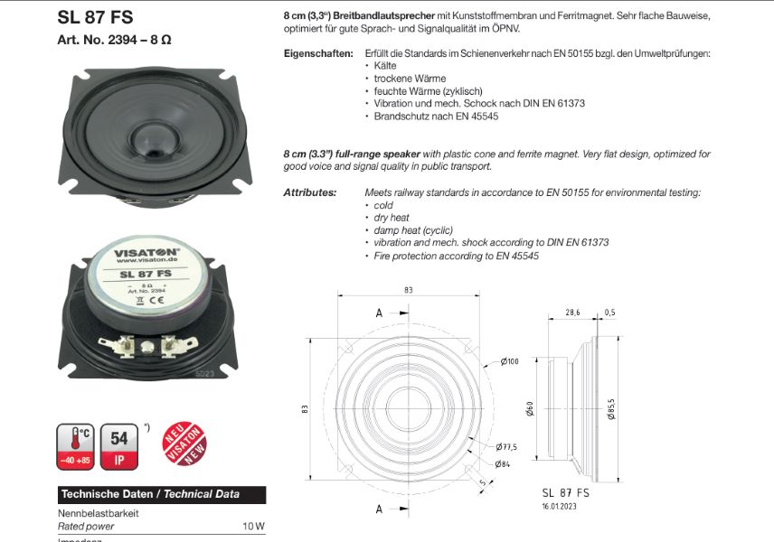
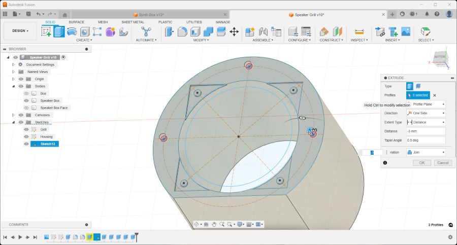
Once I generated my maze, I was able to customize and refine it in Fusion 360. I started by inserting the maze image into my Fusion 360 sketch to trace it, following my speaker specifications.
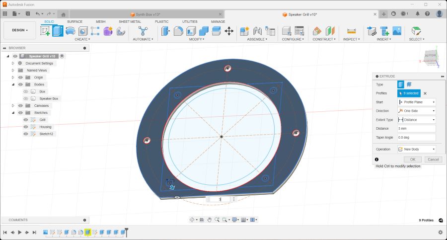
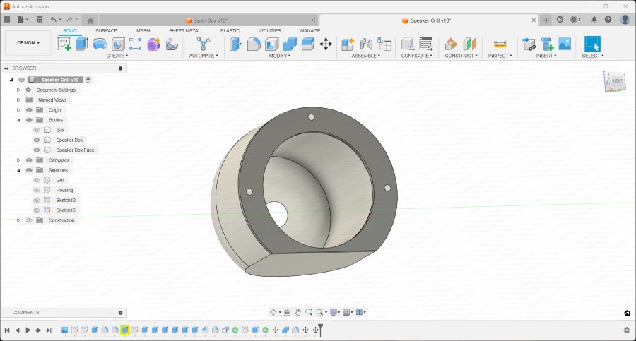
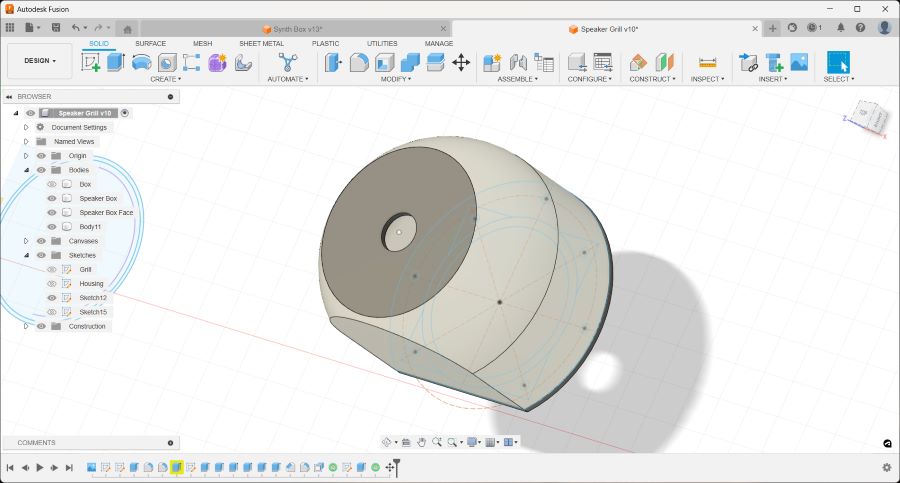
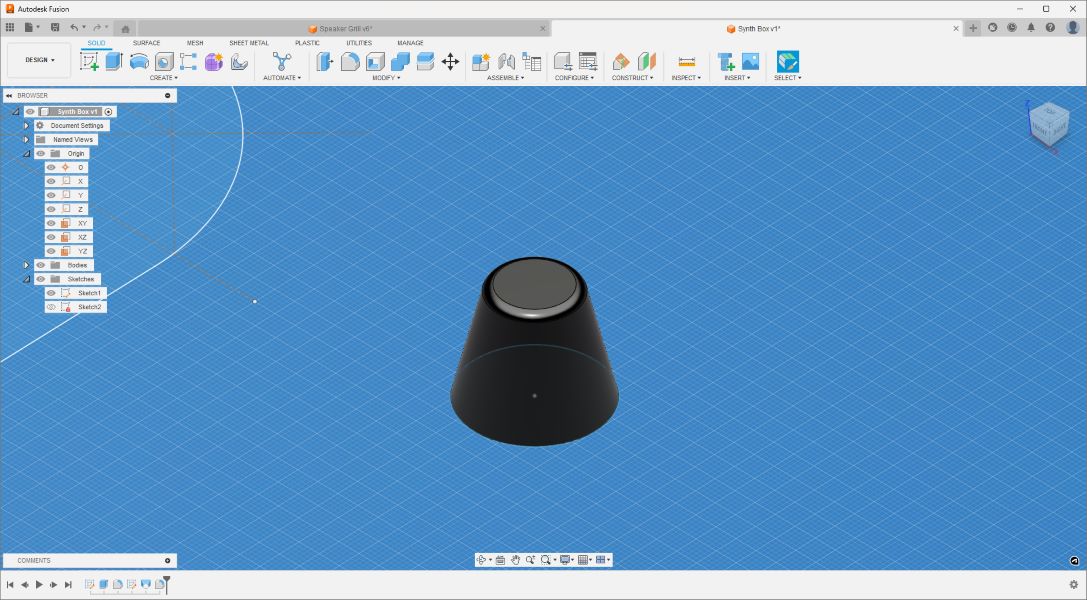
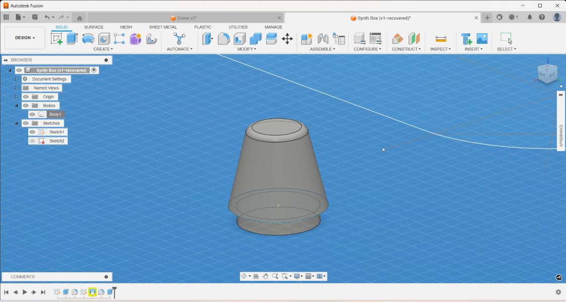
Modeling speaker housing:
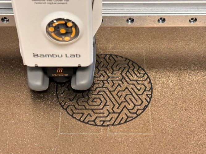
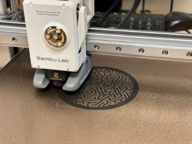
Once the file was prepped and ready to go, I was excited to try out the new Bambu A1 3D printer that Fab Lab Barcelona acquired. I simply exported my Fusion 360 file as an .STL and opened it in the Bambu slicer. You can download their proprietary software HERE.
As for settings, I did not make any adjustments and applied the general, default settings to see what would happen. The printer is quite good and did not need any setting adjustments anyway. I printed a few tests - while there were all prints I could work with, I had to adjust for speaker ring size and maze trace width. Both of these settings I just fixed in the Fusion 360 file and re-exported the .STL files to get the better, final prints.
Test 1:
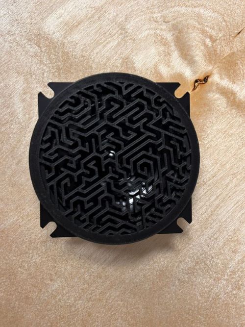
Above, the maze trace here is too thin at 1mm, and the diameter of the grill ring is too wide.
Test 2:
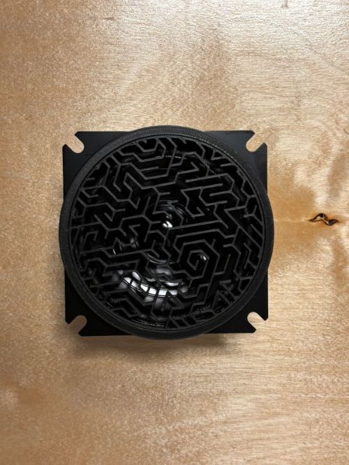
Maze trace thickened to 1.5mm, diameter of grill ring shortened.
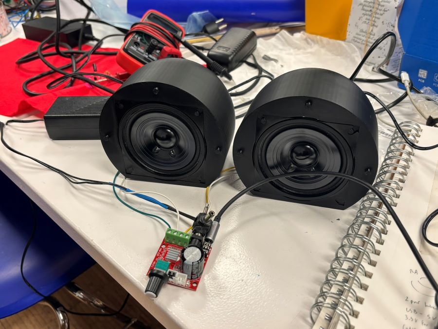
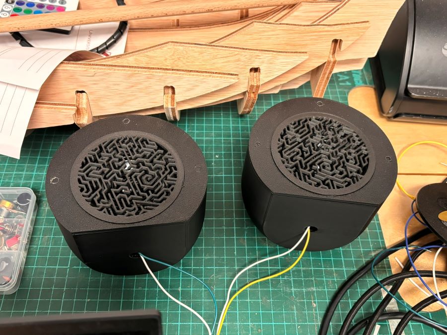
Here are the finalized speaker housing - I used the default settings on the Bambu and they turned out well. I then tested their sound with the amp I have been using for my project development and fit the grills onto the housing:
Buttons
It was important for interaction to add buttons to the synth and make them as user-friendly as possible since my MIDI board includes six tactile switches that are hard and small to the touch. I explored with 3d button design and 3d printing buttons for the first time, which was fun!
I started out printing some tests in generic PLA, starting with two versions; one flat bottomed and another hollow-bottomed to fit around the tactile switch button.

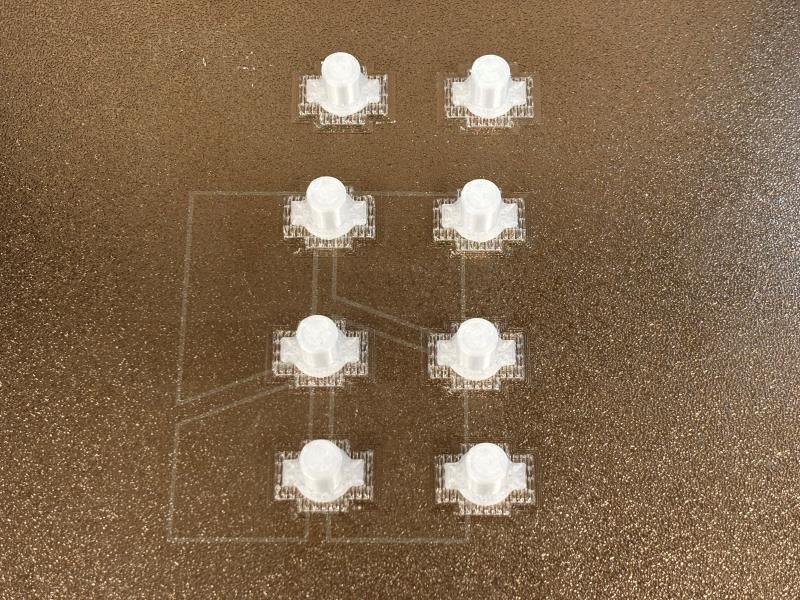
After these were printed, I realized the hollow-bottomed design, while a good idea in theory, actually do not make pressing the switch any easier - quite the contrary in fact because of the 4 pegs on each corner of the tactile switch that kind of render the button less effective.
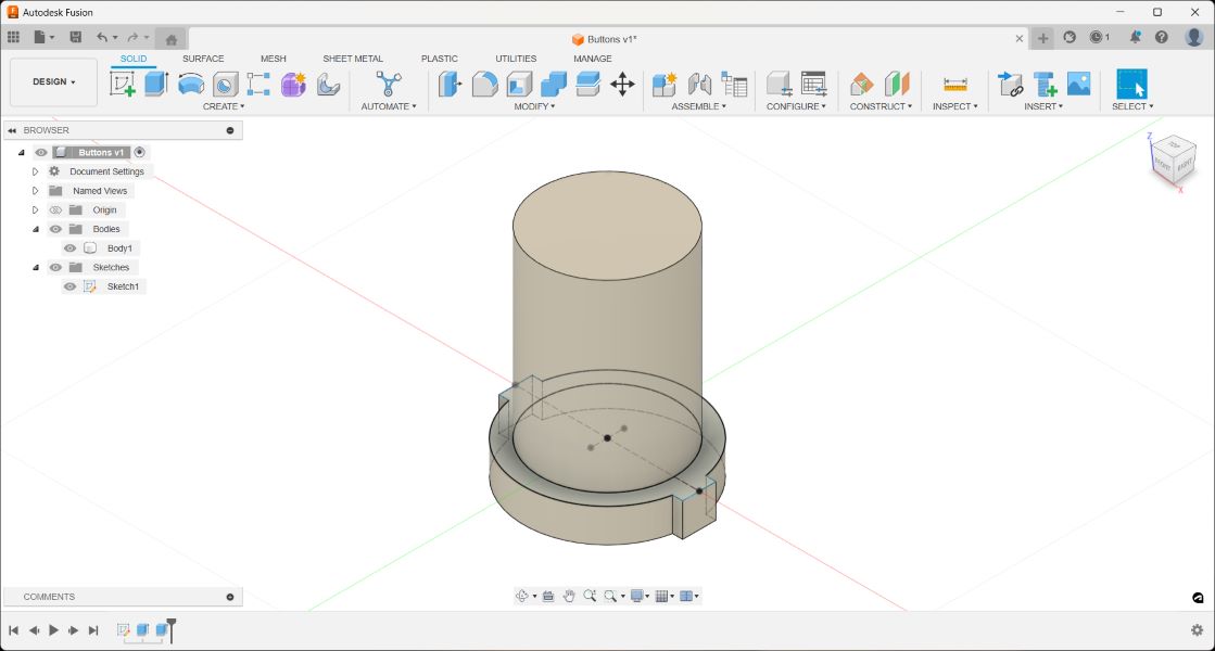
The flat bottomed version was OK, but really the better option I think will be to make a version with a protrusion in the middle to actually directly tap the tactile switch pad. Thanks to Susanna Brohlani for that suggestion as well!
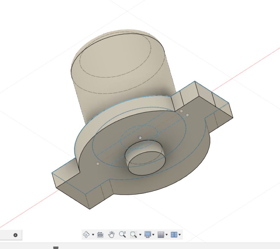
So I went forward with that design and then realized that to improve further, it would be best to print a sole button pad instead of individual buttons, which can be very fickle to keep in place lest you design a support for each of them. The button pad should be best, and aligning each button with the board's tactile switches should be straightforward designing off of an SVG of the circuit board from KiCad in Fusion sketch environment.
Synth Legs
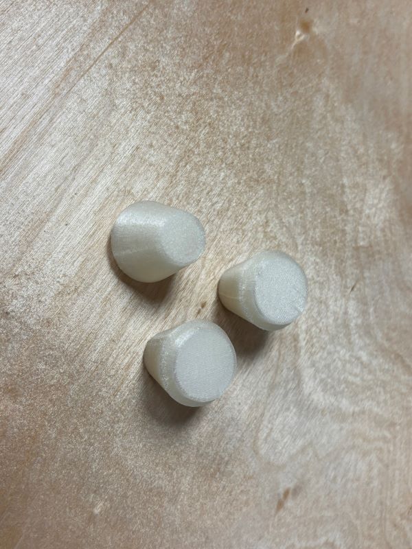
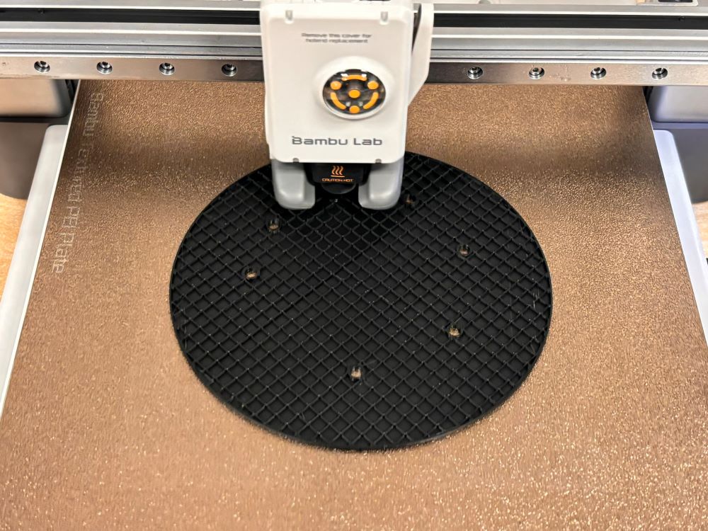
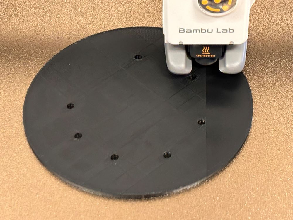
I wanted the synth to be elevated as to not lay flat on the ground. I've been interested in methods of digitally fabricating furniture parts so I wanted to make some small legs for the synth body. My initial thought was to cast and mold these supports because I wanted to make them out of silicone for better grip and avoid any console movement caused by the speaker vibrations.
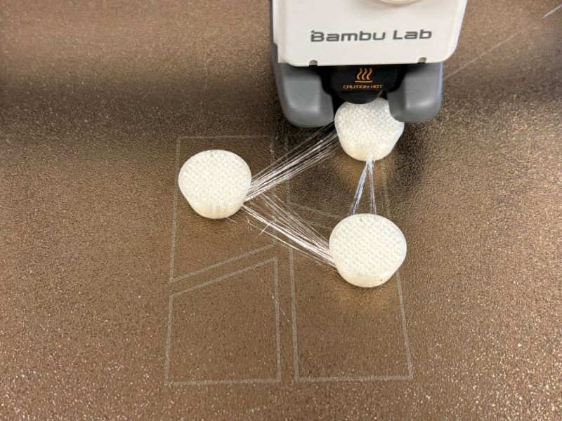
After some thought, I decided it was simpler and less wasteful to go with 3D printing. I went with the Bambu A1 since it gave me some good results printing the speaker grills. I used TPU filament (Thermoplastic polyurethane), a type of flexible and elastic 3D printing filament. It is suitable for uses requiring impact-absorption and a soft-touch surface. Examples of TPU 3D printed parts include tubes, seals, bushings and vibration dampeners.
The TPU filament available at the lab was 95A graded and we initially tried to print the file through the Bambu AMS (automatic material system), soon realizing that that density was not compatible with the AMS.
Fortunately, the A1 comes with an external spool holder, which mounts to the top of the A1. We then loaded the spool by removing the tube from filament exchanger No. 4 and connecting it to the external filament spool.
Steps
- -On the printer screen, select "Filament"
- -Select "External Spool"
- -Click "Edit"
- -Select "Generic"
- -Select "TPU"
- -Click "Load"
Once the nozzle is heated, you'll be able to load the TPU into the A1. It's good practice to cut the tip of the filament so that it's flush. The motor will start to rotate and expel filament through the extruder. Once it works, hit "done". Now that the TPU is loaded, prepare the model.
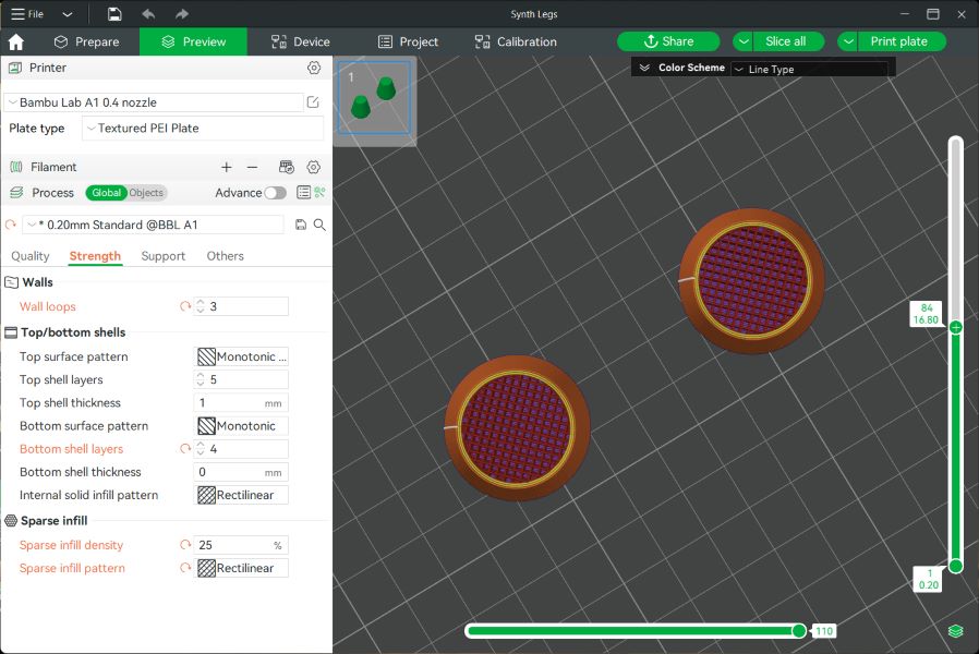
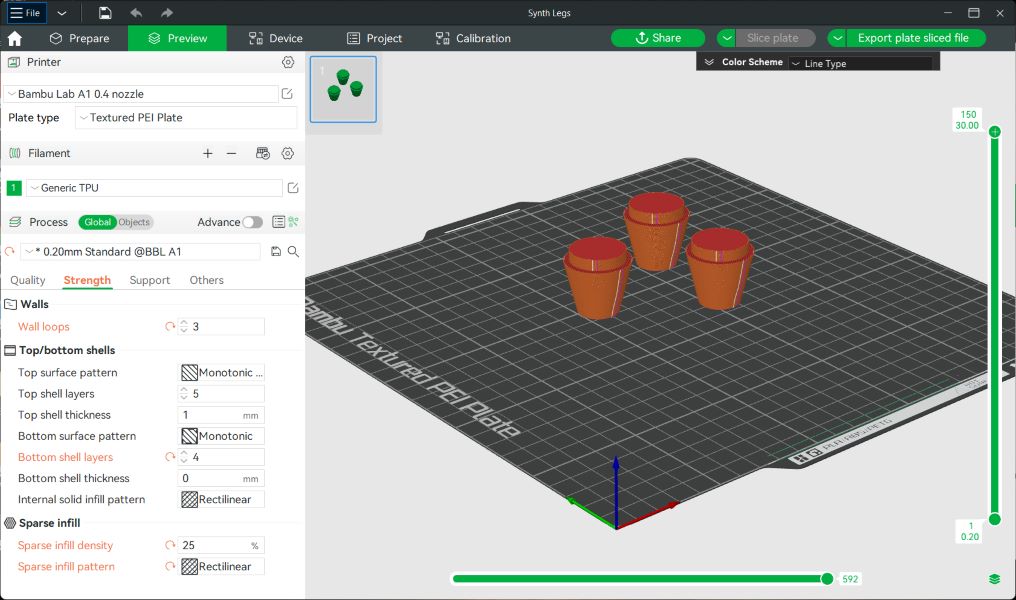
Printer Settings
- -Load your STL file into the Bambu software
- -Change the filament setting to "Generic TPU"
- -Adjust settings according to preference. I added some density to my infill (25%), had 4 bottom layers and 3 bottom layers, for example.
- -Click "Preview" to slice the file.
- -Click "Send"
- -Select your print job on the printer screen and unselect "Use AMS" to use the external spool.
SOURCES:
Touchapd
In many ways, the touchpad is the fundamental component of my final project. I want to be exploring capacitive touch for these types of devices, in order to make interactive art and furniture in the future.
My initial intention was to reference a maze in my touchpad design, however, after consulting with my instructors and advisors, I realized that making a capacitive touchpad that includes long strips of capacitive material is more complex than I anticipated, especially if I wanted to achieve an array of sounds from one single piece of material.
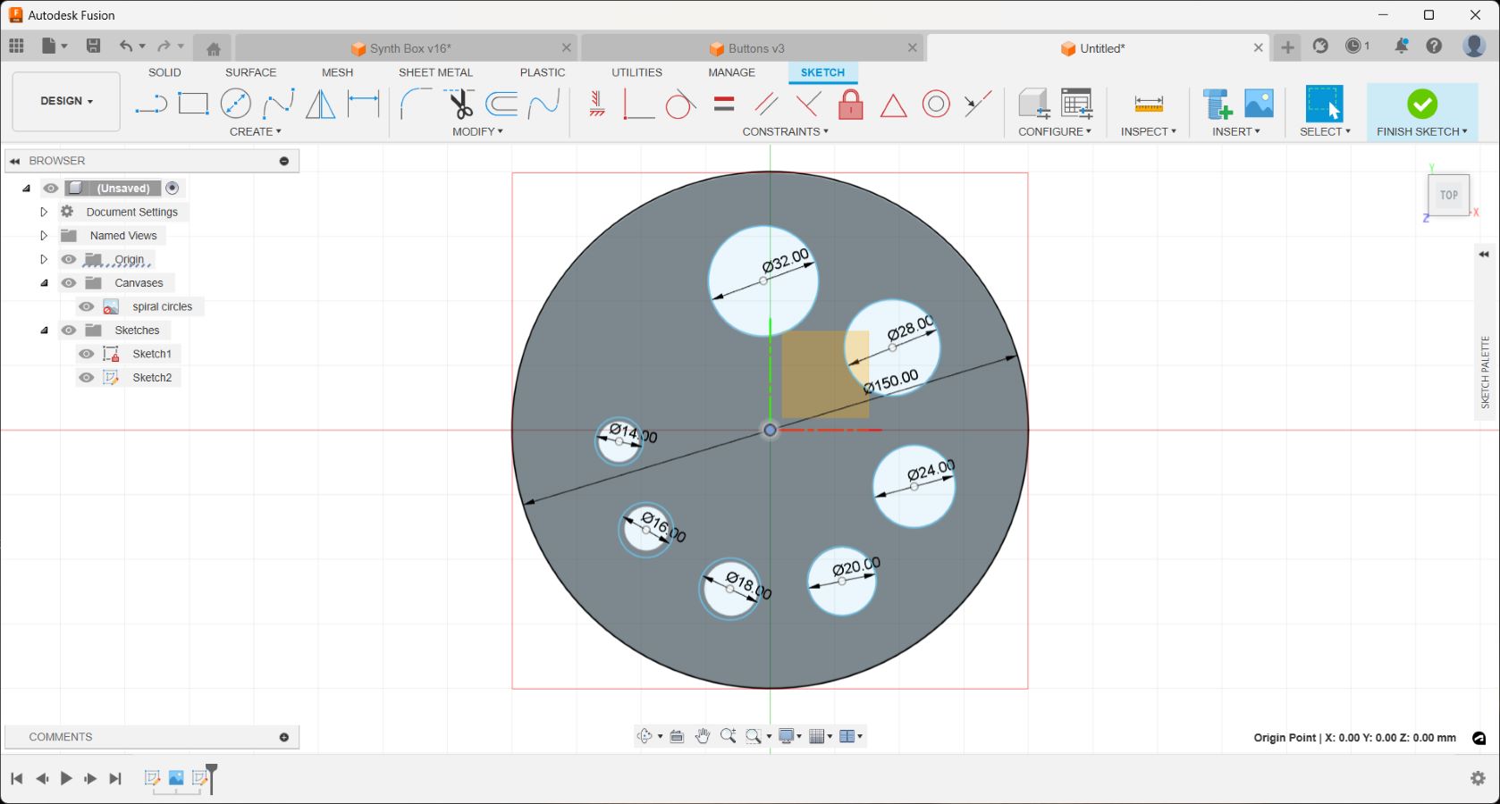
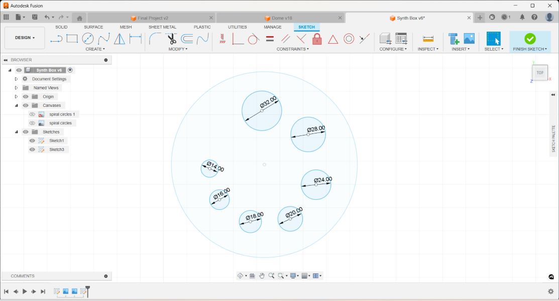
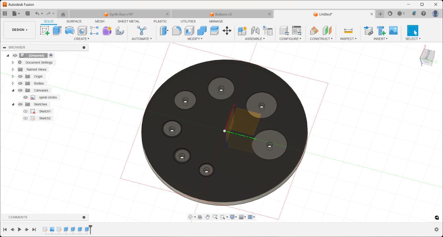
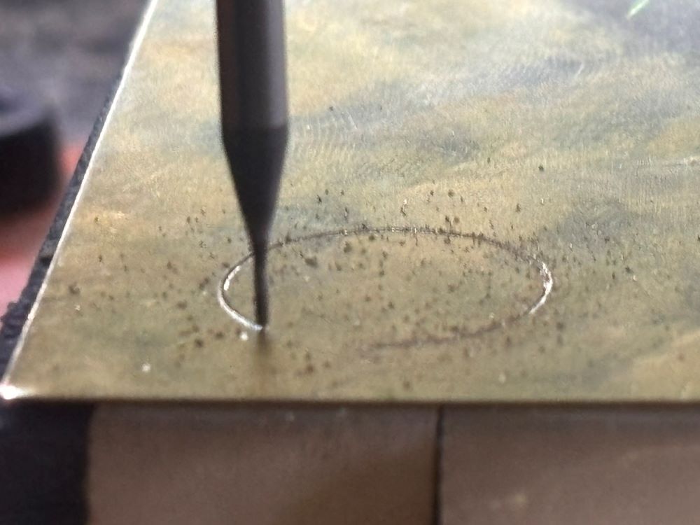
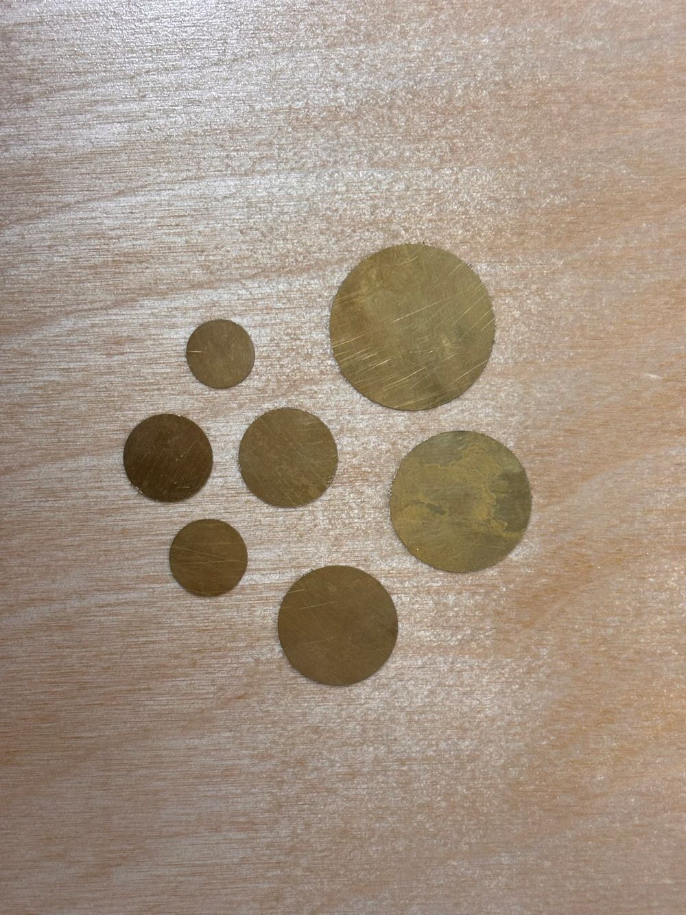
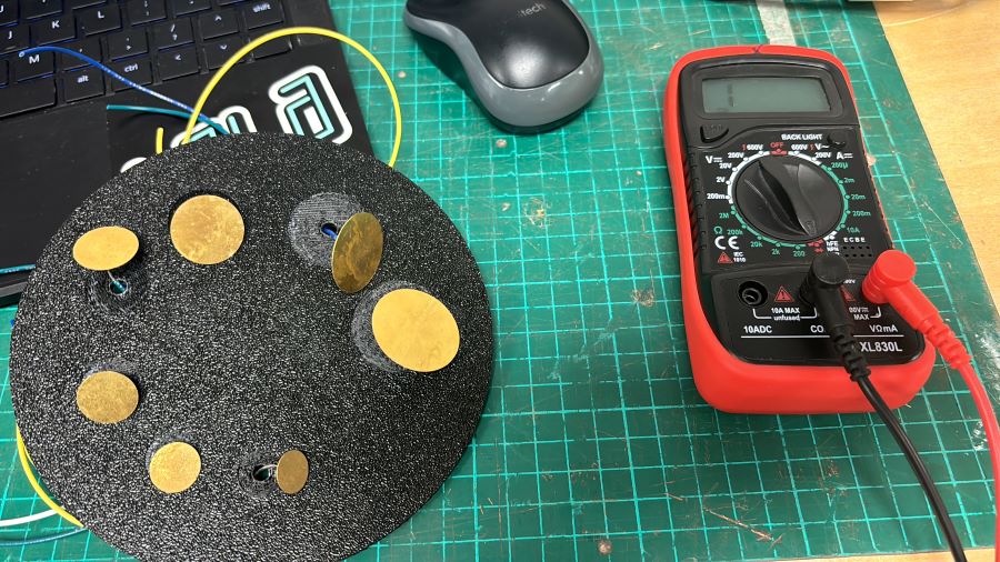
Like many ideas I have workshopped throughout this course, I will want to develop it in the future. Best to stick to more basic, achievable pursuits since so many processes are new to me. I decided to mill a thin sheet of brass in the Roland CNC machine we have at the lab to make capacitive touch buttons instead. The layout was "hand friendly" and reminiscent of a spiral movement, which was my happy compromise:

Electronics Design + Programming
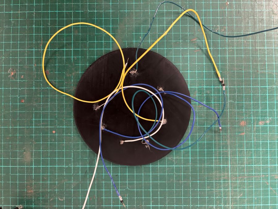
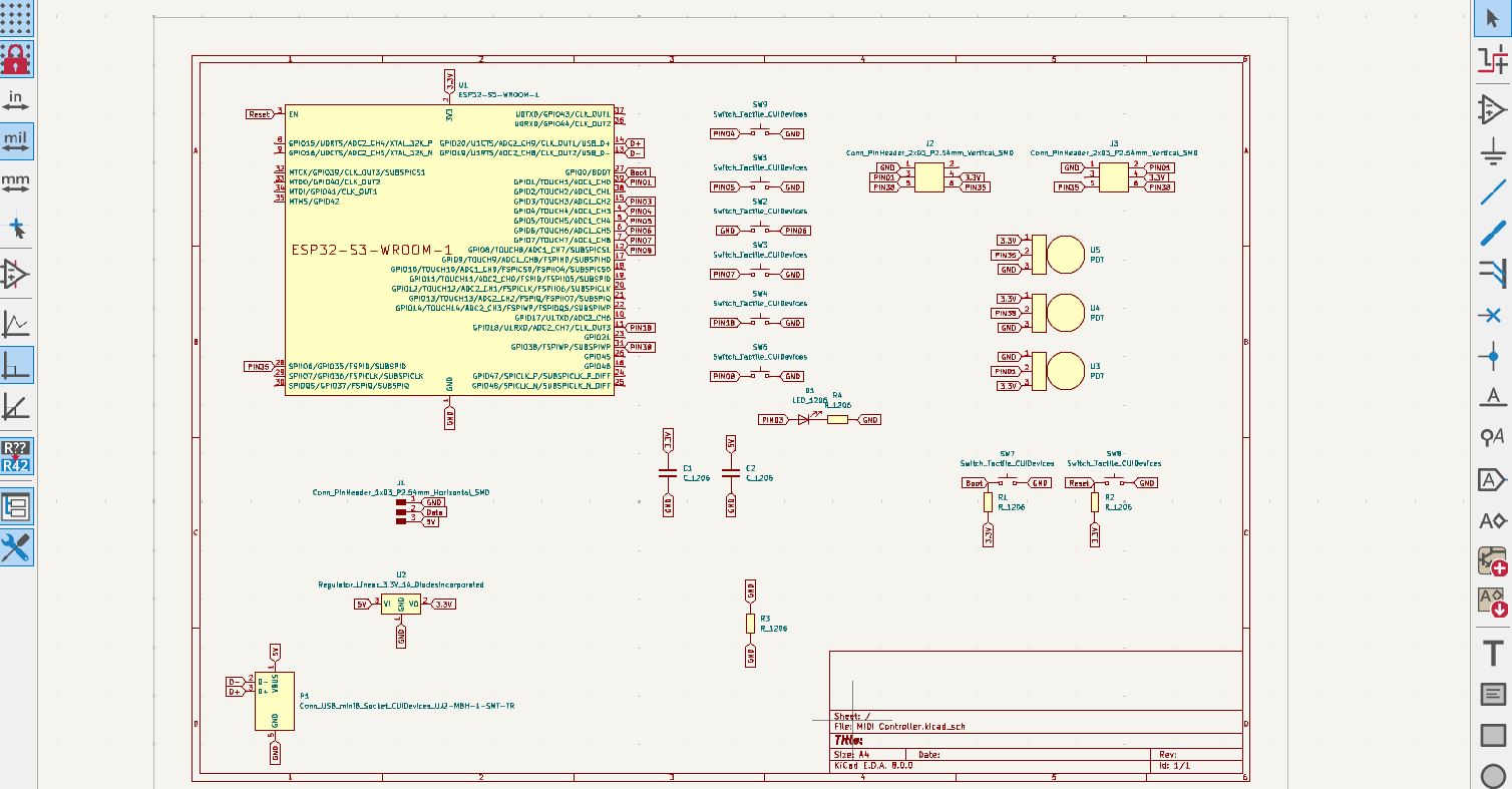
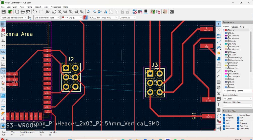
For my final project, I am using a MIDI controller device that I designed and programmed. The board is equipped with a ESP32-S3-WROOM MCU and 7 possible tactile switches that are meant to set off sound.
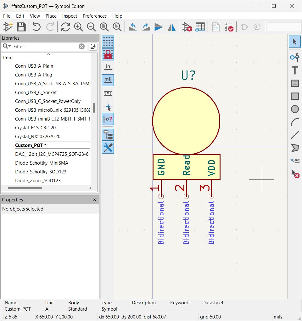
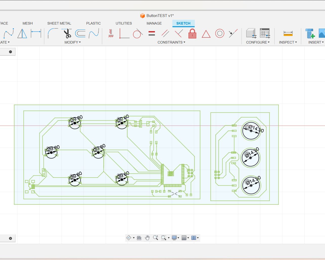
Here is the current design of the MIDI controller and a potenciometer board, for which I made custom footprints in Kicad for:

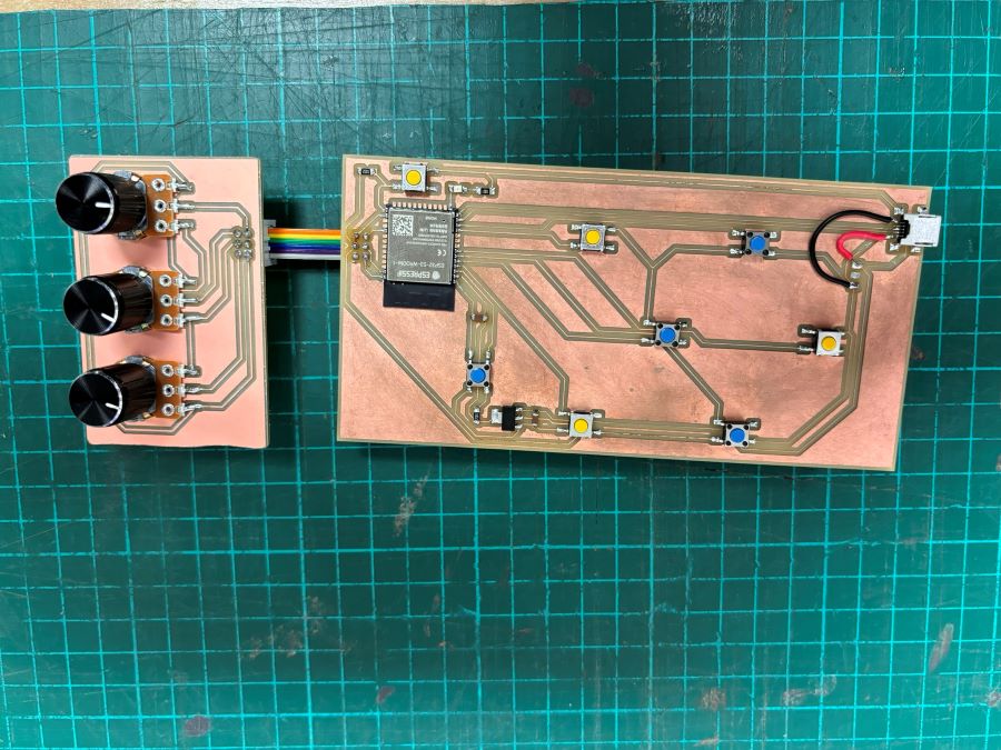
At this point, I have milled two boards and have been testing it out as a MIDI controller - my issue at this moment is the USB connection may be faulty. My board has a hard time being detected by the Arduino IDE, despite being programmable/flashed.
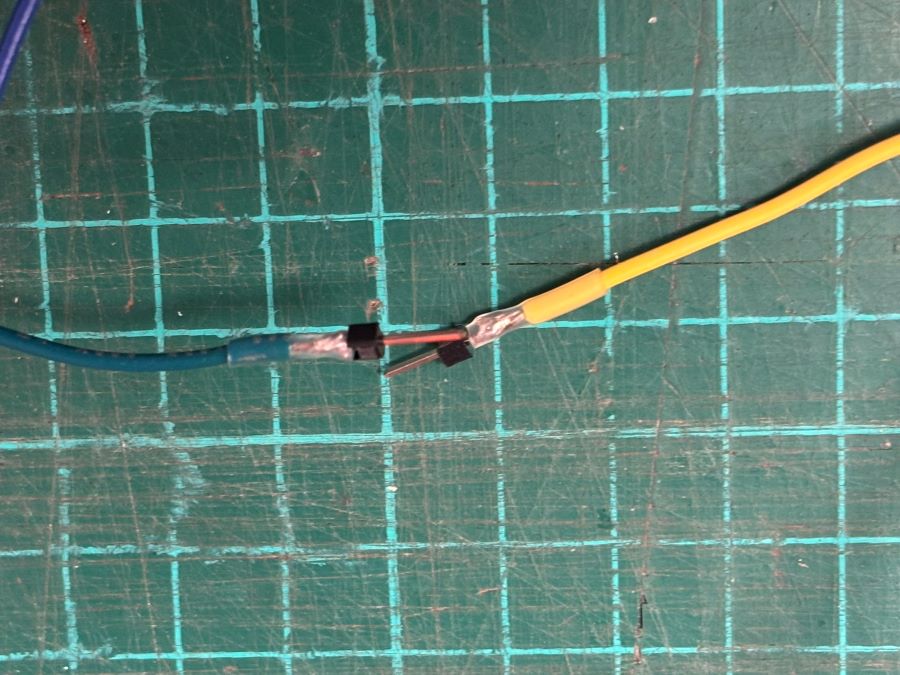
Our instructor, Josep, had to rewire some of my pins, as I had re-arranged connheader pins connecting my MIDI
and POT boards unceremoniously. While the board was able to be programmed despite the added jumper wires, best
practice is to mill again and re-work the design on Kicad.
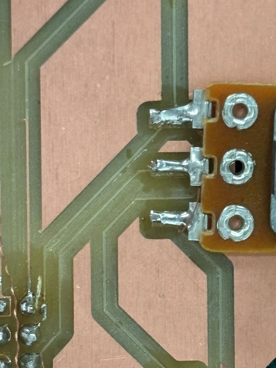
The milled traces came out too thin as well, and when I tried changing one of the potenciometer knobs, the whole
copper pads ripped off of the PCB surface and took the copper traces with it!
Lastly, it was recommended that I redesign my MIDI board with the USB port closer to the MCU. So, keeping that in mind, this is my path moving forward.
Protoypes be protoyping! Big thanks to Josep!
Electronics Programming
This is the code I have installed on the MIDI controller and potenciometer board:
MIDI programming:
#include "USB.h"
#include "USBMIDI.h"
USBMIDI MIDI;

const int pins[] = { 0, 4, 5, 6, 7, 8, 18 };
int butState[] = { 0, 0, 0, 0, 0, 0, 0 };
int prevState[] = { 0, 0, 0, 0, 0, 0, 0 };

int notes[] = { 40, 48, 56, 64, 72, 80, 68 };


void setup() {
  MIDI.begin();
  USB.begin();
  for (int i = 0; i < 7; i++) {
    pinMode(pins[i], INPUT_PULLUP);
  }
  for (int i = 0; i < 7; i++) {
    butState[i] = digitalRead(pins[i]);
  }
  for (int i = 0; i < 7; i++) {
    prevState[i] = digitalRead(pins[i]);
  }
}

void loop() {
  for (int i = 0; i < 7; i++) {
    butState[i] = digitalRead(pins[i]);
    if (butState[i] != prevState[i]) {
      prevState[i] = butState[i];
      if (butState[i] == 1) {
        MIDI.noteOff(notes[i], 0);
      } else {
        MIDI.noteOn(notes[i], 126);
      }
    }
  }
  delay(100);
}
POT programming:
#include "USB.h"
#include "USBMIDI.h"
USBMIDI MIDI;

const int buttonPins[] = { 0, 4, 5, 6, 7, 8, 18 };
int butState[] = { 0, 0, 0, 0, 0, 0, 0 };
int prevState[] = { 0, 0, 0, 0, 0, 0, 0 };
int notes[] = { 50, 52, 54, 56, 58, 60, 62 };

// Define pins for the potentiometers
const int potPins[] = { A9, A2, A1 };
int potValues[] = { 0, 0, 0 };
int prevPotValues[] = { 0, 0, 0 };
const int midiCC[] = { 1, 2, 3 }; // MIDI Control Change numbers for the potentiometers

void setup() {
  MIDI.begin();
  USB.begin();
  for (int i = 0; i < 7; i++) {
    pinMode(buttonPins[i], INPUT_PULLUP);
  }
  for (int i = 0; i < 7; i++) {
    butState[i] = digitalRead(buttonPins[i]);
  }
  for (int i = 0; i < 7; i++) {
    prevState[i] = digitalRead(buttonPins[i]);
  }
}

void loop() {
  // Read button states and send note on/off messages
  for (int i = 0; i < 7; i++) {
    butState[i] = digitalRead(buttonPins[i]);
    if (butState[i] != prevState[i]) {
      prevState[i] = butState[i];
      if (butState[i] == 1) {
        MIDI.noteOff(notes[i], 0);
      } else {
        MIDI.noteOn(notes[i], 126);
      }
    }
  }

  // Read potentiometer values and send MIDI CC messages
  for (int i = 0; i < 3; i++) {
    potValues[i] = analogRead(potPins[i]) / 8; // Scale 10-bit ADC value (0-1023) to 7-bit MIDI value (0-127)
    if (potValues[i] != prevPotValues[i]) {
      prevPotValues[i] = potValues[i];
      MIDI.controlChange(midiCC[i], potValues[i], 1);
    }
  }

  delay(100);
}
Questions and To Do's
As a craftsperson who did not include many digital processes (until now) in my work, I have approached my fab lab project by thinking more about the construction and materials than the "brains" or tech side; my workflow is usually hardware before software. So where I'm at now, I have to address the electronics and programming needs of my project.
I am working on the interaction between the capacitive touchpad and the MIDI controller + POT board.
Additionally, I need to figure out how to program my Pure Data patches into the Bela IDE system and include programming that will successfully interact with my custom MIDI controller board. In terms of that, I still need to refine a Pure Data patch that triggers MIDI and my capacitive touchpad at the same time.
As for the design of the synth body, I am still making some decisions as to how it will all come together. While I have the bottom part and general body shape figure out, I am considering how to integrate the speaker boxes still.
So to summarize, I need to really lean into the programming aspect of my synth, and finalize the body design. I am at a place where I have to make some final decisions, and have learned a lot about simplifying design most of all during this sprint!
I think the biggest lesson of all has been JUST DOING IT, despite setbacks and many questions floating around when making anything. I am understanding, in a really important and different way than before, that making is fundamentally about breaking the barrier between concept and manufacture. There is immense value in having a prototype, working or not.
We go through this process so that we refine our own approaches and methodologies. So that, hopefully and progressively, we can generate less waste and work in a tactful way that saves us material and refines our abilities to test and prototype.