
Week 8: Electronics Design
Here is the group assignment link for this week!
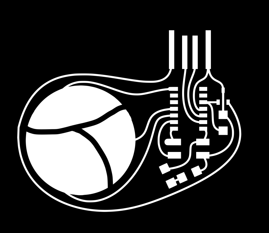
Since I want to be working with capacitive touch and am very new to electronics design and components, I based my board off of Quentin Bolsee's;s SVG PCB spline demo project.
At first, I milled a PCB board like Bolsee's, just making a slight change to the SVG file to customize the touch pads a bit. I used the exercise of copying this board as a way to understand more about PCB layouts and electronics in general. I integrated the SAMD11 microcontroller and modified the layout accordingly:
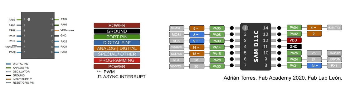
This is the SAMD11 datasheet:
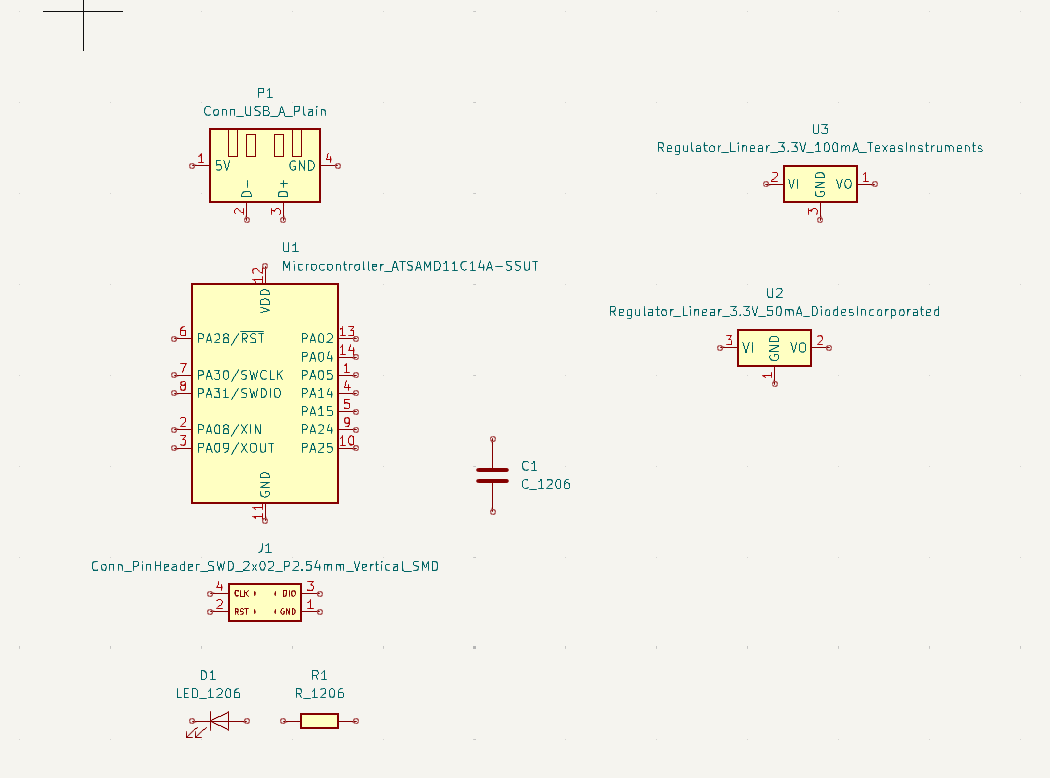
Laying out components on Kicad's shematic window to organize my pieces. I didn't trace a new board for this since I downloaded the image file directly from Bolsee's page and just adapted that via Inkscape before sending to it to MODS for milling prep:
I used the following components, as per Bolsee's SVG spline board:
- SAMD11
- USB port (plain)
- Yellow LED
- 1K Resistor
- Regulator (3.3V -5V)
- Capacitor
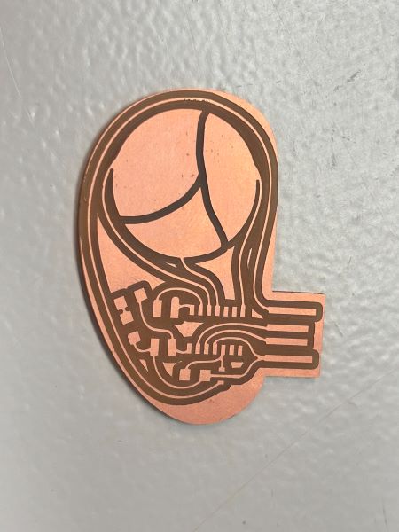
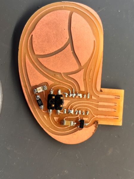
Here's the board with the soldered components. I scraped off the outer layer of copper wrapped around the USB port:
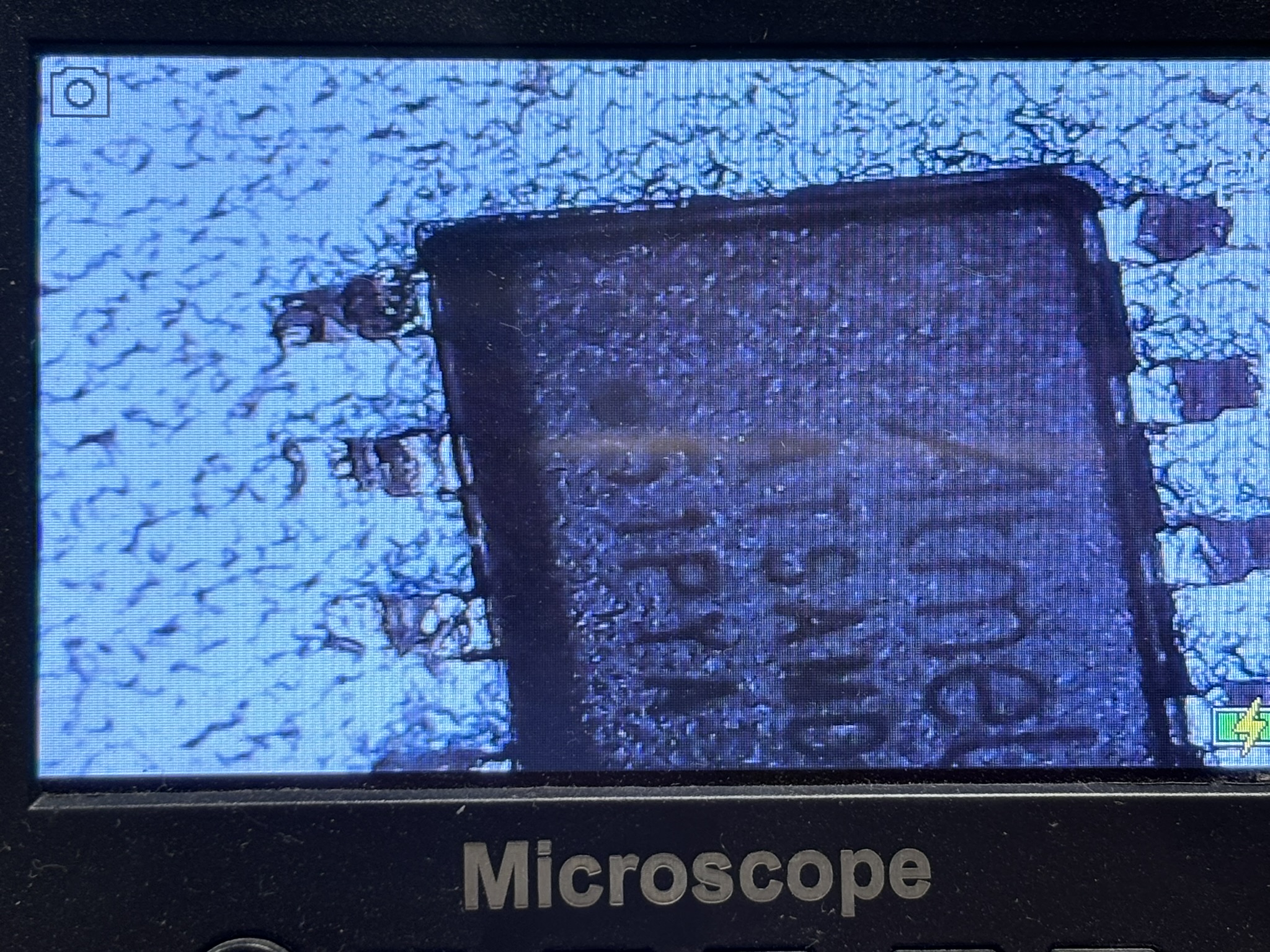
In attempting to flash the microcontroller the first time around, and testing for proper soldering/connections, it did not work. Trying to figure this out took a while, until Josep, our instructor, realized that I had soldered the microcontroller the wrong way. I was following the dot on the backside of the SAMD11 instead of looking for the etched dot on the top, where the text is.
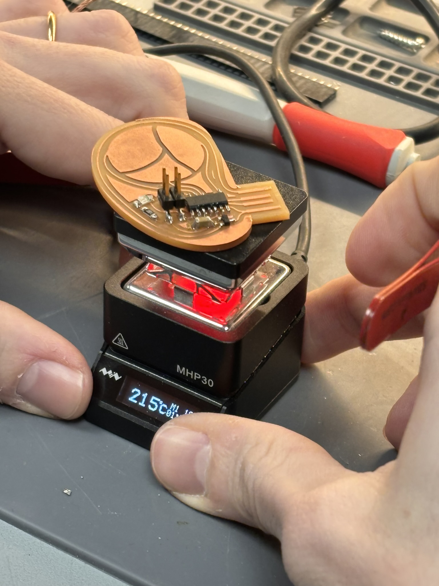
Reheating solder on heated board to loosen the SAMD11, checking for the etched dot (which indicates the proper orientation) via microscope (very helpful) and cleaning up excessive material:

Mods Setup
- Open modsproject.org/ right click anywhere / select programs/ SRM-20 milling / select Mill 2D PCB.
- Upload image file (svg or png format).
- Select your bit size. If milling traces, use 1/64 bit, if drilling holes or routing the outline, select the 1/32 bit.
- For 1/64 bit: Speed: 3 mm/s, Origin xyz: 0 for all, Jog Height: 5mm, Home (z): 20mm
- On the "mill raster 2D" box, change the offset number to 4 as a default and safety tracing. This number could vary from 3 or 4.
- Press "Calculate" to generate a preview and automatic download of the machine's tracing path. See preview with the blue lines.
Outline
- Upload your outline image file.
- Select 1/32 bit option.
- For the 1/32: Speed: 0.5 mm/s, Max cut depth: 1.75mm
Since we always begin our PCB milling with our traces, the previous other settings should work for the hole/outline milling portion of your job.
How to use as a programmer
Install firmware
After soldering all the components, I used the Quentorres board as a SAM bootloader. Another option is using the SWD programmer.
To flash the board and make it ready for use as a programmer, the easiest is to install the uf2 file available here.
IMPORTANT: If you use a MAC I recommend that you use a USB C (XIAO) to USB 2.0 (MAC) cable or a converter. The protocols of the new MACs are very restrictive to flash the XIAO. (Thank you Nuria for the report).
Step 1: press "boot" and "reset" simultaneously.
Connect your board to a computer via a USB cable. Press the button labeled "B", then hold it pressed while pressing the button labeled "R". You can then release both buttons, and the rp2040 will enter its reset mode. It that mode, it exposes its flash memory as a hard drive.
Step 2: place uf2 file on the hard drive
Download the uf2 firmware file from here and place it on the empty hard drive that showed up after step 1. After the file transfer, the board will automatically reset.
Step 3: the board is ready to use
To verify that the board is functional, you can check that it correctly shows up as a connected USB device. This device should advertise two USB endpoints: a serial port, and a swd programmer.
Flashing a SWD target
To program a SWD target, simply use the 2x5 pins JTAG connector, keeping in mind the correct orientation of the connector. On the programmer, the ground pins are located on the side closer to the edge of the board:
Make sure the target is powered and the programmer is correctly connected to your host computer. You can then flash your target using edbg, for instance:
edbg -ebpv -t samd11 -f sam_ba_SAMD11C14A.bin
If successful, the output should be:
Debugger: Alex Taradov Generic CMSIS-DAP Adapter D13C3C81 2.0.0 (SJ)
          Clock frequency: 16.0 MHz
          Target: SAM D11C14A (Rev B)
          Erasing...  done.
          Programming................... done.
          Verification................... done.
Alternatively, if you're using the Arduino IDE with the Fab SAM core installed, you can use the embedded edbg. To flash the bootloader on the target, click on Burn Bootloader:
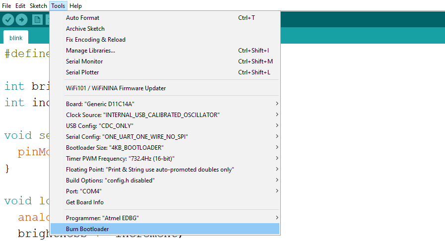
Your flashed target should then show up as a serial port.
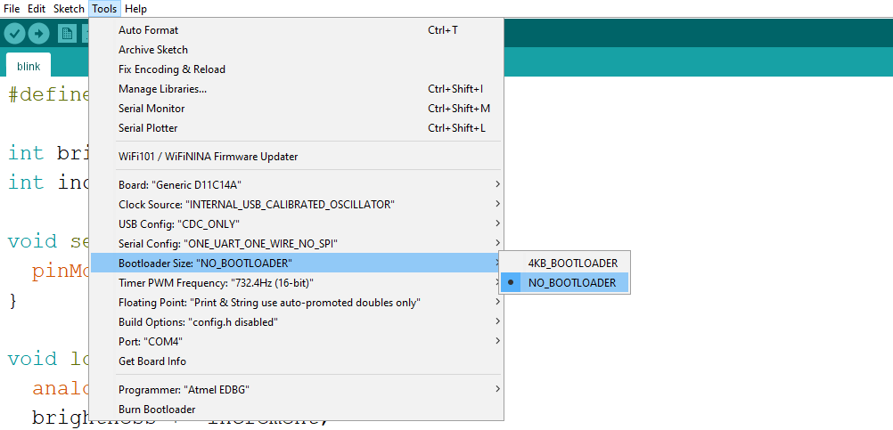
Alternatively, you can skip using a bootloader altogether to save some flash. Simply select NO_BOOTLOADER and upload; the IDE will automatically use the programmer instead of relying on a bootloader.
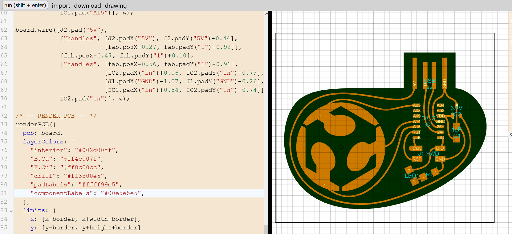
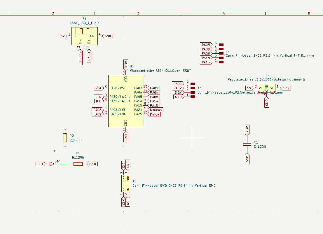
After successfully flashing this board, I moved onto actually designing one with Kicad based off of my original reference, with the addition of pinouts for using it as an output device:
Schematics:
Traces image and Kicad layout:
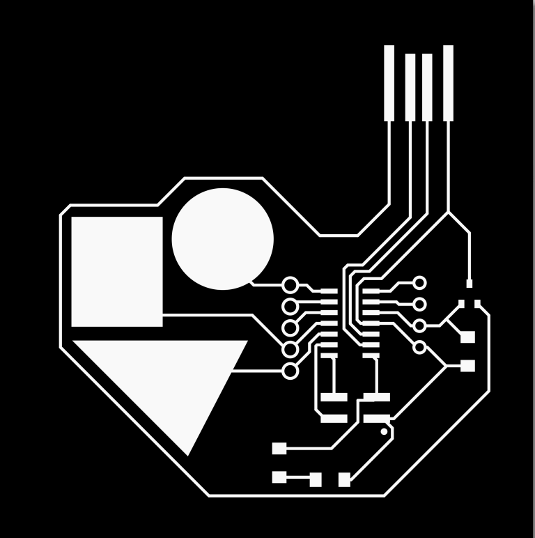
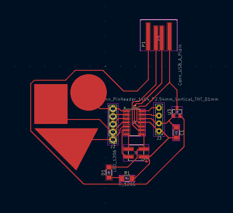
Kicad/Files
DownloadIt's important to adjust the tracing values for a correct offset between the design paths.
Go to: File / Board Setup / Net Classes
- Clearance: .4 mm
- Track Width: .3 mm
- Via Size: 1.2 mm
- Via Hole: .8 mm
Traces
- Connect all the components according to the "blue guidelines" and labels made from schematic design.
- Use "X" command to start tracing paths with it's correct offset tolerance.
- Before exporting the board check that everything is correct through the "Design Rules checker"
- Some of the Errors & Warnings are because I haven't drawn the outline of the board and not attached traces for the touch pads.
- Export board to SVG file.
Customize board
- Open SVG file using Adobe Illustrator to invert colors for mods.
- Black: removes // White: keeps
- Export "Traces" and "Outline" seperatly as PNG file with 1000 dpi quality each.
- Send to MODS and adjust settings accordingly...
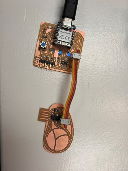
Here's my updated board - this was much easier to flash because I had practice going through the process with the original reference PCB. Also, the length of the USB port on the first board proved too short to make a stable connection, as well as the fact that I milled it using a double sided board. The conductive material on the bottom most probably did not help to establish a good connection to the computer port.

I still had to peel the copper wrapping the USB port - for the future, I will keep this in mind to prevent this through the Inkscape or Illustrator file.
Using the Adafruit library 1.1.2. version, this is the code for capacitive touch programmed on the board:
Code
          #include "Adafruit_FreeTouch.h"

                  const int ledpin = 31;

                  Adafruit_FreeTouch qt1(2, OVERSAMPLE_4, RESISTOR_50K, FREQ_MODE_NONE);
                  Adafruit_FreeTouch qt2(4, OVERSAMPLE_4, RESISTOR_50K, FREQ_MODE_NONE);
                  Adafruit_FreeTouch qt3(14, OVERSAMPLE_4, RESISTOR_50K, FREQ_MODE_NONE);

                  void setup() {
                    qt1.begin();
                    qt2.begin();
                    Serial.begin(115200);
                    pinMode(31, OUTPUT);
                  }


                  void loop() {

                    int qt1_value = qt1.measure();  // read 10-bit value
                    Serial.println(qt1_value);
                    delay(100);

                    if (qt1_value > 500) {
                      digitalWrite(31, HIGH);
                    } else {
                      digitalWrite(31, LOW);
                    }

                    int qt2_value = qt2.measure();  // read 10-bit value
                    Serial.println(qt2_value);
                    delay(100);

                    if (qt2_value > 500) {
                      digitalWrite(31, HIGH);
                      delay(100);
                      digitalWrite(31, LOW);
                      delay(100);
                    }

                    int qt3_value = qt3.measure();  // read 10-bit value
                    Serial.println(qt3_value);
                    delay(100);

                    if (qt3_value > 500) {
                      digitalWrite(31, HIGH);
                      delay(100);
                      digitalWrite(31, LOW);
                      delay(100);
                    }
                  }