Week 08 - Electronics Design
SAMD11 microcontroller: Capacitive touch board
Basics
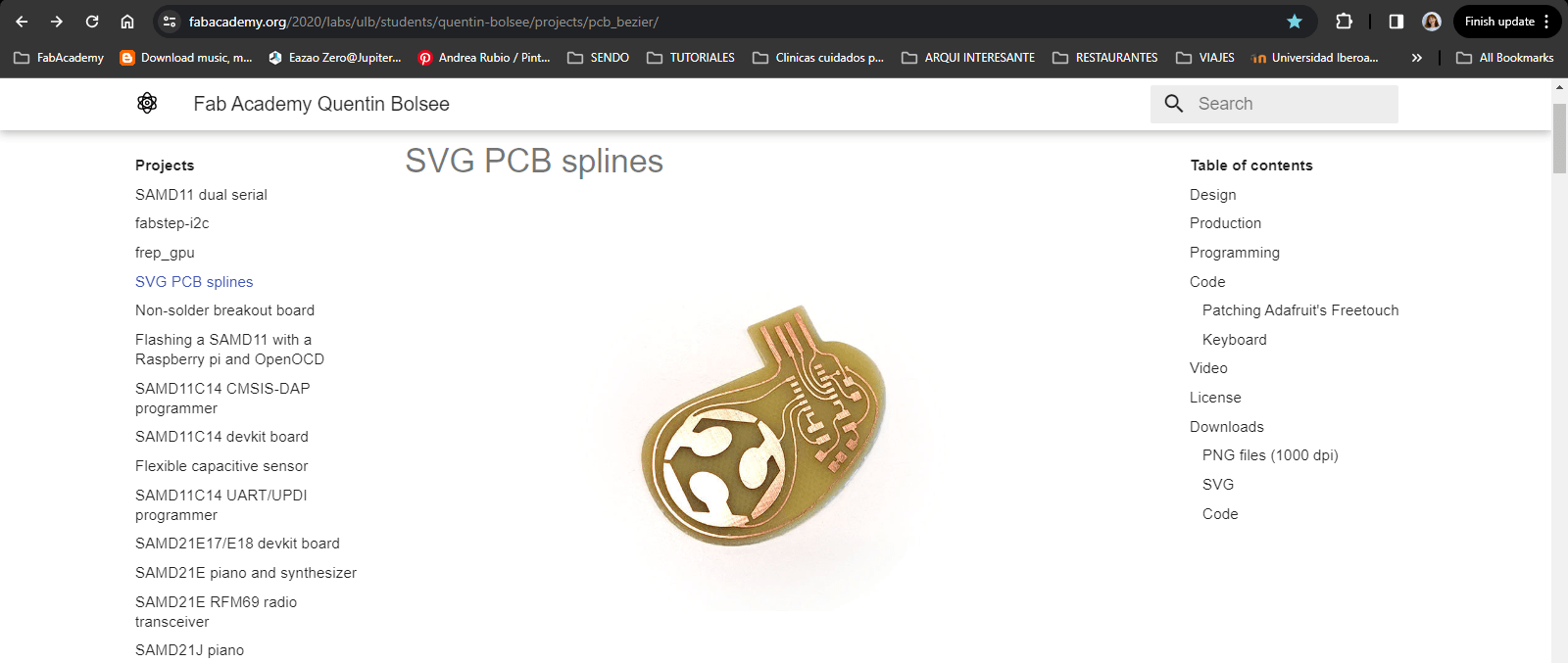
1. Usign as reference the Quentin Bolsee pcb project.
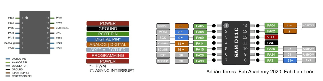
2. Understanding the SAMD11 pins and usage by checking the datasheet:
KiCad pcb design
Schematic
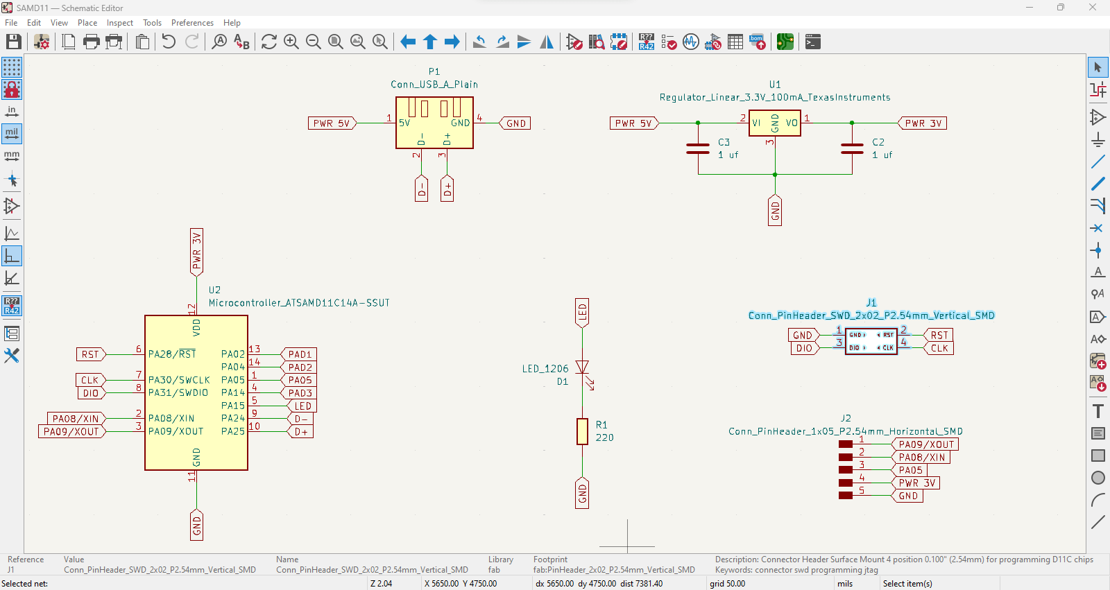
1. Following the "Quentin pcb" reference, these are the components needed:
- - SAMD11 microcontroller
- - Voltage regulator from USB (5V to 3.3V)
- - Capacitors
- - Resistor for LED (optional)
- - LED (optional)
- - Horizontal Header (amount of pins by personal choice)
- - Vertical Header (for programming board)
- - Pads (amount is by personal choice)
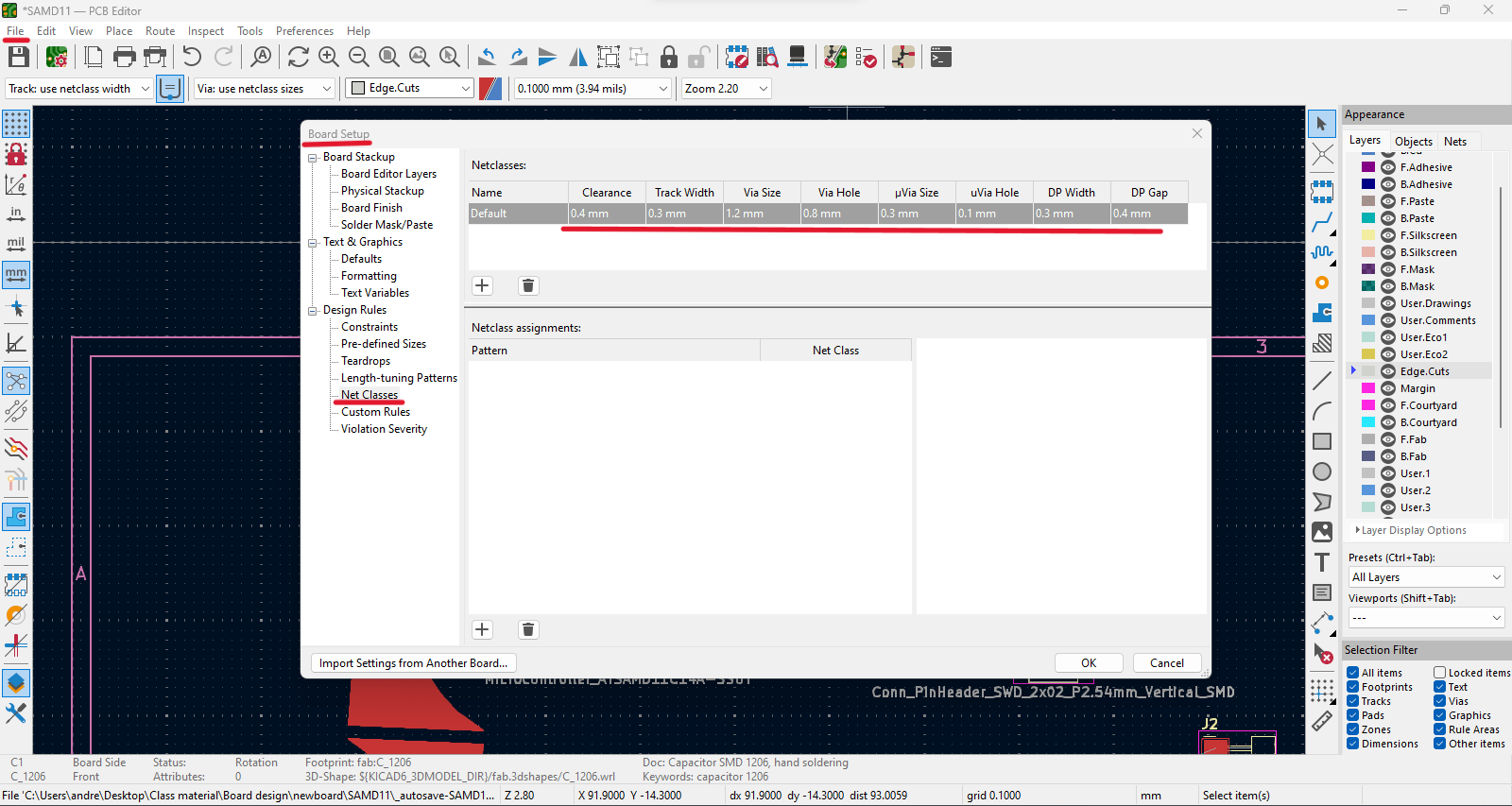
***Before tracing: Set as default
It's important to change the tracing values for a correct offset between the design paths.
Go to: File / Board Setup / Net Classes
- - Clearance: .4 mm
- - Track Width: .3 mm
- - Via Size: 1.2 mm
- - Via Hole: .8 mm
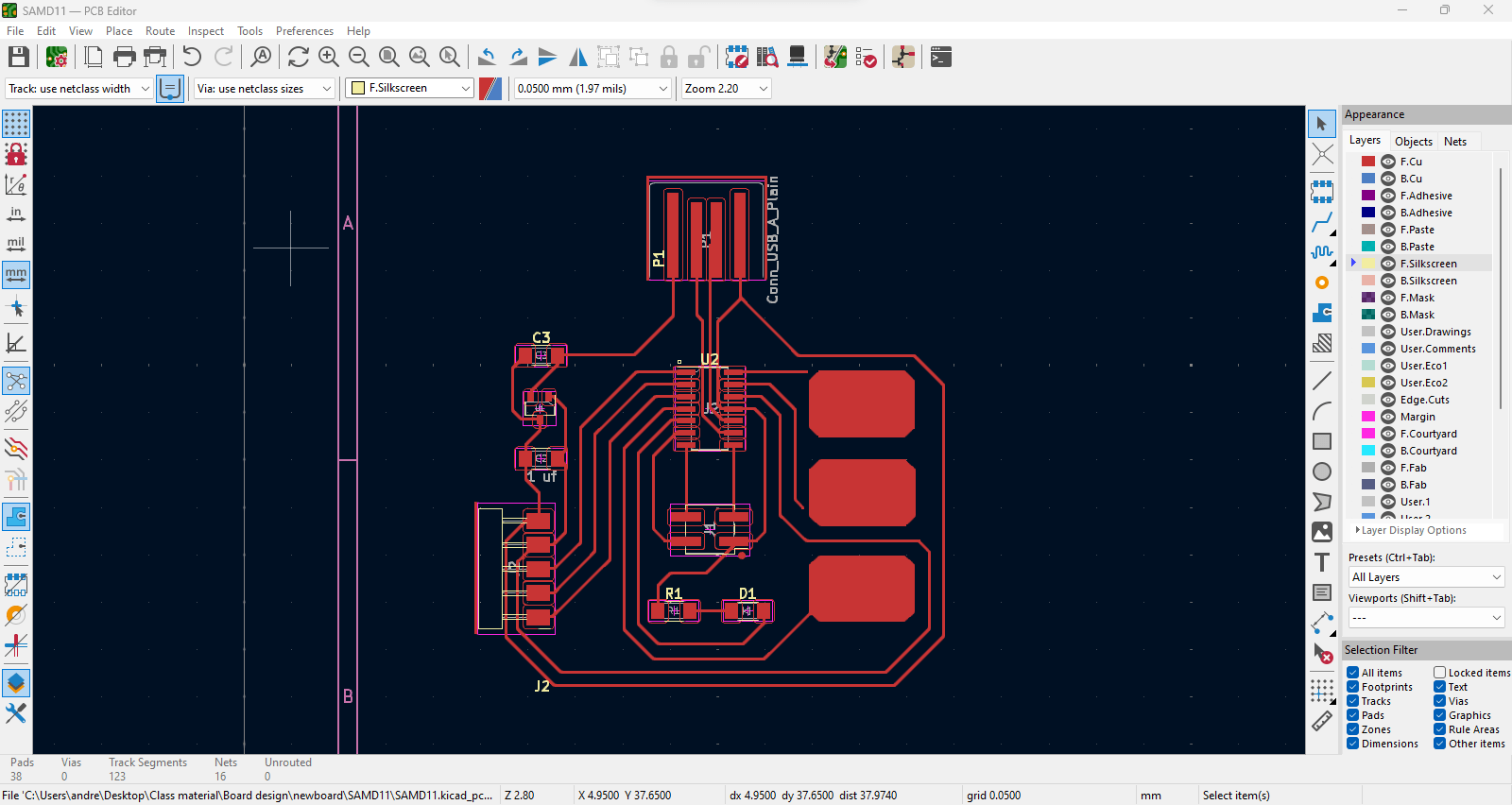
Traces
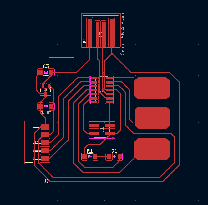
1. Connect all the components according to the "blue guidelines" and labels made from schematic design.
2. Use "X" command to start tracing paths with it's correct offset tolerance.
3. Before exporting the board check that everything is correct through the "Design Rules checker":
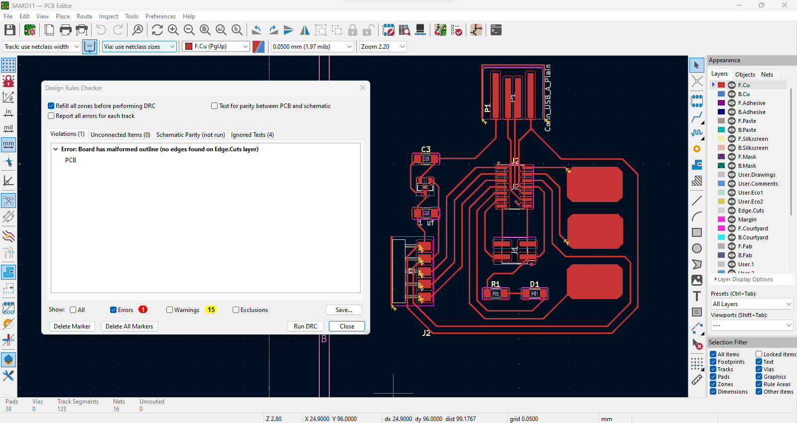
4. Some of the Errors & Warnings are because I haven't drawn the outline of the board and not attached traces for the touch pads.
5. Export board to SVG file.
Customize board
1. Open SVG file using Adobe Illustrator to invert colors for mods.
2. Black: removes // White: keeps
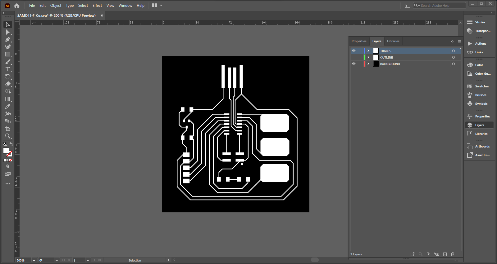
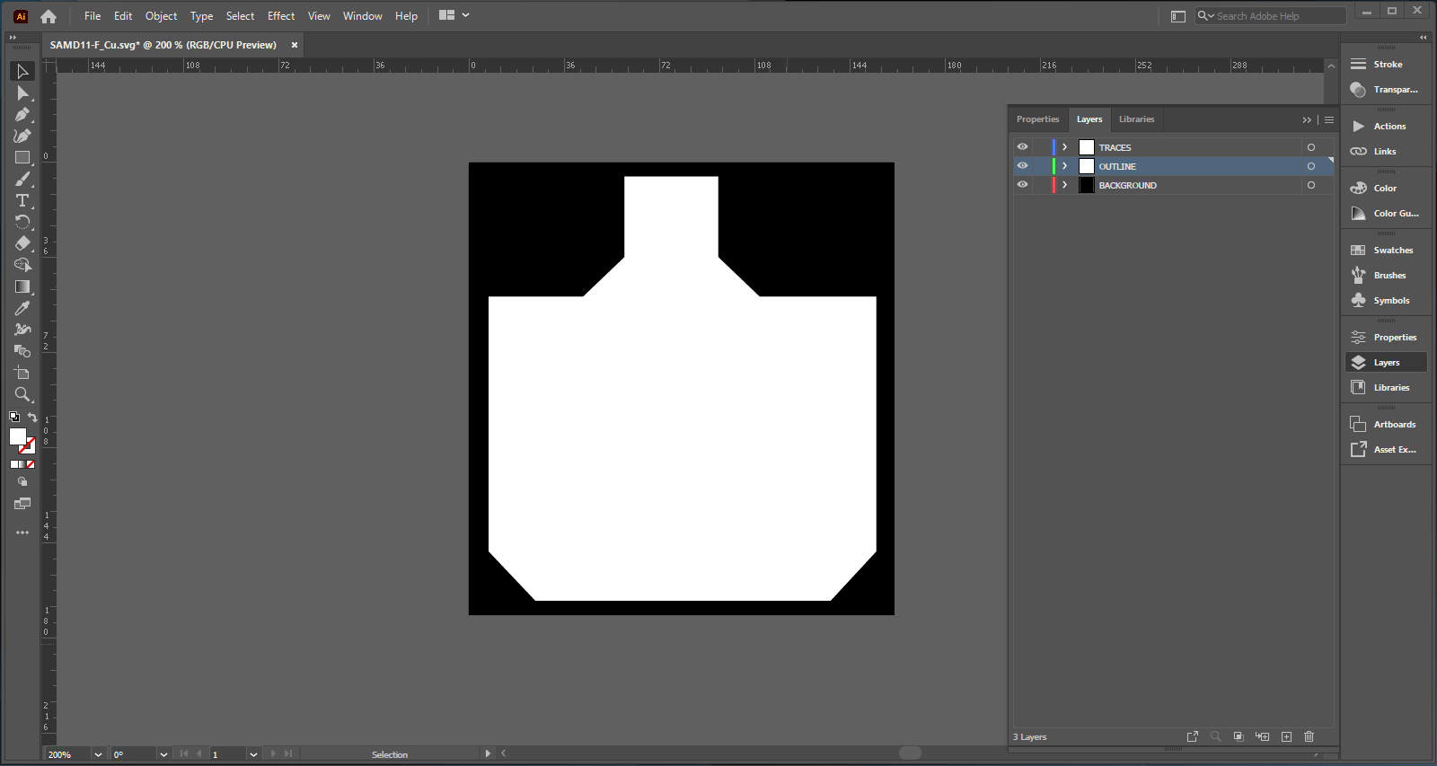
3. Export "Traces" and "Outline" seperatly as PNG file with 1000 dpi quality each.
Modsproject parameters
1. Open modsproject.org / right click anywhere / select programms / look for SRM-20 milling / select "mill 2D PCB".
2. Upload the Tracing file that was customized.
3. Select from the box below the option mil traces (1/64), we begin with the smallest bit to trace our design.
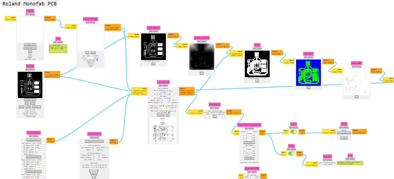
4. On the "Roland SRM-20 milling machine" box we change the following settings according to the 1/64 bit:
- - Speed: 3 mm/s
- - Origin: x,y,z = 0
- - Jog height: 5 mm (elevation of the bit each time it moves)
- - Home (z): keet high just for safety of the bit
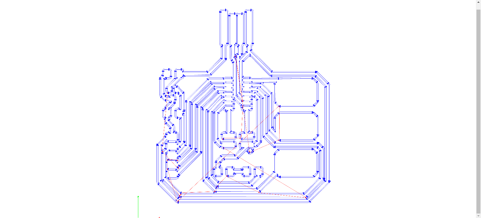
5. On the "mill raster 2D" box, change the offset number to 4 as a default and safety tracing. This number could vary from 3 or 4.
6. Press "Calculate" to generate a preview and automatic download of the machine's tracing path. See preview (blue lines).
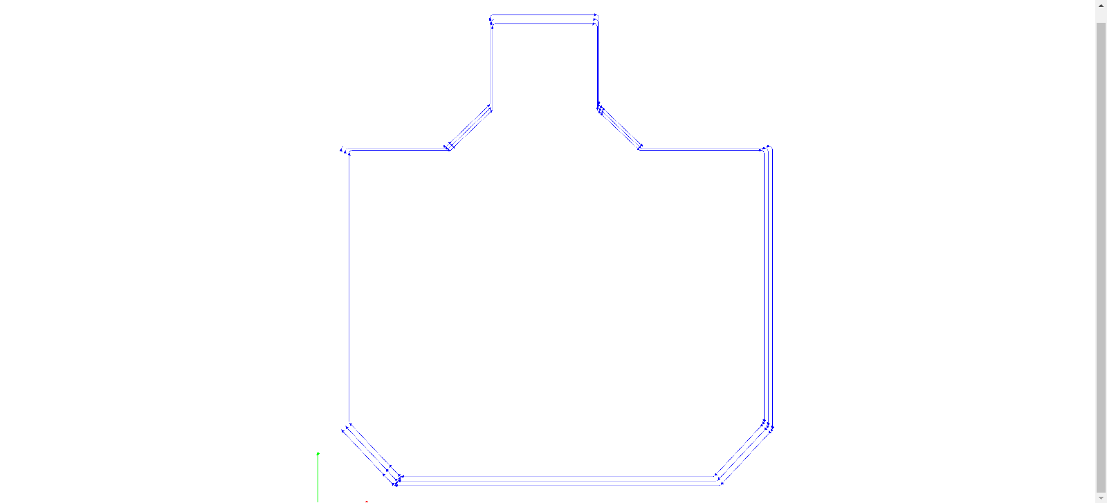
Outline
7. Upload first the Outline png file
8. Select from the box below the option mil outline (1/32), we continue with the bigger bit to do the final cut of the board.
9. On the "Roland SRM-20 milling machine" box we change the following settings according to the 1/32 bit:
- - Speed: .5 mm/s (we need to lower the speed to avoid pushing the bit and breaking it)
10. Press "Calculate" to generate the preview and new file for making the holes.
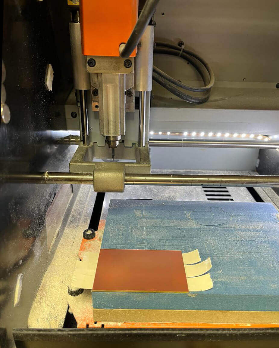
Roland SRM-20 milling machine
Setting PBC board & milling bits
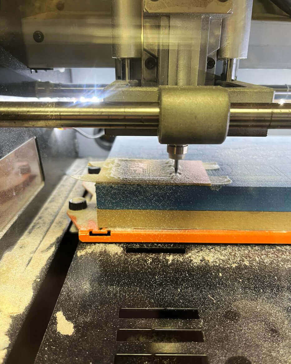
1. [First image - left] Grab PCB and apply double side tape on the non-copper face. Leave extra space for peeling the side and not affect the base leveling.
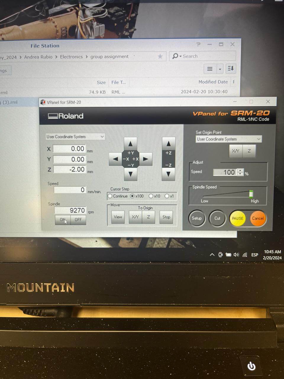
2. [Second image - left] Open software / Set XY and Z using up/down/right/left keys until it's leveled.
3. [Third image - right] Change bit to 1/64 since we are starting with the tracing file / Set Z carefully dropping the bit so it touches the board.
***IMPORTANT: Make a spindle test to ensure the bit is leveled and avoid missed cuts.
4. [Fourth image - right] On the software, select "Cut" and add the tracing file / press "Output" to start.
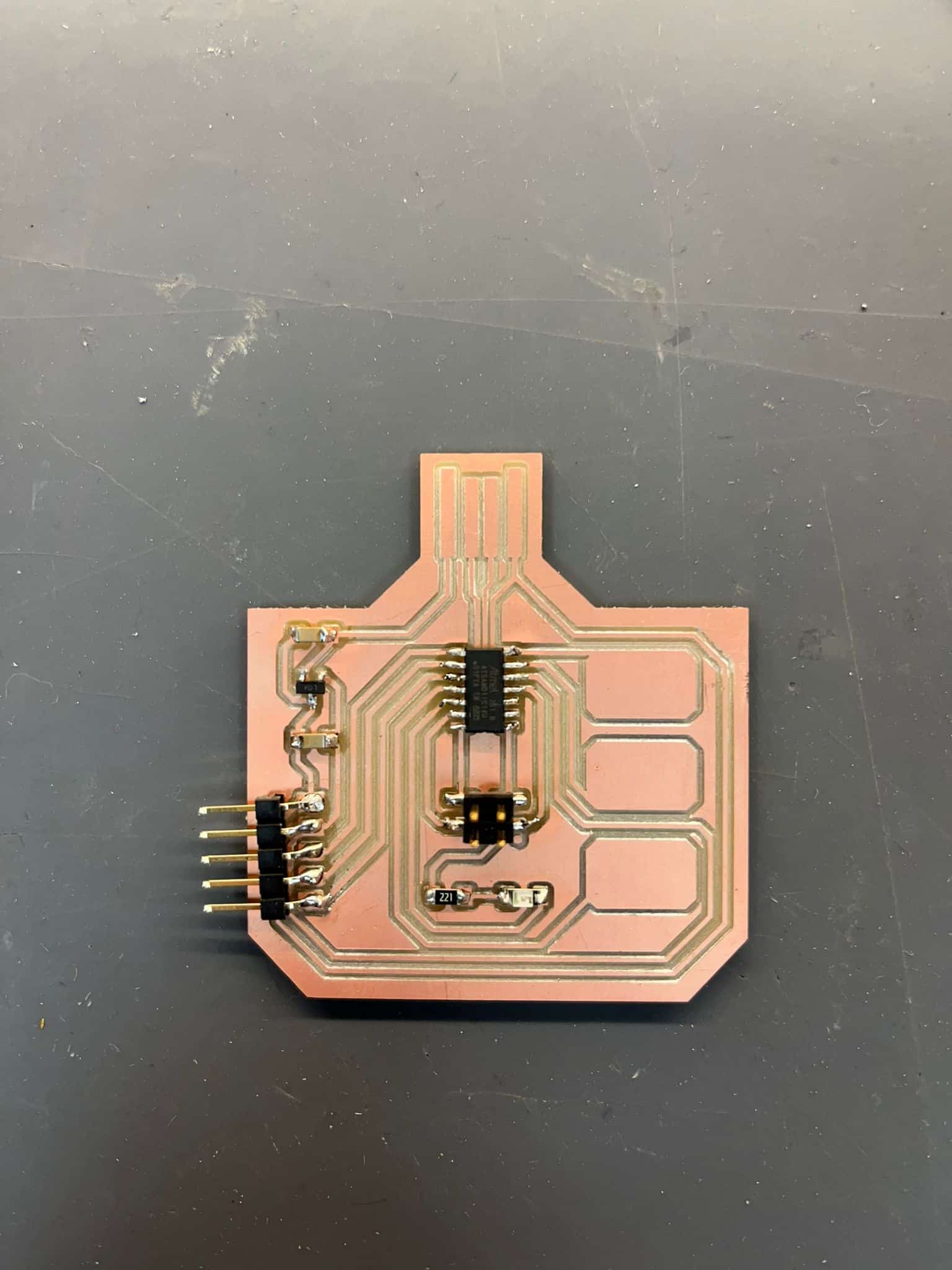
Components + Soldering
- - ATSAMD11C:(1)
- - Voltage regulator: 3.3V (1)
- - Capacitors:(2)
- - Resistor: 221 OHM (1)
- - LED: Yellow clear 1206 SMD (1)
- - Male Header: Vertical 2x2 pin (1)
- - Header: Horizontal 5 pin (1)
***LEARNINGS***
1. Check tracing on KiCad + MODS + Components
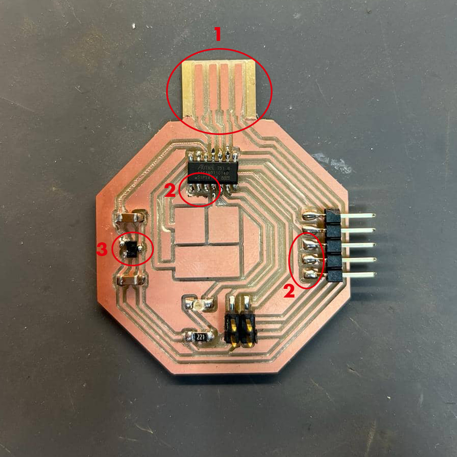
Here are some of the mistakes pointed out on the first board design milled and soldered.
- 1: Backwards projection on KiCad.
- 2: No trace connecting SAMD11 and horizontal header.
- 3: Wrong voltage regulator.
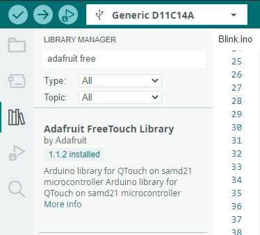
2. Wrong version of library for Arduino
By default I was downloading the 1.1.3 newest version but I really needed an older version which was the 1.1.2
Arduino set up
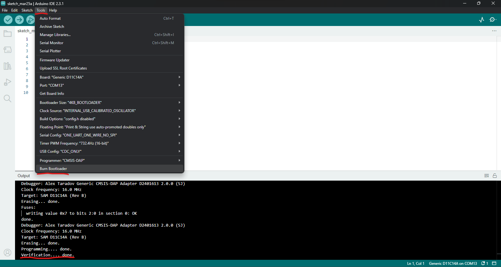
Bootloader through Quentorres board
1. Follow the instructions and documentation of the Quentorres board here.
2. Add the zip library mentioned // Connect the board // Verify information below.
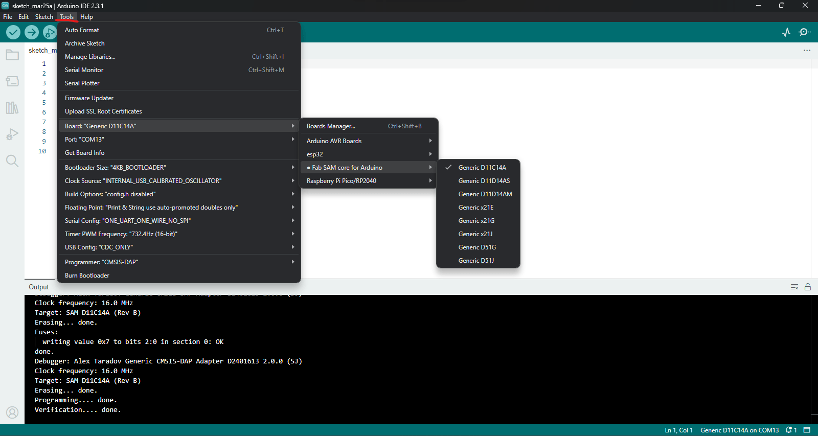
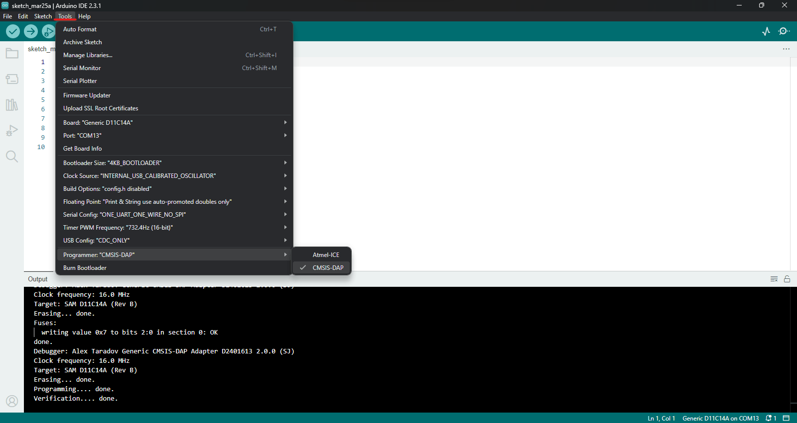
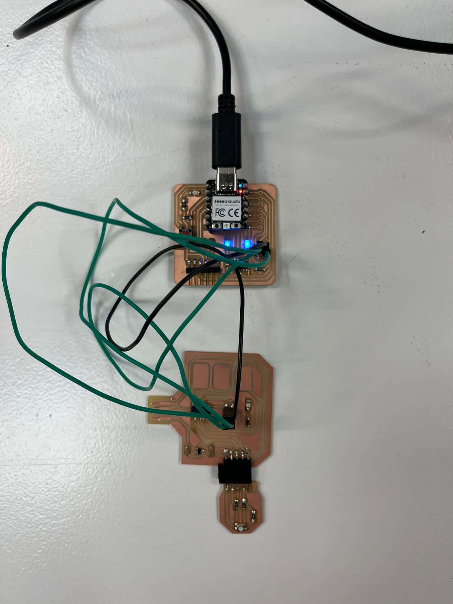
3. Once everything is correct, connect physically GND, CLK, RST, DIO from Quentorres to your pcb design and Run "Bootloader".
Test programming
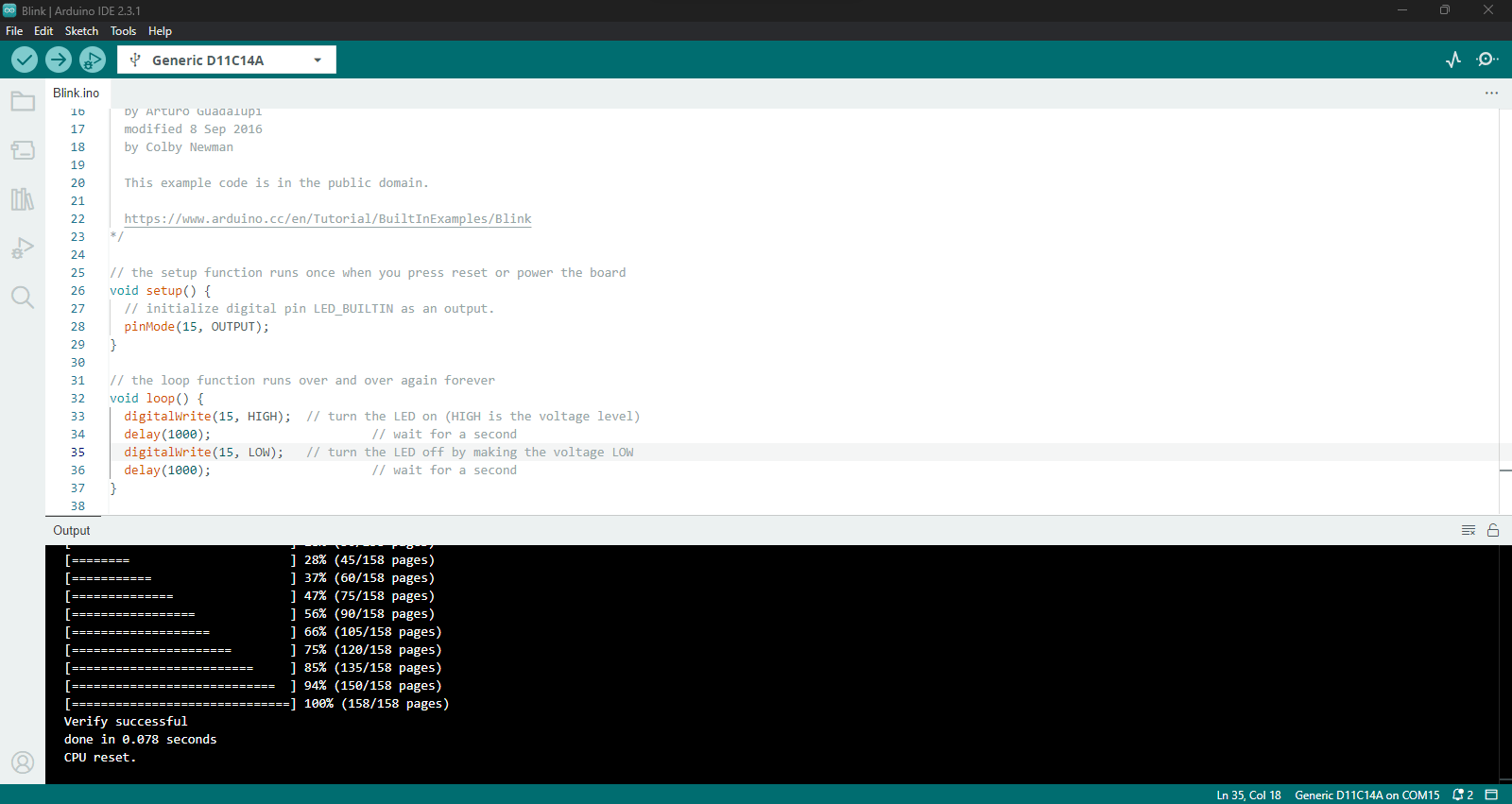
"Blink" library example
1. Clik on: File / Examples / 01.Basics / Blink
2. Indicate the location of LED pin which is 15
3. Verify and Run code.
Capacitive touch programming
Libraries & define touch pads
1. Make sure you have the correct "Adafruit" library, it should be the 1.1.2. version.
2. Define the touch pads according to the SAMD11 pins, which are: 2, 4, 14
3. Verify and Run code.
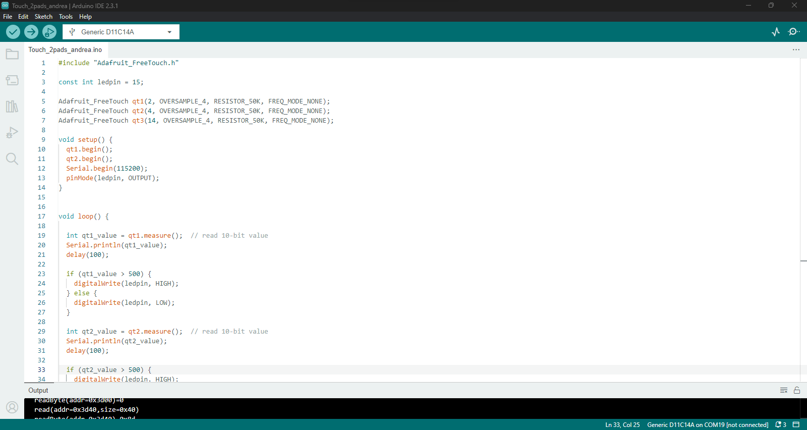
Code
#include "Adafruit_FreeTouch.h"

        const int ledpin = 15;

        Adafruit_FreeTouch qt1(2, OVERSAMPLE_4, RESISTOR_50K, FREQ_MODE_NONE);
        Adafruit_FreeTouch qt2(4, OVERSAMPLE_4, RESISTOR_50K, FREQ_MODE_NONE);
        Adafruit_FreeTouch qt3(14, OVERSAMPLE_4, RESISTOR_50K, FREQ_MODE_NONE);

        void setup() {
          qt1.begin();
          qt2.begin();
          Serial.begin(115200);
          pinMode(ledpin, OUTPUT);
        }


        void loop() {

          int qt1_value = qt1.measure();  // read 10-bit value
          Serial.println(qt1_value);
          delay(100);

          if (qt1_value > 500) {
            digitalWrite(ledpin, HIGH);
          } else {
            digitalWrite(ledpin, LOW);
          }

          int qt2_value = qt2.measure();  // read 10-bit value
          Serial.println(qt2_value);
          delay(100);

          if (qt2_value > 500) {
            digitalWrite(ledpin, HIGH);
            delay(100);
            digitalWrite(ledpin, LOW);
            delay(100);
          }

          int qt3_value = qt3.measure();  // read 10-bit value
          Serial.println(qt3_value);
          delay(100);

          if (qt3_value > 500) {
            digitalWrite(ledpin, HIGH);
            delay(100);
            digitalWrite(ledpin, LOW);
            delay(100);
          }
        }
Group assignment
On the link below you can find the complete process of this week's group assignment, covering machine usage and setting up parameters for PCB milling. Click here
Resources
Samdino from Adrian Torres
Deepu K // Fablab Kochi, Kerala
Riichiro Yamamoto // Fablab Barcelona
Josep Martí // Fab Lab Barcelona lead instructor
Adai Suri // Fab Lab Barcelona instructor
Files
Download the KiCAD ZIP package here.