Outside Body - CNC Routing
You can read more about out CNC router here and read about a previous CNC milled project from Computer Controlled Machiningweek.
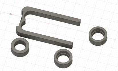
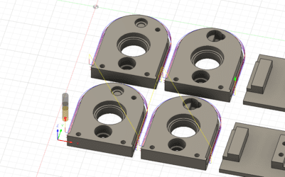
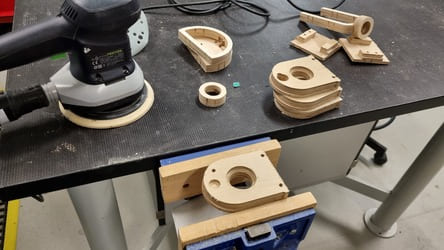
The Different Parts
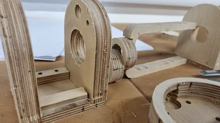
The main body of the hubs is made from 18mm plywood, so I kept that in mind while designing the outside parts. The thickness allowed me to inset the bearings and motor into the wall and avoid having a separate bearing holder. Most of the dimensions were adapted from the design from Machine Building Week but the dimensions edited slightly. To get the press-fit finish for the bearings I designed the holes to be the actual size so with some sanding I could make the perfect fit.
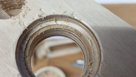
The bearing hole is tiered so that only the outside race is pressed against the inside wall which allows the bearing to turn without the potential of catching.
There is also a hole for the motor to sit on. The wires unfortunately exit out the back of the motor so there is a deeper section for the wires to go in and then back out again at the side of the motor.
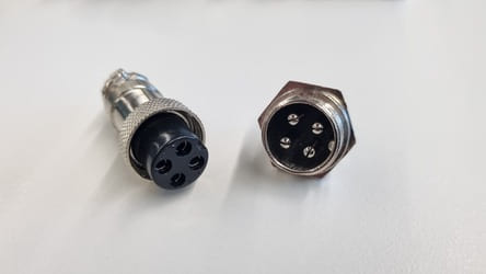
Then near the bottom there are two holes for the fastening bolts and a hole for the plug to be inserted in. On the inside of the plug there is a nut which is screwed on to keep it from falling / being pulled out.
Around the edge there is a cut in which is where the shell will overlap with the faces of the hub but the cut out allows it to lay flush.
The back wall is the same as the front just mirrored and had two extra holes which I didn't end up using.
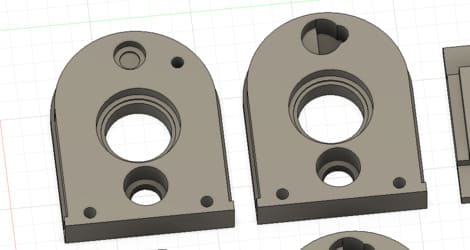
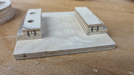
The base has a step so that the front and back walls can sit down on it and an upright face where the bolts will be screwed into. There are holes for the threaded inserts which are about 2mm oversized for the intended bolt size.
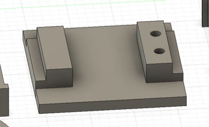
There are also holes on the top of the walls for the PCB to be fastened down.
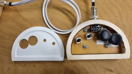
The controller was based around the size and shape of the PCB and has 4 holes in the base for threaded inserts to hold the PCB down.
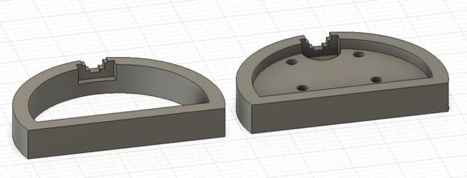
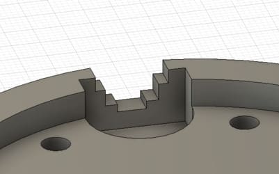
The plug hole horizontally is nearly possible because the controller is split along the center. However, I has getting issues with it not being able to mill the curved surface so I remodeled it with a stepped finish that can be smoothened out afterwards.
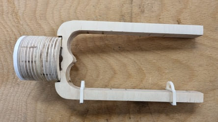
The flyer is quite a simple shape just the height of the hub limited how large you could go which was unfortunate.
The flyer has two rings which is where the 3D printed threaded insert will be pushed in.
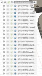
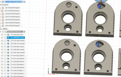
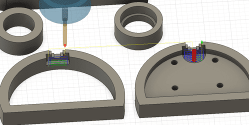
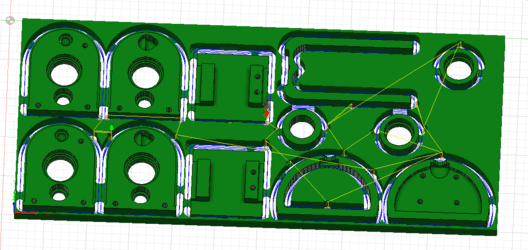
The Milling
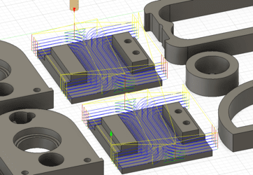
Inside of Fusion 360 I went through and set up all the milling steps. It was quite awkward as there was lots of different depths and a few different milling operations.
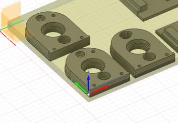
Started by setting up and choosing the models we want to include as well as setting the origin.
4mm Flat End Mill
Strating with the processes using the 4mm flat end mill.
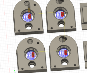
We use 2D adaptive clearing to mill out the motor hole top layer.
Then the second layer of the motor holder.
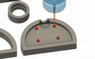
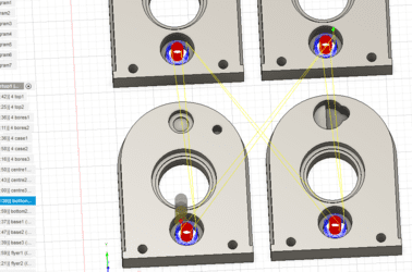
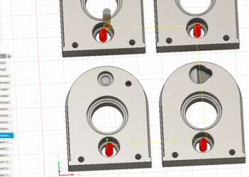
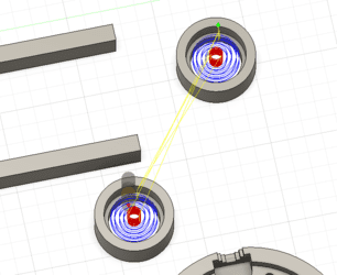
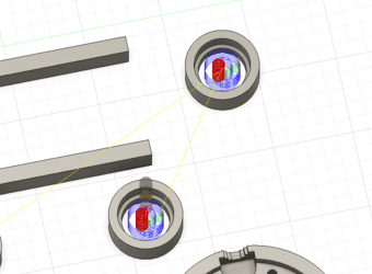
We use a boring process to mill out the bolt holes on the front and back walls.
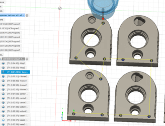
Then we bore the holes on the base.
Next is the case plug holes.
The final bores are the holes in the controller.
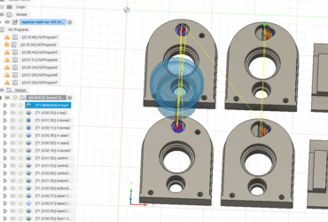
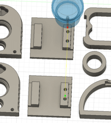
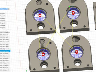
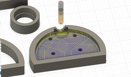
8mm Flat End Mill
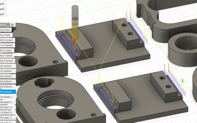
We then switch to the 8mm flat end mill for the larger cuts.
Using adaptive clearing for the bearing holes.
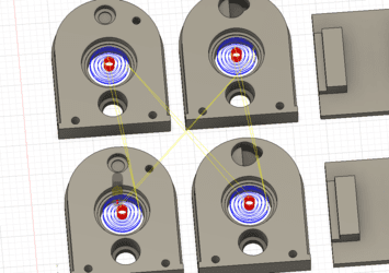
Then the hole for the plug. This ended up being missed out by accident. I finished it by hand later on.
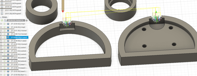
On the base we start with adaptive clearing.
Then 2D contour marking a boundary to mill within.
.png)
2D adaptive clear to clear away the remainder.
We mill out the centers of the flyer rings.
Then clearing out the inside of the base of the controller.
Then the lip on the edge of the front and back wall faces.
And finally the cutout.
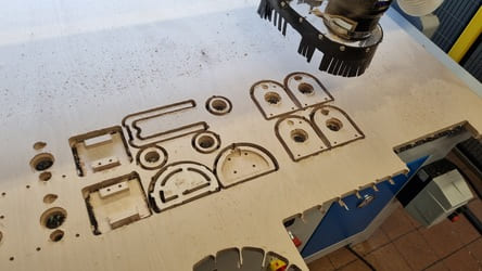
Issues
As I have mentioned the plug holes were missed the front and back faces so that had to be fixed afterwards. The lip was also missed but I noticed before we moved the wood from the bed so we could run it after the jobs finished.
The other issues were on the cut out we forgot to tell it to do multiple depths so the 8mm bit was doing the 18mm full depth of the wood. Fortunately, it didn't cause much of an issue, just some extra ragging. We did end up emergency stopping the machine when we noticed so had to mill it out twice.
As a safety precaution we changed out the waste extraction's dust bag just in case some embers had been generated.
Finished result.
Normally we use a stanley knife to cut through the tabs, however this time I used the dremel and a cutting disk and I found it much more successful as I made much less splitting of the wood.
Sanding and Adding Connectors
The first step in cleaning up is to cut off the tabs using a chisel.
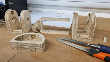
Then I use the hand rotary sander to smooth all the flat faces and edges.
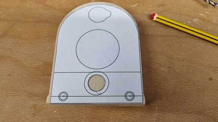
We forgot to add the processes that milled out the plug holes to the post. We unfortunately did not notice until afterwards.
So I printed out the sketch from fusion 360 to use as a template and marked where the holes needed to go.
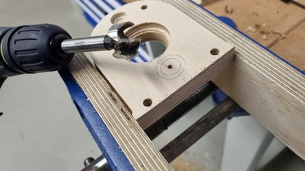
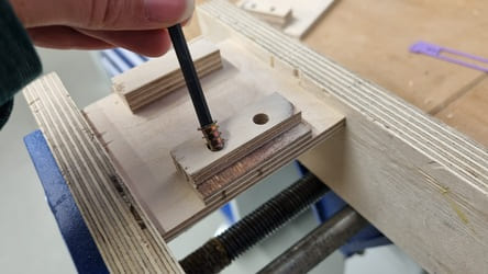
I then drilled a pilot hole then used a forstner bit to drill out the large hole. I started by going from the front of the piece of the wall with the smaller bit all the way through then from the back with a slightly larger bit to accommodate for the nut to hold the plug in place. The left-over piece of wood was about 5mm thick, so I was careful to only take a bit off at a time.
The plugs are keyed, so I was aiming to have them all in the same orientation however it was quite difficult to tighten them, so I gave up in that aspect.
In the future I would allow more leeway around the nut for fingers to hold it in place.
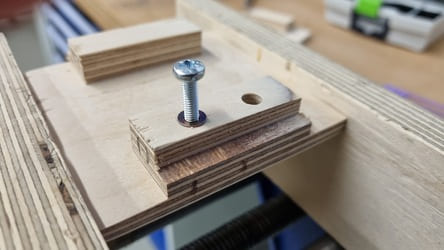
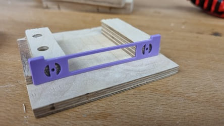
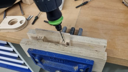
On the base I need to drill the horizontal holes that will connect the front and back pieces to it. I designed a simple 3D model which clips onto the edge of the step and allows me to mark the center and edge of the hole.
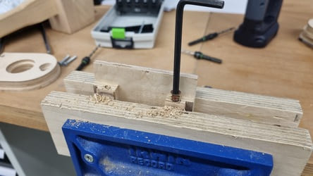
I then drilled out the hole and screwed in 4mm threaded inserts.
I also put in threaded inserts on the top face. Total of 6 threaded inserts per base.
I also put the threaded inserts into the controller.
I glued the flyer together along with the two halves of the controller.
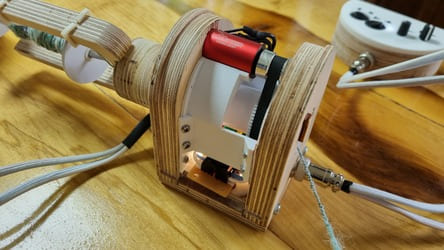
Then I used the dremel to clean up the holes and remove material until the bearings and motor were press fits.
I also used the dremel to finish the plug hole for the controller.
Finishing controller - Laser Cutting
I used the sketch from fusion for the controller as well as the svg for PCB for the controller to create the design for the acrylic cut lid.
It is held in place by the caps of the potentiometers and the top of the switches clicking into place. I had to file it a bit to make sure it lined up as the soldering probably was not exactly straight, so it was just slightly off.