7. Computer Controlled Machining
This week we are using the large router CNC mill to design, mill and assemble something big. Ideally without fasteners or glue.
The project I would like to create is a drum carding machine for wool. This is one of the main steps before you can spin the wool, the focus of my final project.
I have in the past started to design the plan for the carder so adapting them for the CNC mill should be possible.
About the Router
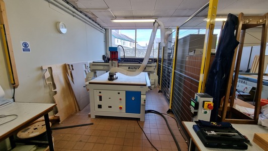
The machine we have is a TechSoft RouterCAM 1224.
We went through the safety and set up of the machine and test on the Group Project Page. Please check that out for a detailed step by step use of the machine and the safety.
Designing the Carder
Commercial Examples
The Ashford brand is big in the wool processing scene, their carder has many of the features I plan to include. Here is an example of a more budget friendly drum carder but it works in a similar fashion.
Features:
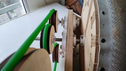
The Majacraft drum carder is an example of a alternative design. Instead of having a drive band it uses gears to transfer the mocement and change direction. I am considering this design as cogs can be easily laser cut.
I had designed a few versions in the past. However these were in the mindset of laser cutting.
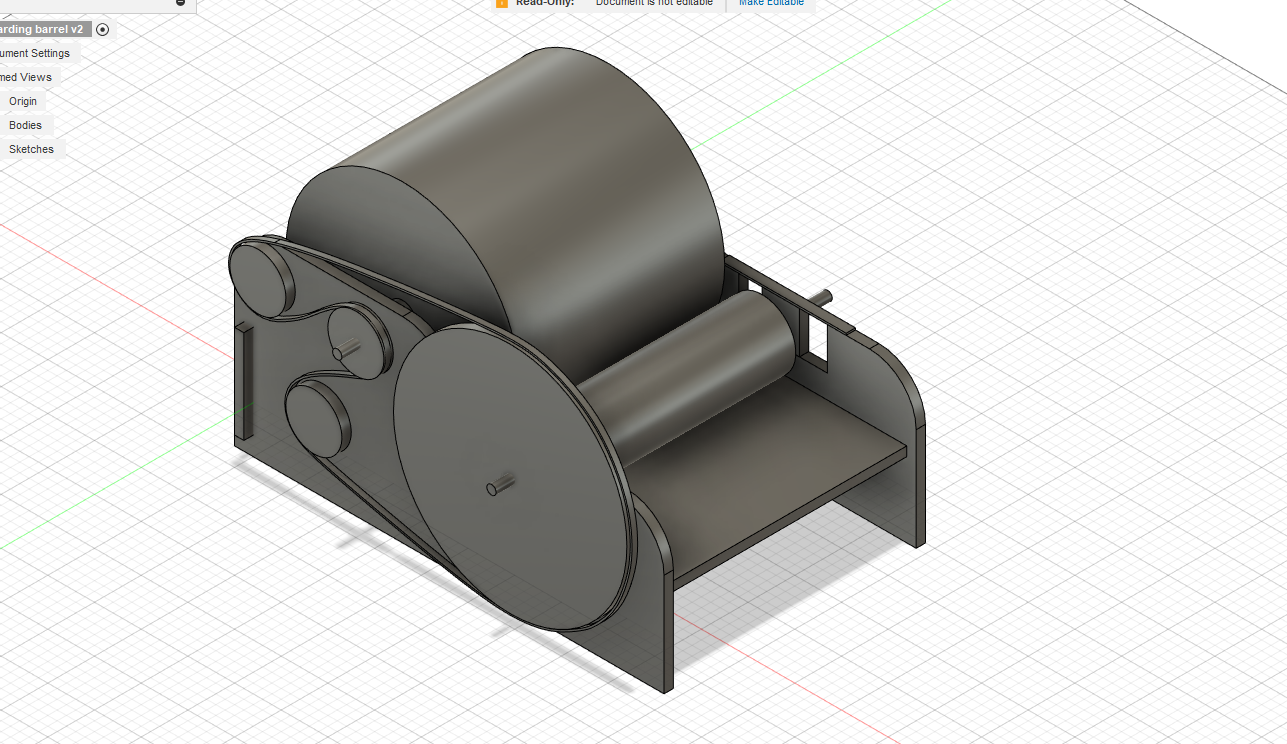

I will redesign it in fusion learning from past designs and some new drawings. Keeping in mind some nice wedge joints and dogbones on cutouts.
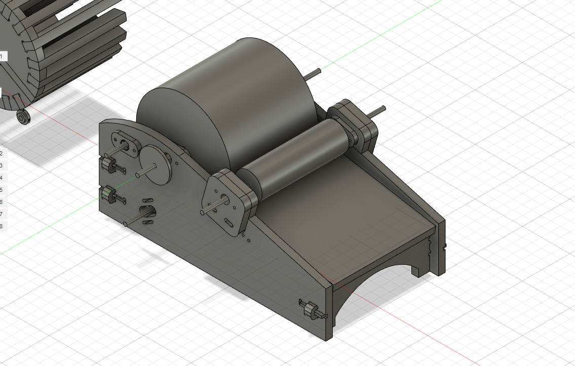
Modelling something that includes so many parts and things to consider was definity a challange, even though I had quite a good base design to go from. There did end up being some mistakes but they were salvagable. I'll go through them in a later section.
After I had the walls designed I layed them out flat to check the amount of wood I need. I used the component and joint feture to do this initially. This demonstrated I'll use roughly a third of a full sheet.
The tooling data was on the fusion for the fablab so I needed to transfer the design files over.
This was a bit of a issue as it was a fusion archive file. I now believe this is because I had imported in other components such as the bearing holders that were not transfered over along with the main file. As a solution I just saved the sketches as DXFs imported them into a new design on the other fusion account and them reextruded and duplicated them to match the design I needed. I also meant I needed to reset up the parametric design and measurements.
This wasn't ideal because I made a mistake and missed some holes on one side which I will need to fix by hand.
Modifications to file following test piece
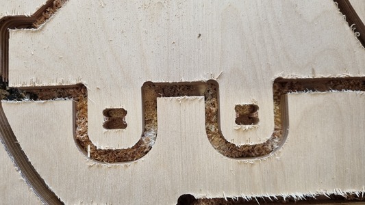
The issues that were present in the test piece were that the shoulders needed 'dogboneing' and to make sure to measure the thickness of the wood accuratly and adjust the parameters in the design.
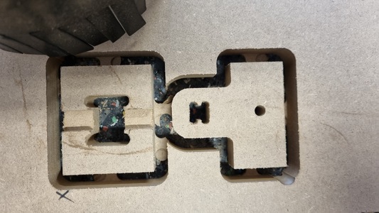
I went through and edited these and also changed the size of the dogbones on the outside cut to be 8.5mm dimaeter to pair with the 8mm cutting.
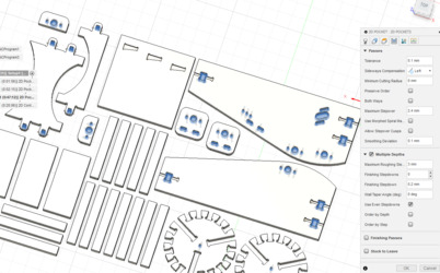
Generating Toolpaths
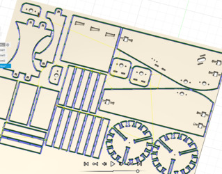
I imported all the moddeled parts into a new fusion file and layed them out to efficiently layout the pieces in the area of half a sheet of ply. Duplicated those which I needed multiple of.
We then go to the manufacture workbench in fusion.
First we do a new set up Aligning the axis to match the bed of the machine (X axis = across, Y = away, Z = upwards) and setting out how much stock we have to mill out of (1220mmx2440mmx18mm).
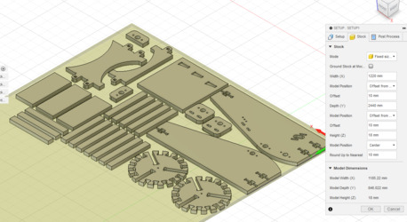
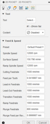
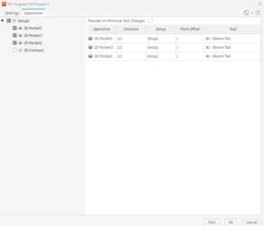
We set up three different pockets jobs for the different heights in the model. These will all be milled using a 4mm flat end mill.
Pocket 1 is the adjustment wedge slots of the back of the input board.
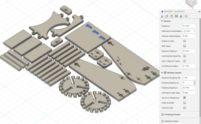
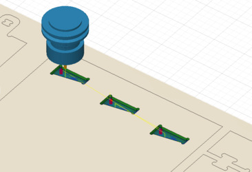
Pocket 2 is the wedge slides on the side of the walls
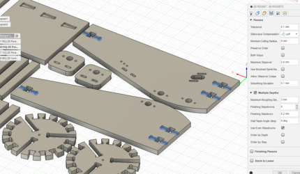
Pocket 3 is a full depth cut of the holes in the parts
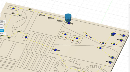
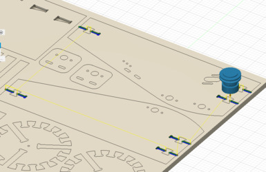
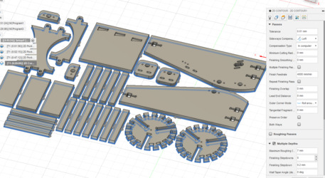
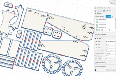
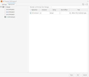
Next the cut out contour job uses a 8mm flat end mill.
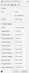
This follows all the edges of the pieces.
This job needs tabs to hold the pieces in place. I relised after the milling the gaps between the slats were too small to have tabs and a wall strong enough to hold everything in place. Could have been an issue and something to be aware of in the future.
Finally we post the jobs selecting the toolpaths we want in each job. We number them 1001 and 1002 to distinguish them whilst in the medallion.
Milling the Carder
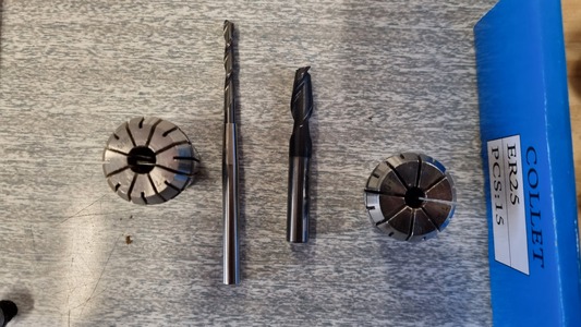
We used a 4mm mill bit for the pockets and a 8mm mill for the contour cut.
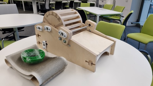
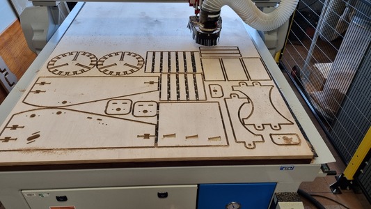
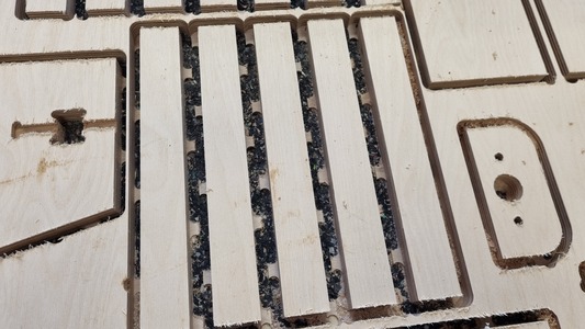
This is the final milled result after hovering the waste.
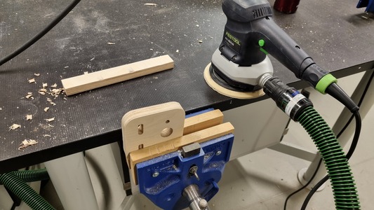
Cleaning the parts
The edges of the parts were quite rough mainly because I stuggled to cut through the tabs cleanly, this ended up with jagged points and some loss of wood.
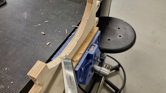
I use a festool rotating hand sander to sand the faces of the pieces. The joints were a bit too tight but with some sanding them could fit nicely.
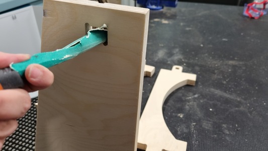
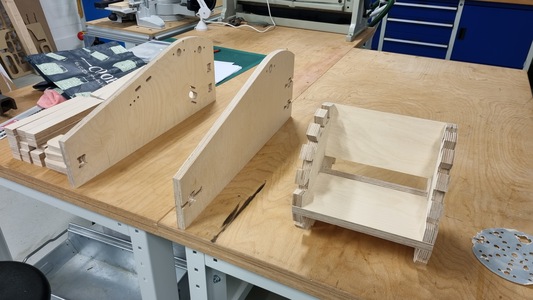
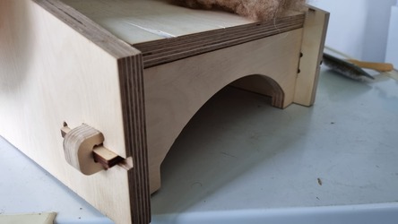
Finished Wedge Joints
Design Issues
When I layed out the design files the slats were too close together, this meant the tabs ended not being attached to any wood. Luckly it didn't case a issue but definitly something to watch out for in the future.
The second issue I forgot to change the size of the dogbones on the joints. Initially the outside cut was going to be using a 6mm tool, however we swapped to a 8mm tool. I forgot to change these.
The hole in the center of the barrel also ended up at 6mm instead of 10mm for the bar.
One of the walls didn't have its set of sliding holes for the adjustment of the small drum position.
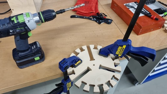
I went through and fixed these problems by hand using drills and files.
Creation of Extras
Parts to buy
Some components I needed to buy in are:
3D Prints
There are a couple of parts which needed to be modelled and 3D printed.
Laser cut parts
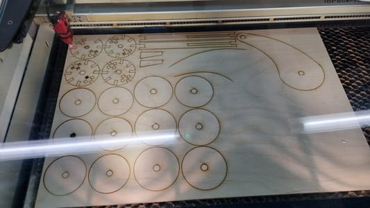
Some parts were too small or needed thinner wood which would be easier to laser cut.
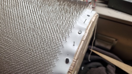
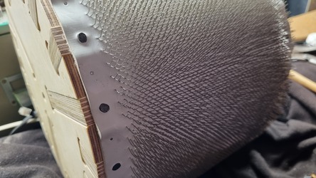
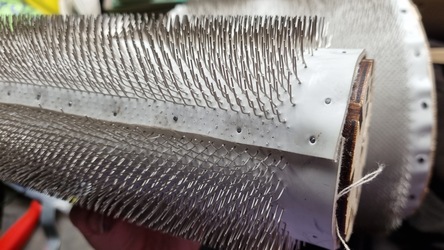
Attaching carding cloth
I brought a meter of carding cloth from Headgehog Equipment which is deffinitly the most expensive part of the build. Because of the price I did not by extra which was infortunate as I did not take into consideration that the circumference of the drum isn't quite enough fabric as it is quite thick to it requires extra length. Fortunatly a gap isnt too much of a issue.
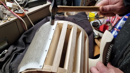
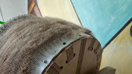
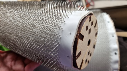
We used a mixture of carpet tacks and vinyl nails to hold it down on the drum. It required two people to make sure it stayed streight. It wasn't possible to stretch the fabric to keep it tight, it was better to actually consentrate on keeping it streight and accept that there will be ripples along the edge. The fabric stayed taught in the middle of the drum.
For the small drum we added a piece of wood in the gap of two of the slats to have a strong surface to attach the main joint of the fabric. It we went streight into the lasercut ply it would likely split it.
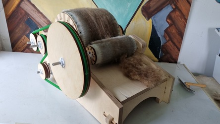
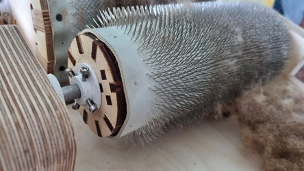
Final result
Here is the final result with the drums mounted on the cut steel and all the 3D printed parts in place.
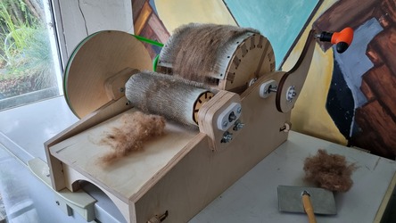
You can see the fibers hooked into the fabric.