10/11. Mechanical Design & Machine Building
For this project the majority of the work was 3D modelling the machine and making sure all the parts fitted.
Requirements to consider
The part of this process that I struggled with is that there are a lot of different things to consider which interact with each other.
Design process
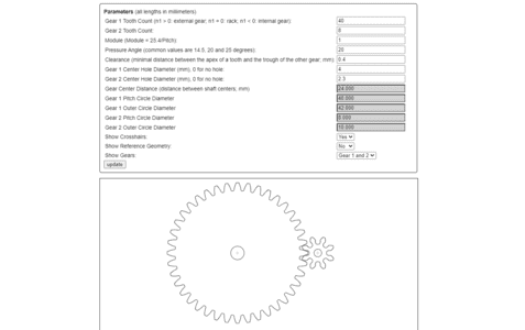
I started by using a Gear Generator which allows you to adjust some basic values and then download either a DXF or SVG. This then can be imported into fusion 360
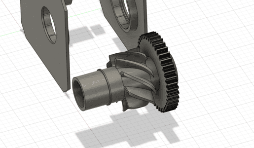
I set the ratio of teeth to be 8:40 which gives me the reduction by a devision of 5.
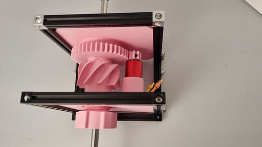
I built everything around the gears to ensure everything would be central and line up. To begin with I had not scaled up the gears enough which caused the motor to interfear with the drum so I scalled it it further.
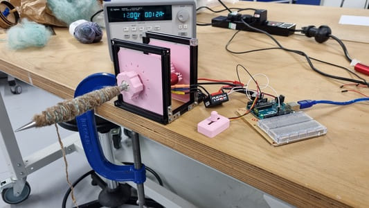
I modelled a representation of the motor bassed on the schematic sizes. This worked great on the whole but when the motors arrived the wires came out the back of the motor. This caused some issues as the motor was mounted from the back on the wall. I ened up widening the whole machine so that there would be pace for the wires to sit inside the wall.
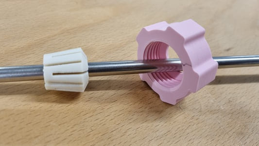
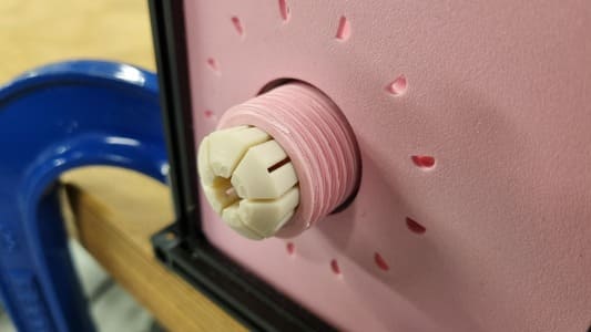
The model featured a collet system which tightened down on the knitting needle to fasten it into place securely. I think this was possible as the needle was large at 8mm diameter. For smaller aplications I would be concered the walls would be too thin to hold enough strength. I did end up pritning the collet out of ASA plastic which is more flexible than brittle PLA. However it would only be clear the durability difference with long term use.
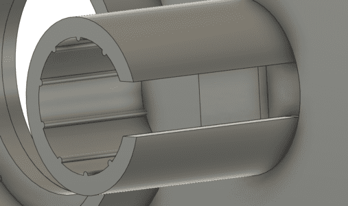
To begin with the taper within the drum was a perfect length for the collet to sit inside. However this made it difficult to tighten down the nut and taking a closer look at the CNC's collets they also did not slide in fully. Therefore I created a second version which caused the callet to fit in a rough maximum of 2/3rds.
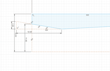
You can see the construction lines representing the collet angle whilst i was making the sketch to revolve.
The bearings needed to be press fit within the walls. The wall should only touch the bearing casing, the wall on the drum should only press against the inner bearing races.
This took a few test prints to get things right.
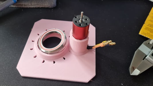
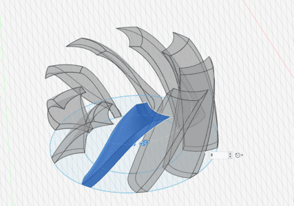
There was some concern of the motor heating up so I designed some fan blades to side on a unused part of the drum which would stir the air around within the casing and some air holes on the front face.
I used a handy tutorial by getprototyping on youtube to design my own fan blades.
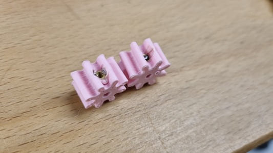
The small gear had to be fixed to the motor. To do this I made a hole which a heatset thread could be placed. The heatsunk thread was for a m2 screw but I made a 3.5mm hole for it to sit within.
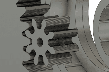
The gear was right on the edge of being thick enough for this. Initially I used m2 4mm length threads however this was too long, but he m2 3mm worked with a 5mm screw. It took a couple of attempts.
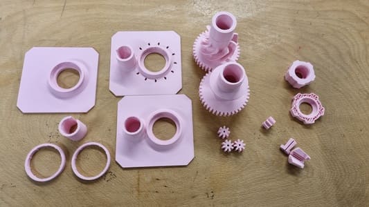
Here are the old version prints
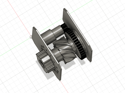
Here is the final model:
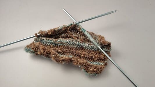
I am pleased with how it turned out. There are difintly some improvements that could be made but it works successfully to do some spinning.