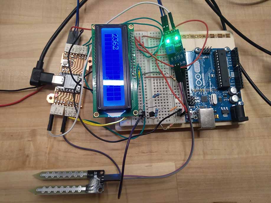
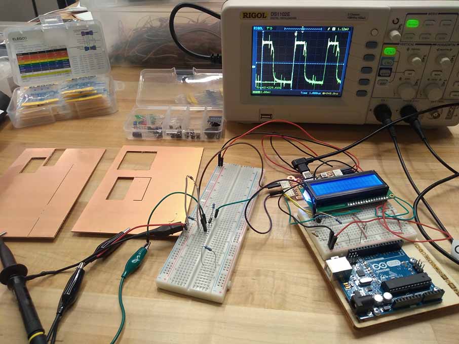
For my first attempt at making the capacitance-based sensor, I took inspiration from the wiring Neal showed in his lecture for this week. On the oscilloscope I could see that there was some reaction to moving objects near the copper plates, but very little. Large reactions only occurred when moving the plates or touching them at the same time.
Here is the code that I used: [download ]
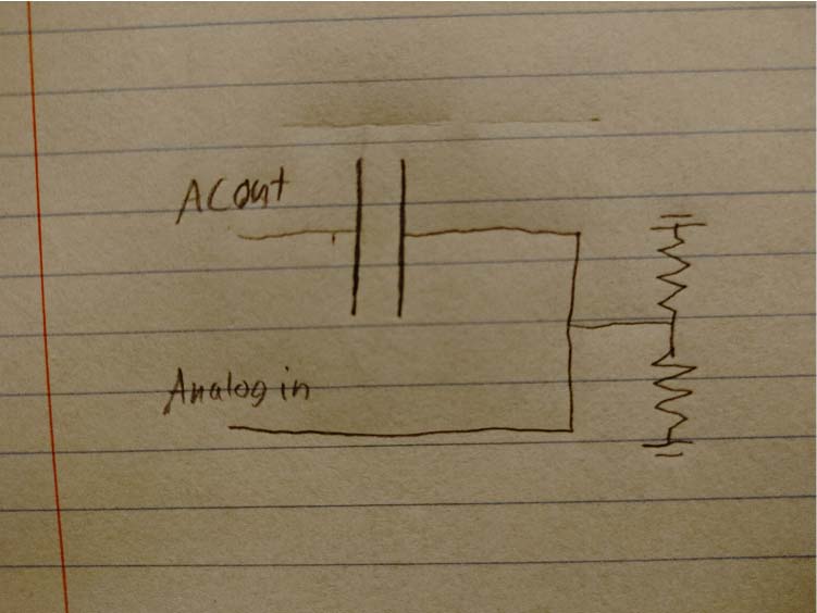
The code sends a square wave into one plate of the capacitor and then finds the highest peak value and trough value for the voltage induced in the other. These values should show the capacitance between the plates.
To see how to wire an LCD screen like the one I used, see my week 4 documentation.
Week 11: Input devices.
This week I attempted to make a capacitance moisture sensor, and used an oscilloscope to measure signals from different sensor wirings. When I failed to get my sensor fully functioning, I settled for a simple resistance based soil sensor. I also worked in a group to measure the resistance changes in a thermistor, and a light based resistor. I learned to use thermistors in circuits to detect when something is overheating. The group documentation can be found here. I used my development board from week 8 for this week.
Capacitance based sensor
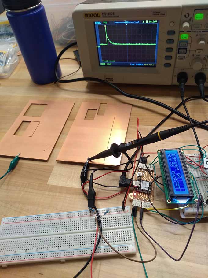
I displayed values read from the plate on an LCD to try to get a sense of how well I was reading it. I found that due to the very low voltage and short timescale, the sensor had very low sensitivity to anything that I was interested in measuring. My code involved storing the highest and lowest values observed in the time proceding each switch in voltage.

For my third attempt at making the sensor work, I tried to copy the circuit diagram of a popular capacitive moisture sensor that I found online. This ran into a curious problem where the square wave signal was only properly generated when I didn’t print anything to the LCD screen. This seemed like a nonstarter and I was running out of time so I switched direction after this.
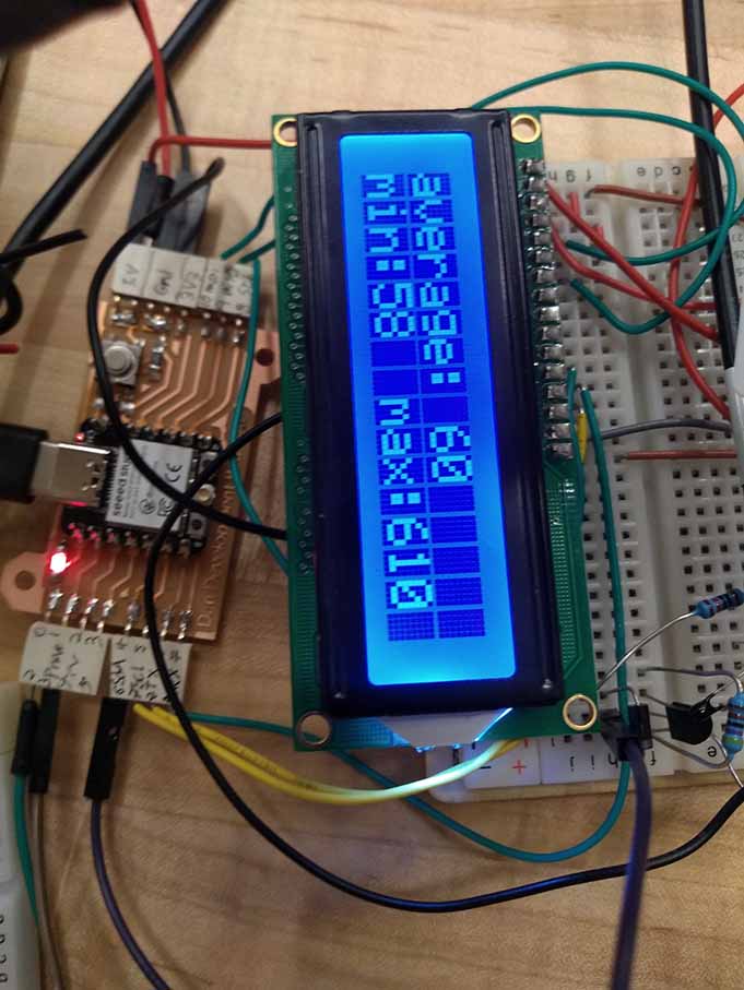
Resistance sensor
I decided to try a pre-made resistance based soil moisture sensor instead. This was trivial to set up, though I don’t think that it will work for my final project. I displayed the analog read output from the sensor on the LCD, showing the real time resistance across the sensor.
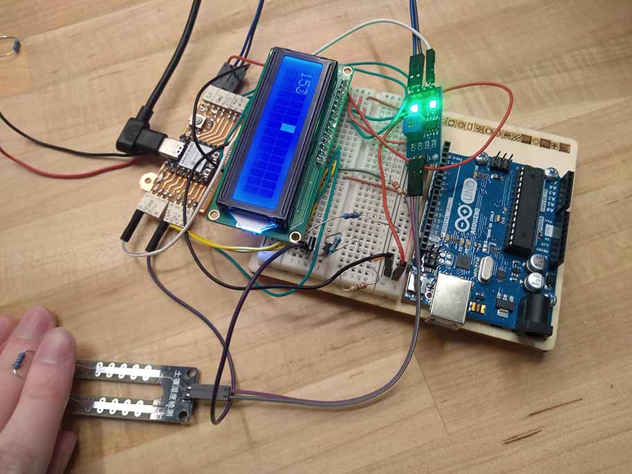
Here is the code: [ download ]
It simply reads the analog value from the sensor and prints it to the LCD.
        #include
        LiquidCrystal lcd(9, 10, 8, 20, 21, 7);

        int sensor = 2;

        void setup() {
          lcd.begin(16, 2); // Set up the number of columns and rows on the LCD.
          pinMode(sensor, INPUT);
        }

        void loop() {
          lcd.setCursor(0,0);
          lcd.print(analogRead(sensor)); // Displays the reading from the sensor
          lcd.print("   ");
          delay(100);
        }
The analog signal value correlates with the level of resistance across the sensor. I don't know what the numerical values I received mean in terms of actual resistance values, but the value certainly decreases when the resistance is lowered. When put in soil, the sensor should give a lower reading when the soil becomes damp.