- Assignments
- I2S Microphone
- Step response
- Capacitive sensing
- Phototransistor
- Thoughts on the XIAO boards
- Group assignment
- Files
- Lecture notes
- Erwin’s lecture
- Physical things to measure
Input Devices

This week was all about capacitive sensing, I2S microphones and me being upset at the XIAO boards.
Assignments
| Progress | Task |
|---|---|
| Done | Group assignment: probe an input device(s)’s analog and digital signals |
| Done | Individual assignment: measure something: add a sensor to a microcontroller board that you have designed and read it. |
| Done | Documented what you learned from interfacing an input device(s) to your microcontroller and how the physical property relates to the measured results |
| Done | Documented your design and fabrication process or linked to the board you made in a previous assignment. |
| Done | Explained the programming process/es you used. |
| Done | Explained any problems you encountered and how you fixed them. |
| Done | Included original design files and source code. |
| Done | Included a ‘hero shot’ of your board. |
I2S Microphone
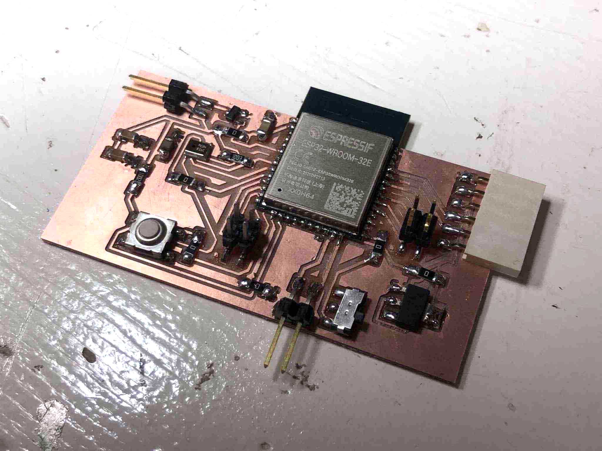
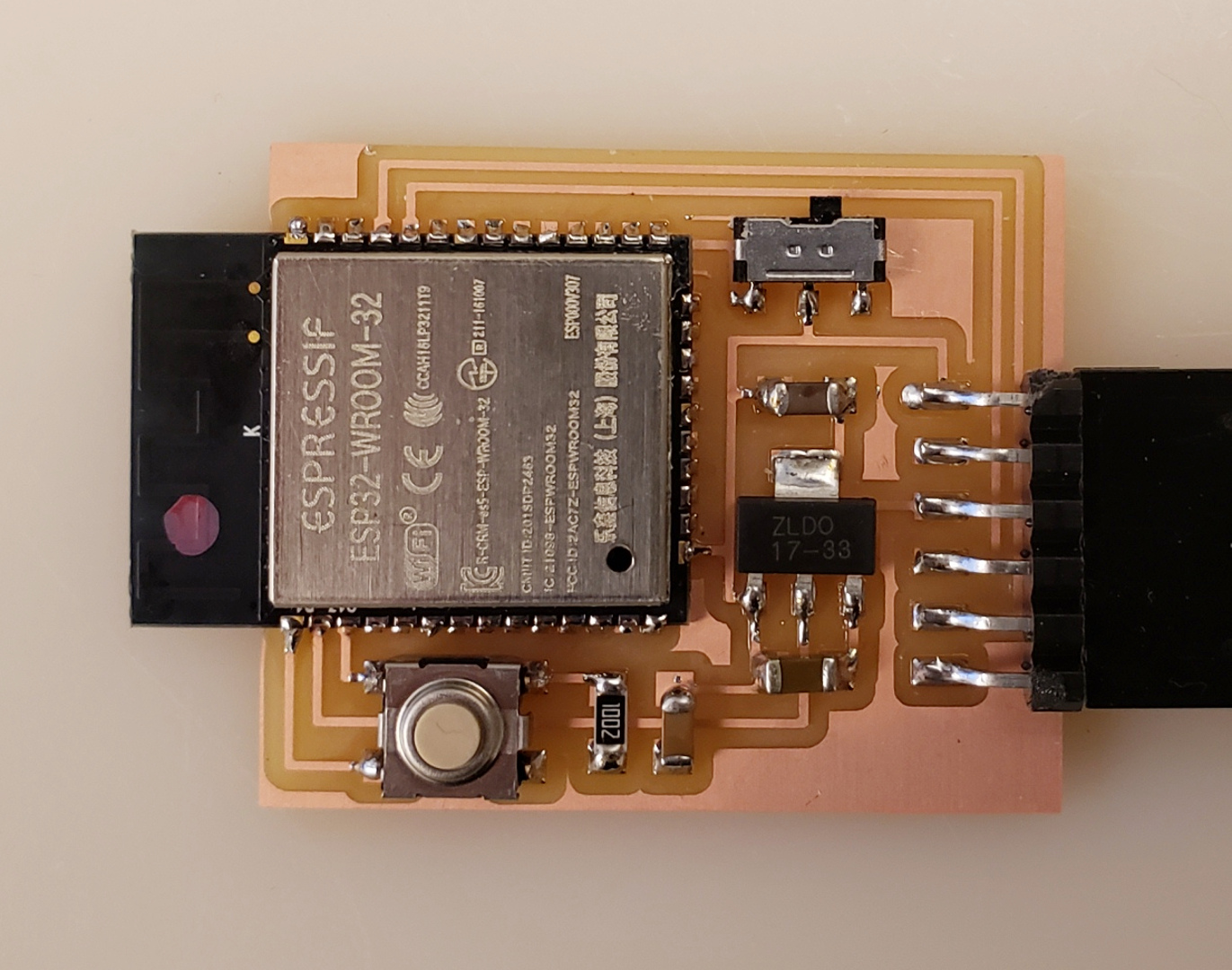
For this week I wanted to try out I2S with the I2S digital microphone in the fab inventory. For this I’ll use an ESP32 WROOM with MEMS microphone and I2S and combine it with a speaker as output device. I also want to connect other pins to header pins so it’s also a development board, and I don’t have to make as many boards from scratch. I wanted to do something like this during output devices week but I just got very confused about what I was doing. This week was no different, and it was even more frustrating.
Reference boards
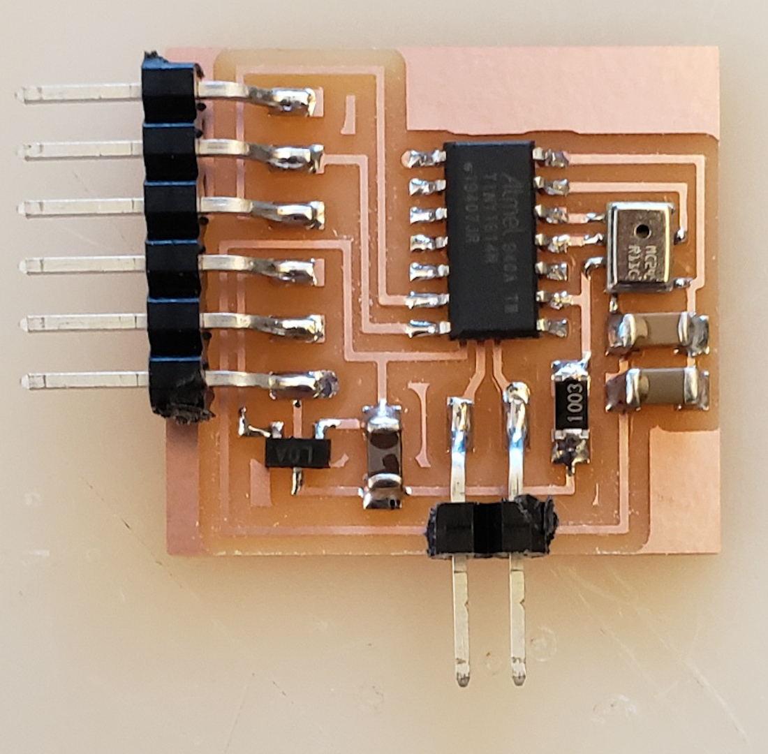
On Friday morning I started designing the board in KiCad with this ATtiny 1614 board by Neil as reference. The ATtiny doesn’t have I2S but Neil simulates I2S in software by bitbanging. I want to use an ESP so I can make use of it’s I2S capabilities and don’t have to worry about bitbanging.
Note:
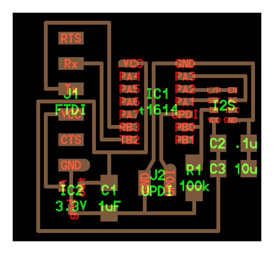
- Filtering out low frequencies with the high cap (C3) and the high frequencies with the low cap (C2) for a cleaner signal; C1 is for voltage fluctuations on the power supply; in the case above it’s a voltage regulator that regulates power provided by the FTDI. As seen in the datasheet for the microphone:

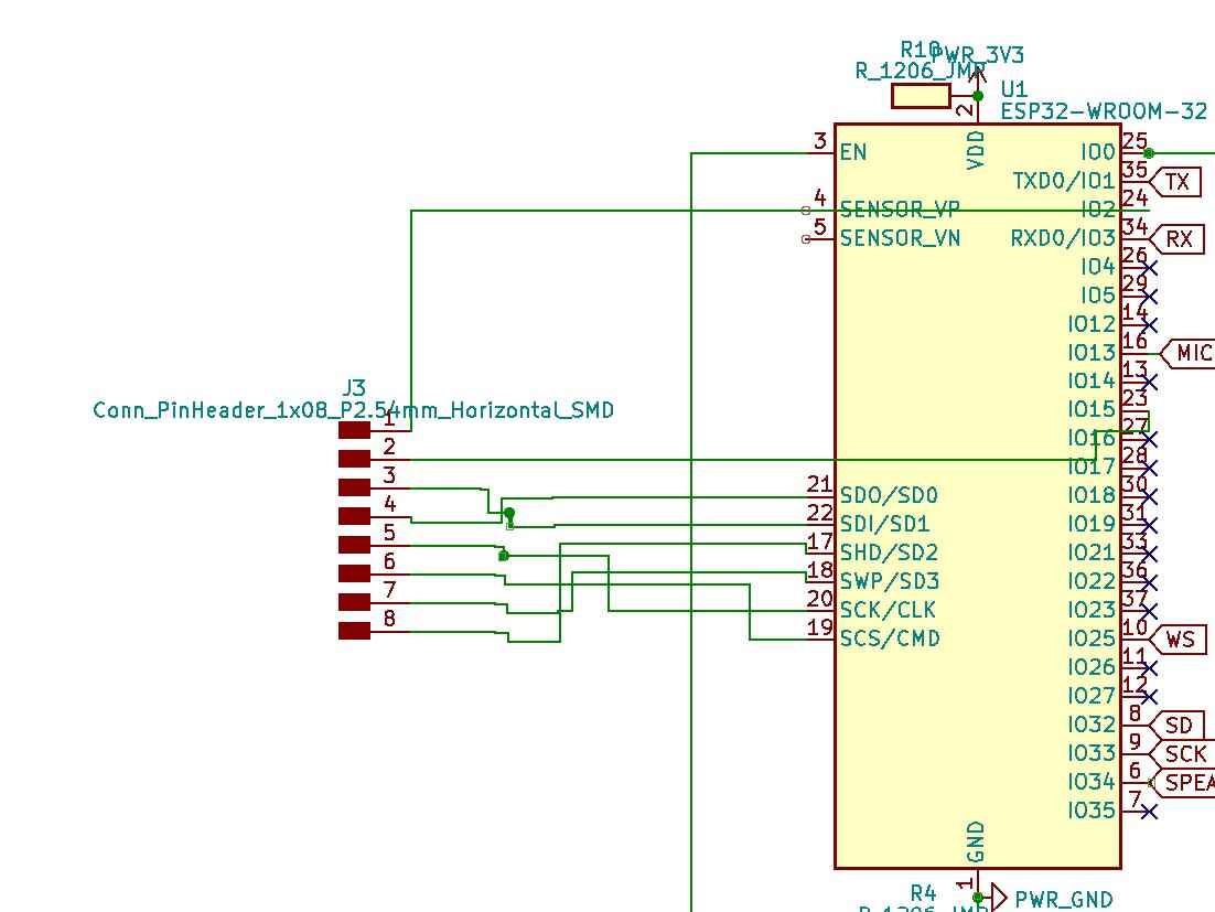
This ESP32-WROOM board is my reference to make sure I can program the board:

Pin-out ESP32 WROOM:

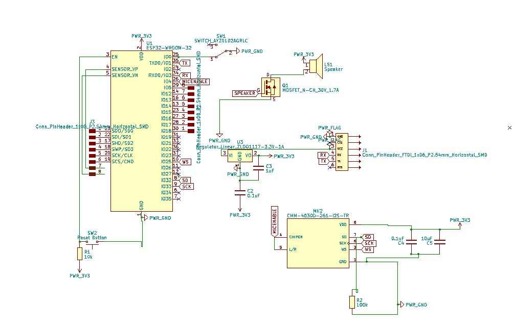
KiCad
I started out in EESchema with connecting all of the components. This part was a nightmare because the schematic symbol for some of components have barely any relation with their footprint. This also goes for the ESP WROOM. I had to reconnect the traces many times because I would find out in the PCB editor that everything was crossing. I have never spent so much time trying to figure out a rat’s nest. I asked Kris (the one maintaining the KiCad fab library) why the symbols and footprints don’t match up.
- I couldn’t find the footprint for the microphone in the fab library so I downloaded it from SnapEDA
- EN is CHIPEN is chip enable; whether microphone is on or off. If you connect it to an input pin you can turn it off or on.
This was my first attempt at the schematic:

And the corresponding rat’s nest:

I moved the parts around and started to route them, but it was absolutely impossible. I removed one of the row of header pins to make my life easier, but I think it’s kind of a waste to not be able to use those pins; I don’t want to solder many ESP-WROOMS (tiny pins) so if I can make this into a working development board that I can add modules to that would be great.
After like 5 hours and starting over again and again, I got most of the parts wired but I had removed all of the header pins which pissed me off so I stopped out of frustration.
The next day I decided to give it another go. I added a bunch of zero Ohm bridges and managed to wire something; not all pins are used but still plenty are. PCB editor doesn’t understand the 0 Ohm bridges fully though because it keeps drawing a white line between the pads of the resistors. I ignored it.
Of course after this I found out from the datasheet (and from the back of the chip) that most of the pins at the bottom row are actually not connected. In EESchema there wasn’t a mention of it so I didn’t realize and I think it’s weird that a chip would have so many pins unconnected. Pin 17-22 are not connected:
I removed the header pins and added two 2x02 headers added to some of the GPIO pins (keeping in mind where the analog pins were because I want those especially).
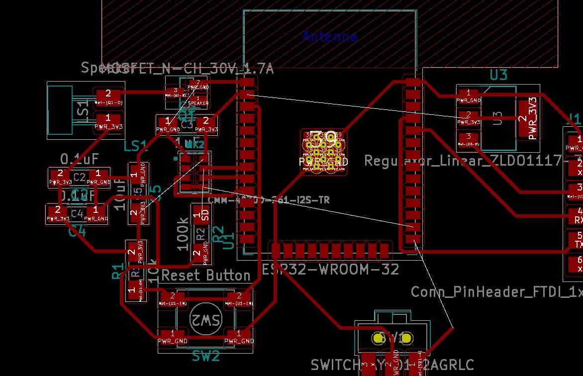
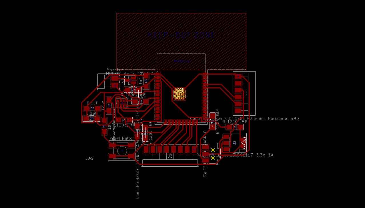
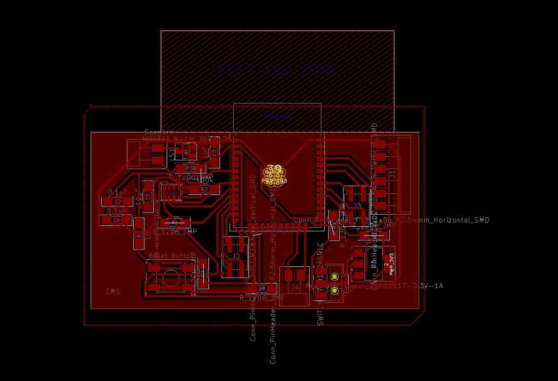
I did a design rules check, which was a nightmare. It’s not possible to work with the ESP Wroom and not violate the clearances because the pads are too close together. I already decided to trick the milling machine here and set the diameter of the milling bit to a value lower than 0,37mm. Other errors involved those ground holes in the middle of the footprint of the ESP, and errors because KiCad doesn’t understand how the 0 Ohm bridges work.

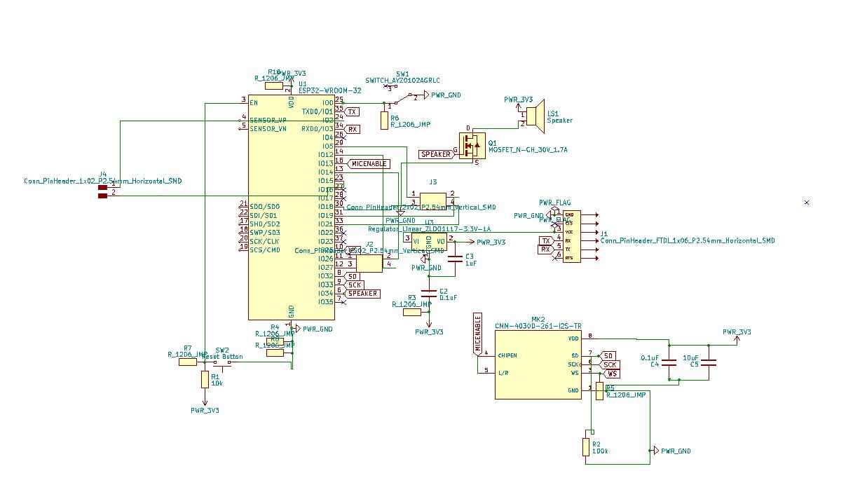
Final board in the PCB editor:
And the messy schematic after all of the changes:
Milling and soldering
To prepare for milling I removed the weird ground pad and fixed the circles for the switch. Before and after:
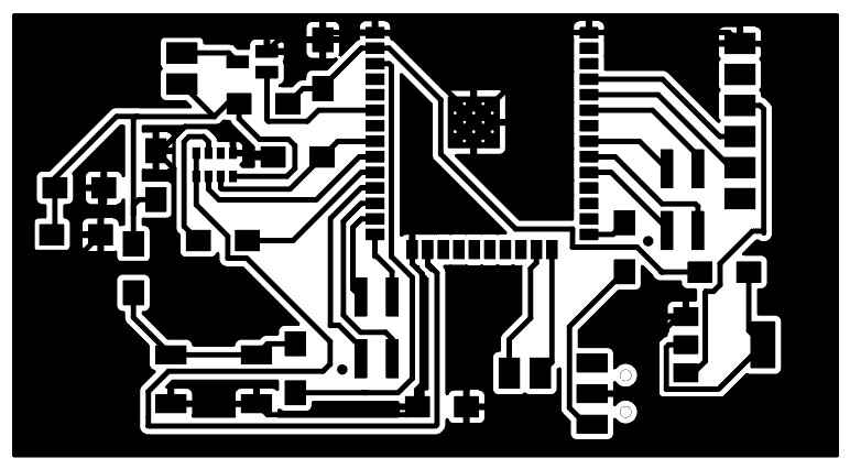
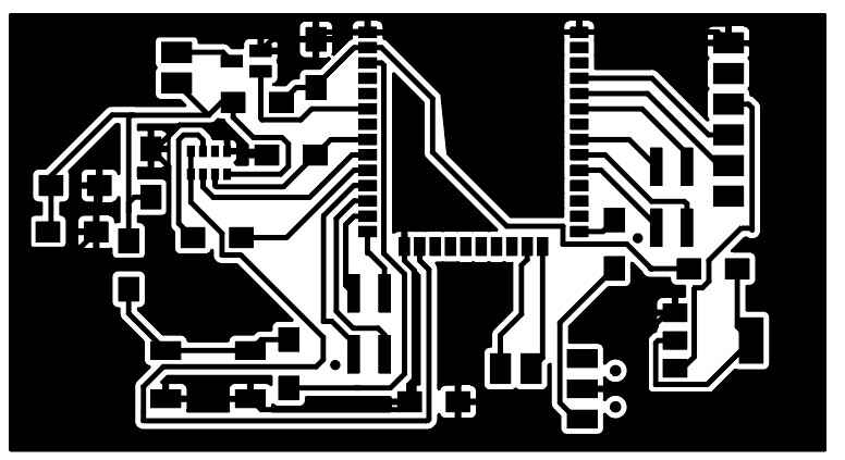
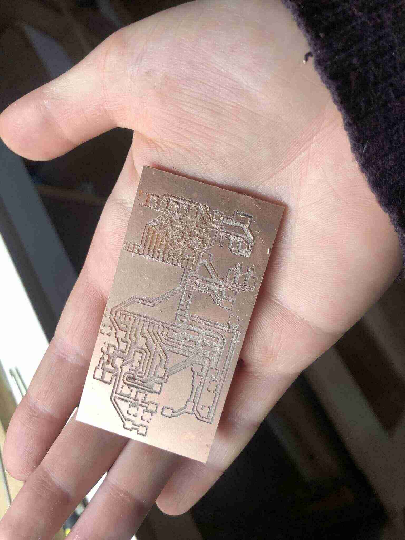
As mentioned before, I set the diameter of the milling bits for the traces to 0.369mm so I would get the correct paths in mods. Milling went fine:

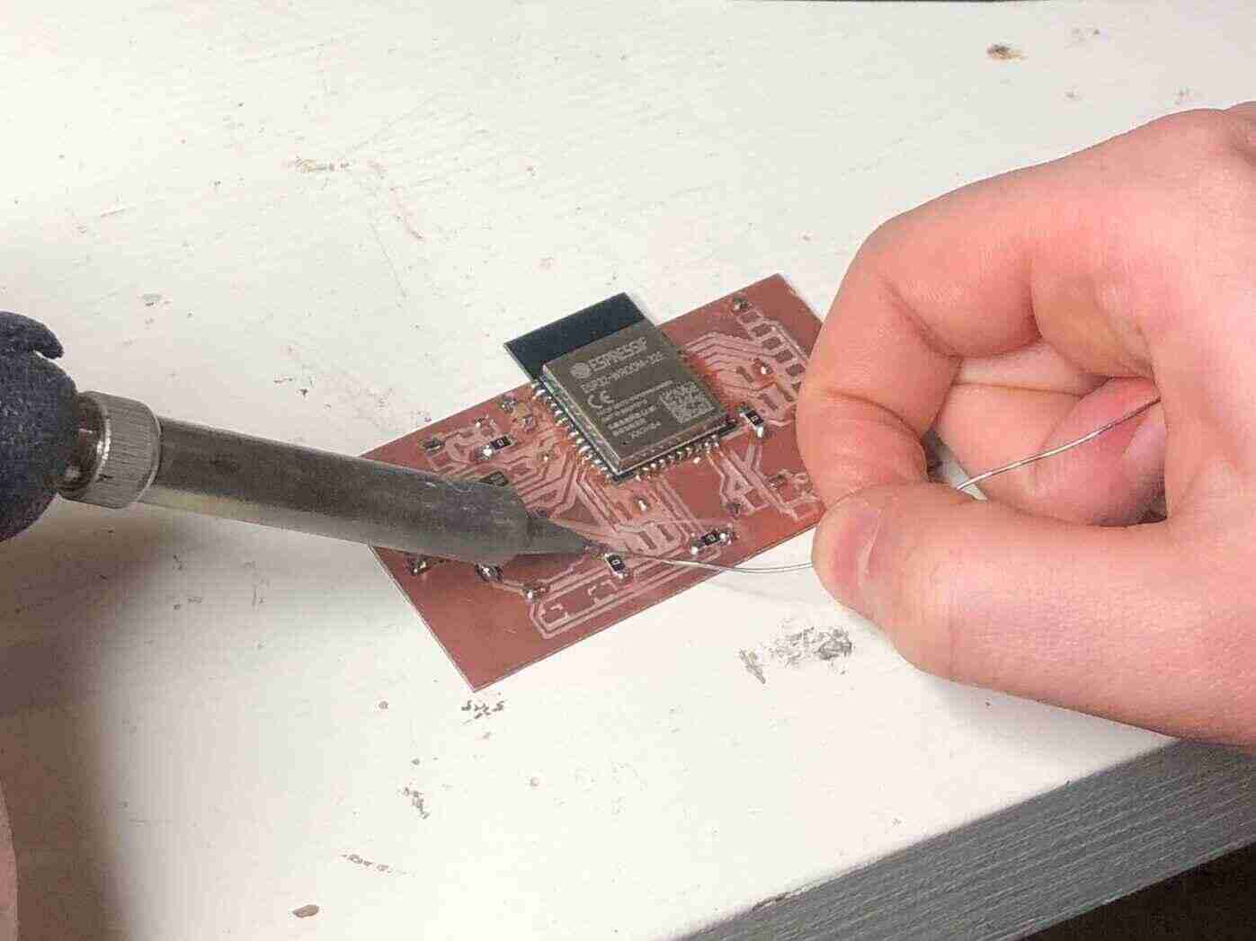
I started with the ESP to get that out of the way. Then I improvised a reflow method with solder and a heat gun, because I didn’t know how to do reflow yet and Henk wasn’t in the lab. This was probably not the best idea.
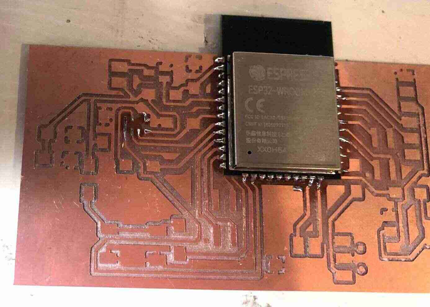

Then I did all of the other components which went fine.
Programming
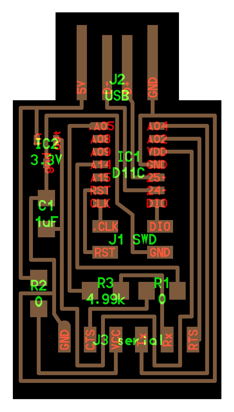
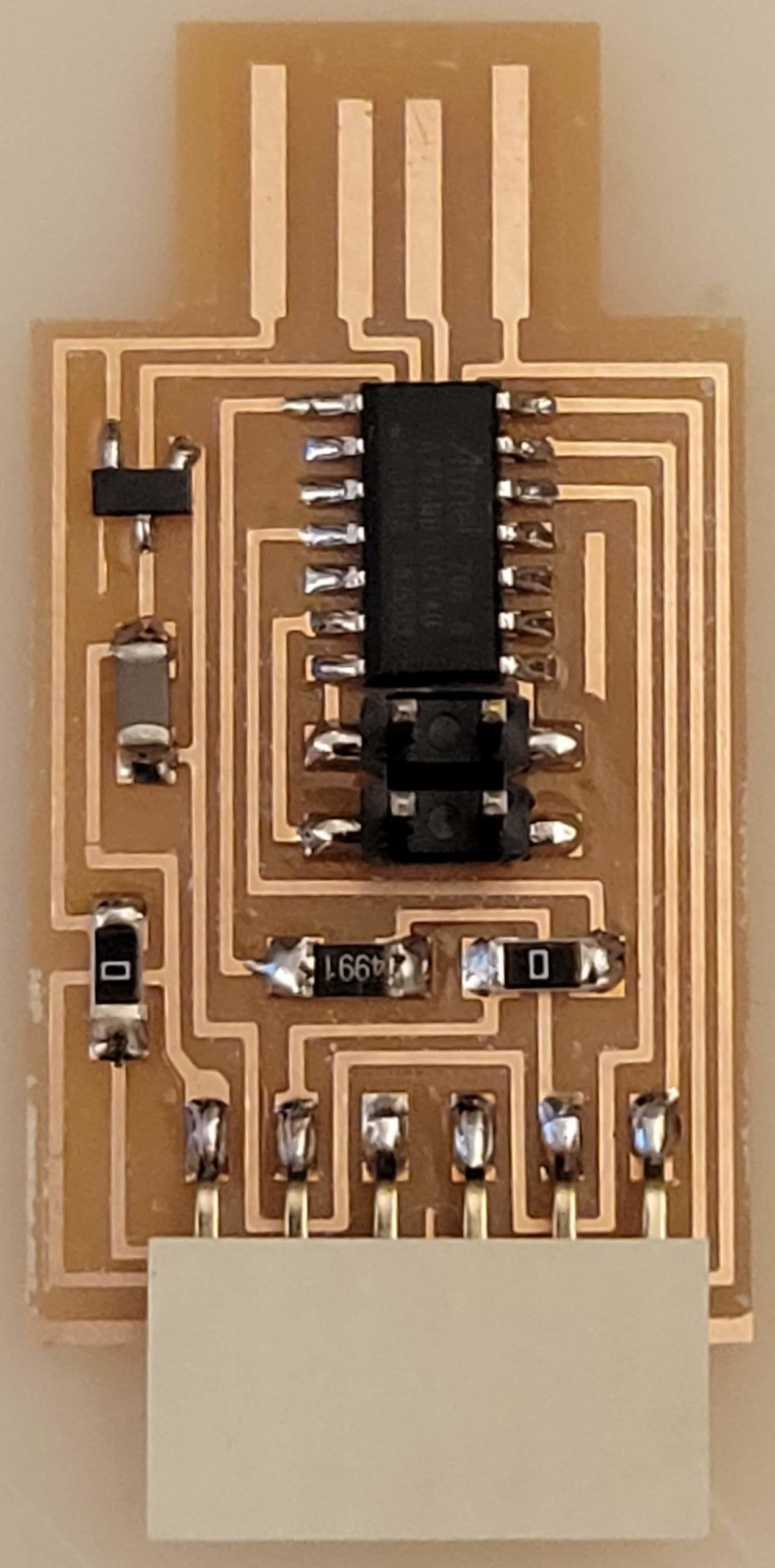
I couldn’t program it before Tuesday because I didn’t have the correct programmer, and I wasn’t really sure which one I needed anyway. On Tuesday Henk told me I needed the hello.D11C.serial board based on the ATSAMD11C, and program with a FTDI cable (or any wires in the right order).
I tried to program the ESP WROOM with the programmer Henk gave me, but I got this error:
esptool.py v4.5.1
Serial port COM34
Connecting......................................

A fatal error occurred: Failed to connect to ESP32: No serial data received.
For troubleshooting steps visit: https://docs.espressif.com/projects/esptool/en/latest/troubleshooting.html
the selected serial port For troubleshooting steps visit: https://docs.espressif.com/projects/esptool/en/latest/troubleshooting.html
 does not exist or your board is not connected
I tried all kinds of variations in the setup but I kept getting this error. One thing that differed for me in comparison to Neil’s programming method is that he uses AVR ISP while I use esptool because that was the only option that was visible for me, but according to Henk it didn’t matter.
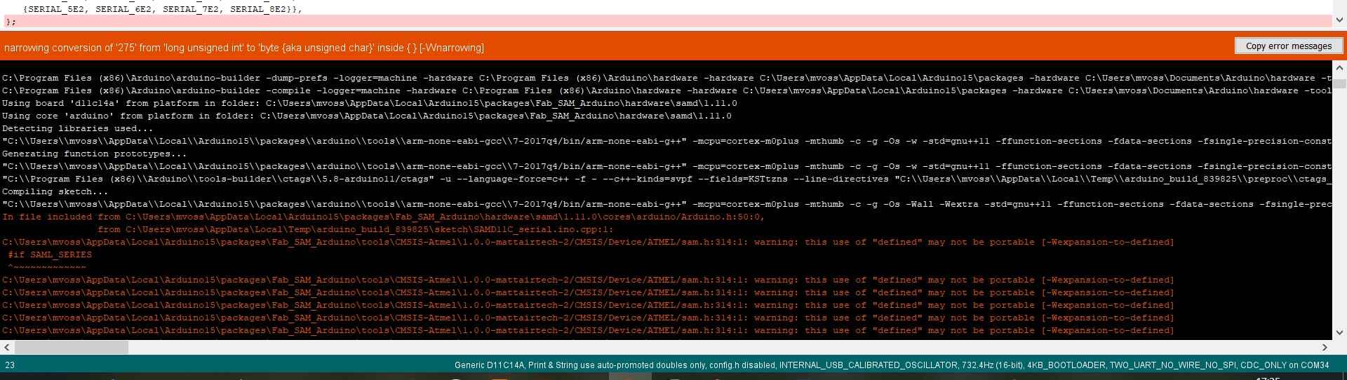
Henk told me to follow these steps to make sure that the programmer was programmed, but there I also ran into trouble summarized by narrowing conversion of '275' from 'long unsigned int' to 'byte {aka unsigned char}' inside { } [-Wnarrowing]. Henk sent the error to Quentin; since on his computer it worked fine he uploaded the code to the programmer.
Next I tried to follow Neil’s steps again but I got this error:
esptool.py v4.5.1
Serial port COM25
Connecting...

A fatal error occurred: This chip is ESP32-C3 not ESP32. Wrong --chip argument?
A fatal error occurred: This chip is ESP32-C3 not ESP32. Wrong --chip argument?
So I changed it to ESP32-C3 Dev Module and the code uploaded succesfully, but then I realized that I accidentally uploaded to the XIAO ESP and my board wasn’t connected at all.
RX and TX
Then I tried with the correct board and ESP32 Dev Module as board, and it still didn’t work (no serial data received). Then Henk asked me if RX and TX were connected correctly and I told him that I connected RX to RX and TX to TX; while saying that I realized that that was wrong so I flipped the wires and then it worked!
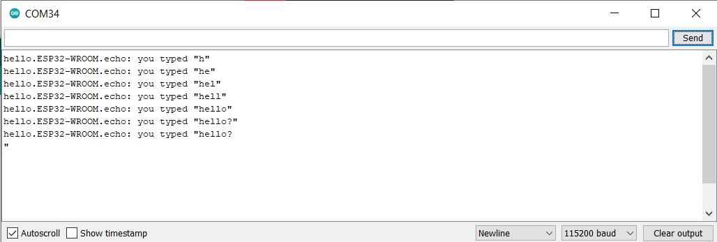
I flipped the switch from prog to run and pressed the reset button on my board. I opened the serial monitor and sent something and my board responded! I’m very happy.
Remember:
- Press button during code upload
- Switch flipped away from chip is program mode and switch flipped towards the chip is run mode
-
Press button again to run
- All programmers can be found here
- Video by Neil on programming the ESP32
Microphone
I uploaded the code from here and added a digitalWrite(13, HIGH); to the setup to enable the mic (hopefully). That didn’t show any audo signal. I resoldered a new mic on but that didn’t help either (I think I shorted two tracks). Then I saw that I switched SD and SCK in the code so I fixed that, but it still didn’t show any audio picked up.
I also tried the code from here. The only things I changed were:
#define I2S_MIC_SERIAL_CLOCK GPIO_NUM_33
#define I2S_MIC_LEFT_RIGHT_CLOCK GPIO_NUM_25
#define I2S_MIC_SERIAL_DATA GPIO_NUM_32
And the serial.printf changed to Serial.print(raw_samples[i]); because it was throwing errors.
The only thing I could see was one big line of zeroes so that didn’t look promising. I checked the wiring, measured the entire board, double checked the pins, but nothing seemed off.
Walking through these steps from Espressif and these steps from Arduino here the library used.
int begin(int mode, int sampleRate, int bitsPerSample)
- only supported sampleRate is 16000
- only supported bitspersample is 16
I2S location on my computer (for my own reference): C:\Users\mvoss\AppData\Local\Arduino15\packages\esp32\hardware\esp32\2.0.7\libraries\I2S\src
Default pins in I2S.h for ESP32 are like this; I changed the SCK and SD pins to the pins used. FS is the same as WS. you can also define them in the Arduino code like this: int setSckPin(int sckPin) (same conventions for different names). These are the values used:
PIN_I2S_SCK 14 >33

PIN_I2S_FS 25

PIN_I2S_SD 26 > 32

PIN_I2S_SD_OUT 26

PIN_I2S_SD_IN 35
Code
#include <I2S.h>
const int buff_size = 128;
uint8_t buffer[buff_size];

void setup() {

  // Open serial communications and wait for port to open:

  // A baud rate of 115200 is used instead of 9600 for a faster data rate

  // on non-native USB ports

  Serial.begin(115200);

  while (!Serial) {

    ; // wait for serial port to connect. Needed for native USB port only

  }
  I2S.begin(I2S_PHILIPS_MODE, 16000, 16);
  // start I2S at 8 kHz with 32-bits per sample
  // Init in MASTER/controller mode: the SCK and FS pins are driven as outputs using the sample rate
  if (I2S.begin(I2S_PHILIPS_MODE, 16000, 16) == true) { //Officially supported operation mode is only I2S_PHILIPS_MODE on ESP32
    Serial.println("I2S initialized");

  }
  if (!I2S.begin(I2S_PHILIPS_MODE, 16000, 16) == false) { //Officially supported operation mode is only I2S_PHILIPS_MODE on ESP32

    Serial.println("Failed to initialize I2S!");

    while (1); // do nothing

  }
}

void loop() {

  // read a sample
  //  Serial.println("test");

    int sample = I2S.read(buffer, buff_size);

    if (sample) {

      // if it's non-zero print value to serial

      Serial.println(sample); // this just returns the buffer size which is 128

  }
}
What this does is just print the buffer size to the serial monitor; it doesn’t print whether it’s initialized or not. To be continued.
Speaker
I also tried to connect a speaker and play sounds with a tone function, but no sound came out either. I attached it to the oscilloscope, and it didn’t detect when played the tune nor when I did a digitalWrite(34, HIGH) to pin 34. A multimeter indicates a voltage of .1-.3V so that is not correct.
When opening the serial monitor I got a continuous stream of messages like this:
E (2236) gpio: gpio_set_level(226): GPIO output gpio_num error
With this code:
void setup() {
  Serial.begin(115200);
  pinMode(34, OUTPUT);
}


void loop() {
    digitalWrite(34, HIGH);
    delay(1000);
    digitalWrite(34, LOW);
    delay(1000);
  }
}
After looking up this error, I found someone here that had a similar error. In the first line of their error was written E (345486) gpio: GPIO can only be used as input mode so I checked the datasheet again and learned that I picked one of the few pins that only works as an input pin. That explains the lack of voltage detected. It’s annoying because the pin is still called an IO pin in the pinout.
Then I realized that I forgot to break out any power options so that’s really stupid since my whole goal of also using it as a development board is kind of thrown out of the window now.
Notes
| MEMS digital microphone CMM-4030D-261-I2S-TR | https://www.digikey.com/en/products/detail/cui-devices/CMM-4030D-261-I2S-TR/13164051 | voltage 1.8-3.3V |
| Mosfet | https://www.digikey.com/en/products/detail/onsemi/NDS355AN/458899 |
Speakers:
- https://fab.cba.mit.edu/classes/863.22/Harvard/people/Noy/week8.html
- http://fabacademy.org/2018/labs/fablabkochi/students/jacob-jose/week11.html
I saw this in the ESP C3 datasheet, which confused me even more about I2S:
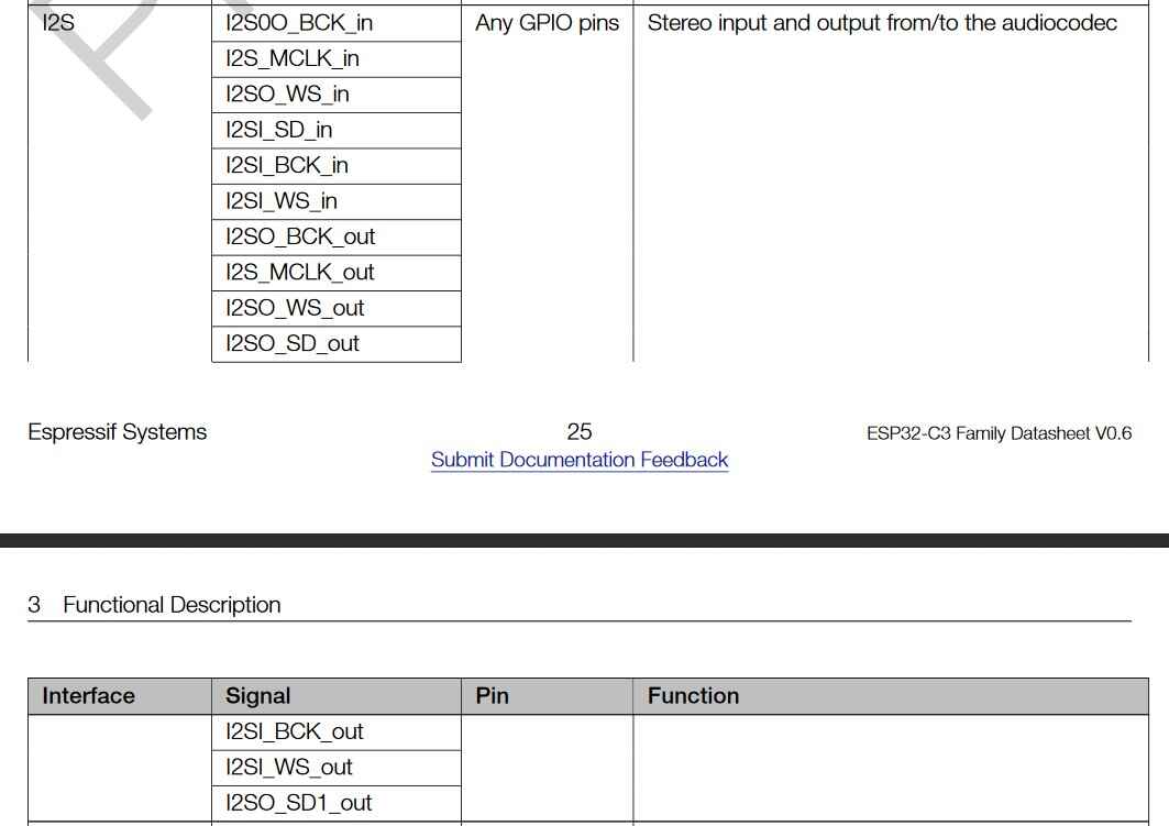
- Programmable PIO pins on the RP2040: you can program them to be I2S, is a separate program (https://arduino-pico.readthedocs.io/en/latest/i2s.html)
Step response
Since I2S was making me really frustrated I decided to do something else so I at least would have something to test for this week. I’ve been interested in trying out capacitive sensing for a while now, so I figured starting with Neil’s favorite kind of sensing, step response, would be useful. Based on Neil’s tx/rx step response board I made a module for the OLED breakout board I made during output devices week.
These are Neil’s boards I used as reference:
KiCad
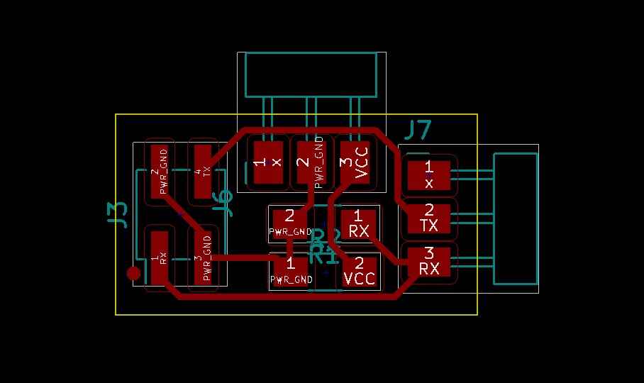
In comparison to the pain and suffering from the ESP board, this board was a dream. I drew the schematic and the PCB design in 30 minutes. I drew it in the OLED schematic so I would get the orientation right.
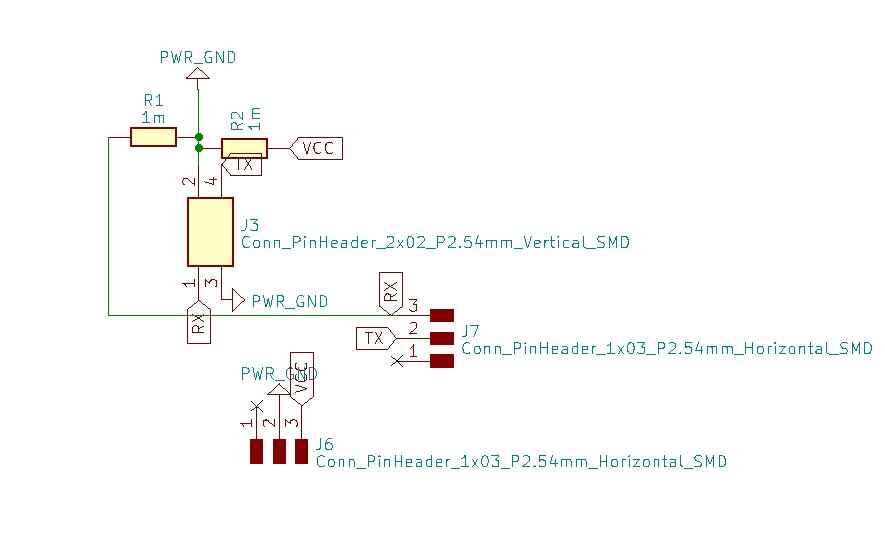
Schematic:
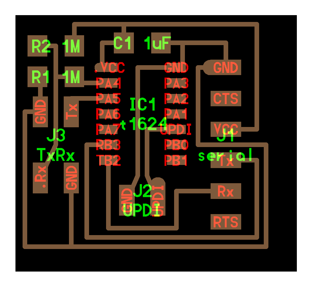
PCB design:
Milling and soldering
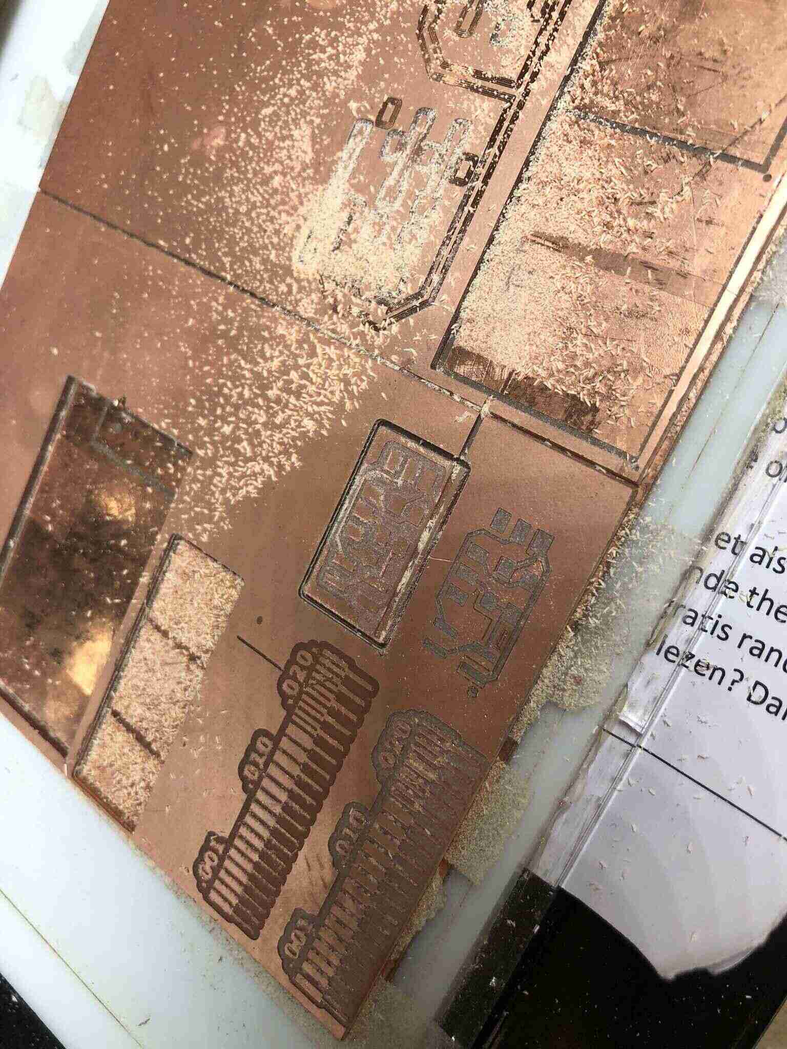
I wasn’t very awake so I forgot to invert the SVG the first time; the second time I made a mistake with the outline and it was too big, but it scraped past the traces and I could still use the board.
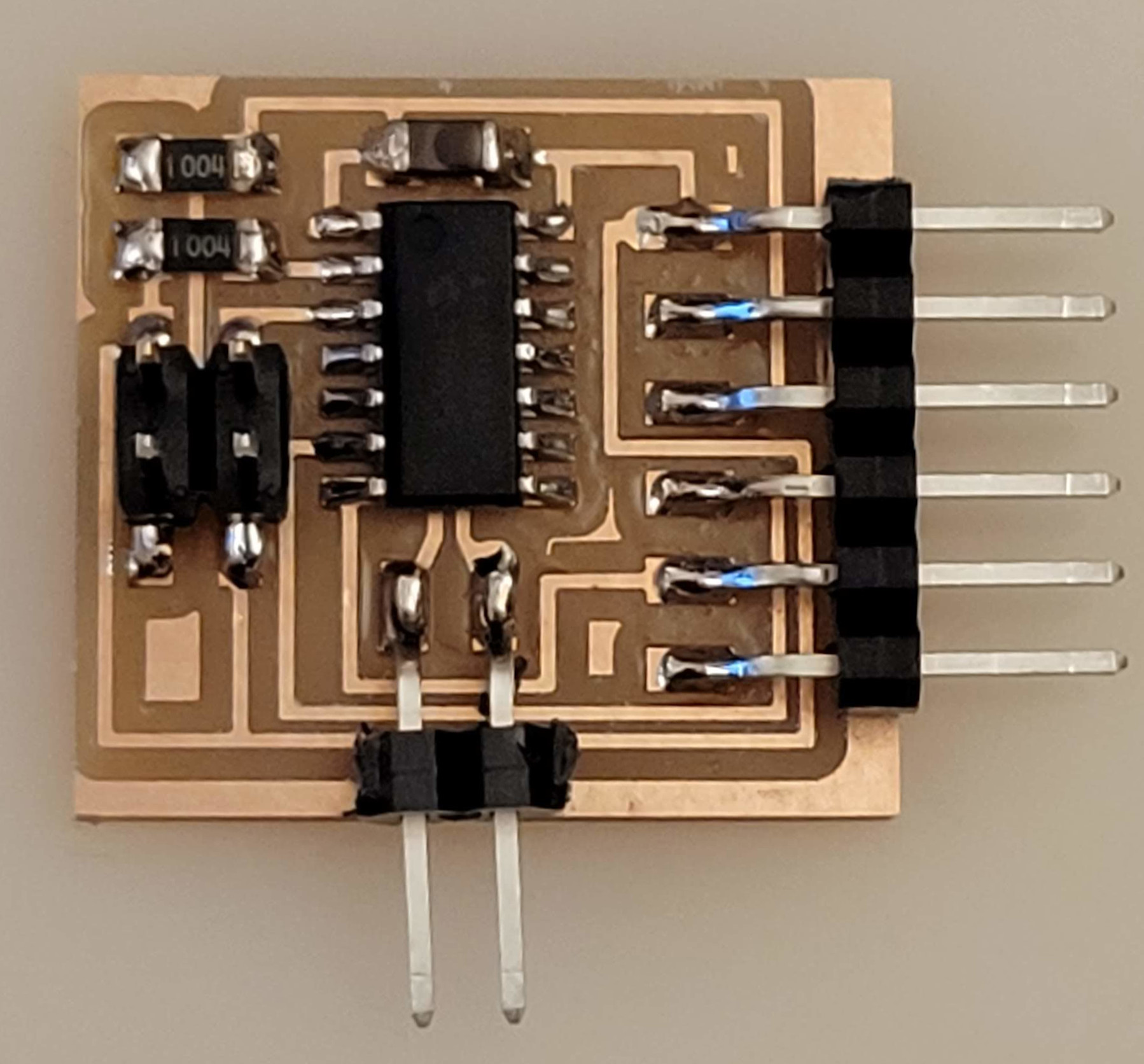
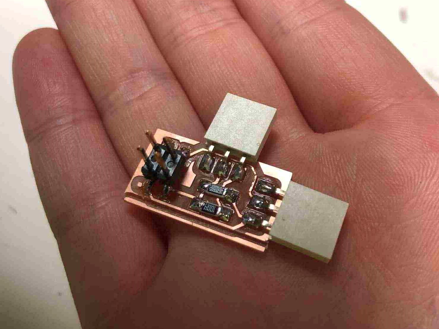
Components are two 1M Ohm resistors, two female 1x03 connectors and one male 2x02 header pins. It’s a cute tiny board after soldering:

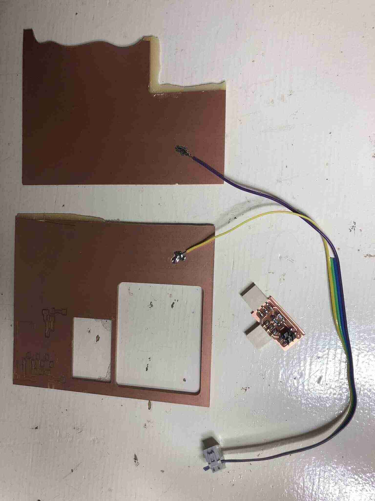
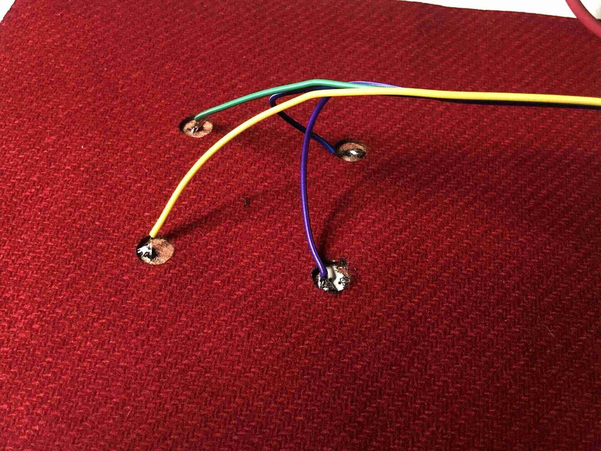
To make the electrodes, I just grabbed two leftover copper boards and soldered my receive & transmit wires to them so I could try out the concept.
Programming
This is how the board is connected to the OLED development board:
The yellow wire is connected to the receive pin, the purple wire to the transmitting pin.
I first tried to upload Neil’s provided code (with pins set correctly) but I got this error during compiling:
C:\Users\mvoss\Documents\Arduino\txrxstepresponse\txrxstepresponse.ino: In function 'void setup()':
txrxstepresponse:23:4: error: 'analogSampleDuration' was not declared in this scope
    analogSampleDuration(5); // speed up ADC sampling
    ^~~~~~~~~~~~~~~~~~~~
C:\Users\mvoss\Documents\Arduino\txrxstepresponse\txrxstepresponse.ino:23:4: note: suggested alternative: 'analogSetAttenuation'
    analogSampleDuration(5); // speed up ADC sampling
    ^~~~~~~~~~~~~~~~~~~~
    analogSetAttenuation
C:\Users\mvoss\Documents\Arduino\txrxstepresponse\txrxstepresponse.ino: In function 'void loop()':
txrxstepresponse:32:7: error: 'digitalWriteFast' was not declared in this scope
       digitalWriteFast(txpin,HIGH); // charge up
       ^~~~~~~~~~~~~~~~
C:\Users\mvoss\Documents\Arduino\txrxstepresponse\txrxstepresponse.ino:32:7: note: suggested alternative: 'digitalWrite'
       digitalWriteFast(txpin,HIGH); // charge up
       ^~~~~~~~~~~~~~~~
       digitalWrite
exit status 1
'analogSampleDuration' was not declared in this scope
I looked it up and I found this tutorial. ADC Functions in Arduino that can be used with ESP32 can be found on this website. I ended up just disabling analogSampleDuration and analogReadResolution and changing digitalWriteFast to digitalWrite and it worked fine.
I also read that ‘reading an analog value with the ESP32 means you can measure varying voltage levels between 0 V and 3.3 V.’ So I connected the power to the 3.3V output and not the 5V output. The analog input pins have 12-bit resolution. This means that when you read an analog input, its range may vary from 0 to 4095.
Code
//
// hello.txrx.t1624.ino
//
// ATtiny1624 step response
//
// Neil Gershenfeld 11/14/21
//
// This work may be reproduced, modified, distributed,
// performed, and displayed for any purpose, but must
// acknowledge this project. Copyright is retained and
// must be preserved. The work is provided as is; no
// warranty is provided, and users accept all liability.
//

#define rxpin A3 // receive pin
#define txpin A2 // transmit pin
#define settle 100 // settle time
#define samples 100 // number of samples to accumulate

void setup() {
  Serial.begin(115200); // start serial
  pinMode(txpin, OUTPUT); // set transmit pin to output
}

void loop() {
  int32_t up, down;
  up = down = 0;
  noInterrupts(); // disable interrupts while measuring
  for (int i = 0; i < samples; ++i) {
    digitalWrite(txpin, HIGH); // charge up
    up += analogRead(rxpin); // read
    delayMicroseconds(settle); //settle
    digitalWrite(txpin, LOW); // charge down
    down += analogRead(rxpin); // read
    delayMicroseconds(settle); // settle
  }
  interrupts(); // enable interrupts after measuring
  Serial.println(up - down); // send difference
  Serial.flush(); // finish communicating before measuring
}
Trying it out
Here you can see the values change when the receive and transmit electrode are touched at the same time: the value in the serial monitor goes up to 409500. I don’t know where those extra two zeros are coming from, the maximum reading should be 4095.
Capacitive sensing
I really wanted to try capacitive sensing since it’s a sensing method that has a lot of possible applications in tactile interfaces, and the interaction can be really intuitive and experimental. For my purposes they have a better interaction than step response sensing, since for this you only need to touch or approach one area as opposed to two.
First of all, what is it and how does it work?
A capacitive sensor is an electronic device that can detect solid or liquid targets without physical contact. To detect these targets, capacitive sensors emit an electrical field from the sensing end of the sensor. Any target that can disrupt this electrical field can be detected by a capacitive sensor. Some examples of the solid materials a capacitive sensor can detect are all types of metal, all types of plastic, wood, paper, glass, and cloth. (via https://realpars.com/capacitive-sensor/)
Touchlib library
I wanted to try out e-textiles capacitive touch as seen on Kobakant; this makes use of the Touchlib library that is compatible with various ATmega chips (like the Arduino UNO has) but also the ESP32.
This kind of capacitive sensing only needs one pin per sensor, there is no separate pin needed for sending data and you don’t need to touch or approach two pads at the same time. You can use this to make touchpad buttons or flat e-textiles capacitive garments.
The library works easy enough: you just need to upload the example code provided by the library, and it guides you through the steps of setting up your capacitive sensors. When done it provides you with the code for your specific sensors.
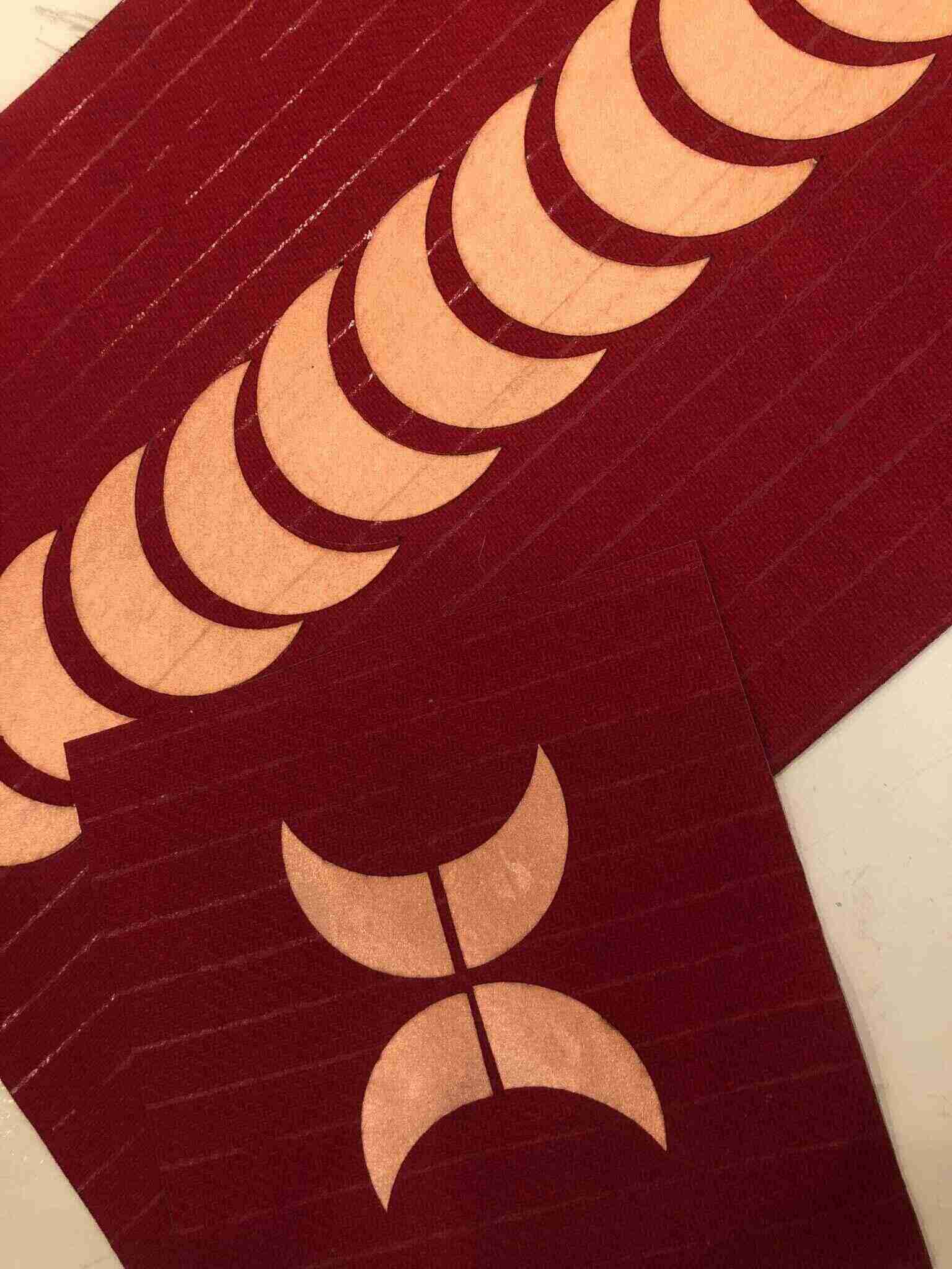
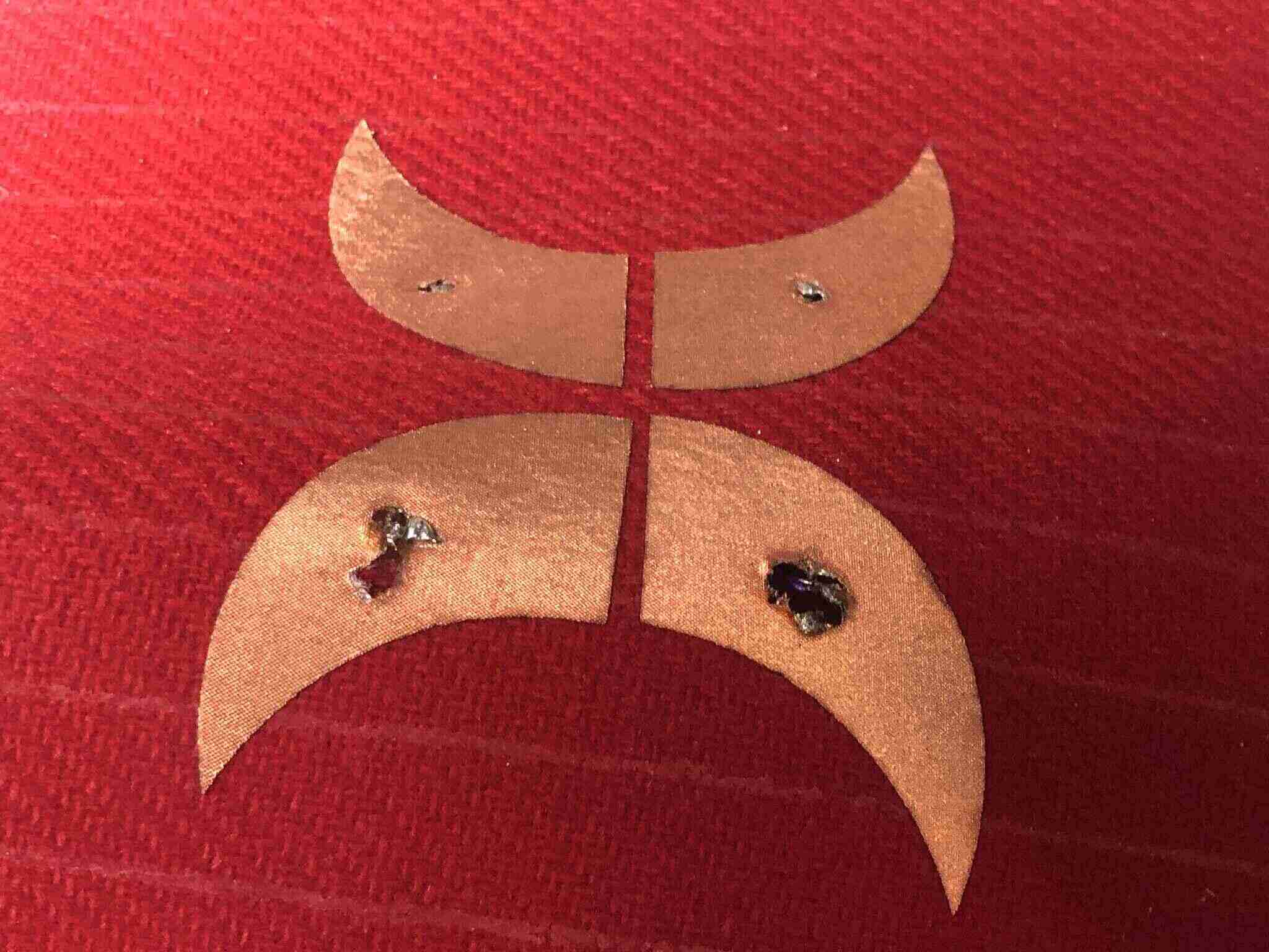
I made these samples to try it out:
Soldering did not go well, I think because I tried to solder it invisibly to the back where there was the interfacing. I didn’t get the best connection and it made big holes.
ESP32C3
I wanted to upload the example code from the Touchlib library to the XIAO ESP32C3 board, but I got this error:
soc/sens_reg.h: No such file or directory
I found it in this repository for esp-idf but just downloading the file and placing it in the libraries folder didn’t work so I downloaded the whole repository. I moved the soc folder around to find out where it was needed; in the end I put it in the src folder for the Touchlib library and then it didn’t give that error anymore but I got this:
C:\Users\mvoss\AppData\Local\Temp\arduino_modified_sketch_437528\Example00SemiAutoTuning.ino:387:24: note: suggested alternative: 'D0'
  const int pinMap[] = {T0, T1, T2, T3, T4, T5, T6, T7, T8, T9};
I replaced them as suggested but then I realized that this is the way to refer to the touch pins on the ESP32 and I wonder if it’s not working because I am trying to make it work with the XIAO and this library just isn’t compatible with the XIAO ESP.
Arduino Uno
Then I tried it with an Arduino Leonardo (I couldn’t find an Arduino Uno cable) just to see if I could get something working at least but the memory wasn’t enough:
"C:\\Program Files (x86)\\Arduino\\hardware\\tools\\avr/bin/avr-size" -A "C:\\Users\\mvoss\\AppData\\Local\\Temp\\arduino_build_121171/Example00SemiAutoTuning.ino.elf"
Sketch uses 29940 bytes (104%) of program storage space. Maximum is 28672 bytes.
Global variables use 1624 bytes (63%) of dynamic memory, leaving 936 bytes for local variables. Maximum is 2560 bytes.text section exceeds available space in board

Sketch too big; see https://support.arduino.cc/hc/en-us/articles/360013825179 for tips on reducing it.
Error compiling for board Arduino Leonardo.
Then I finally found an Arduino cable and used an Uno. In the serial monitor you have to walk through the calibration steps. It didn’t work for the last one connected to A3, probably because my connection got completely messed up with soldering.
This is the code that was generated:
#include <TouchLib.h>

/*
 * Code generated by TouchLib SemiAutoTuning.
 *
 * Hardware configuration:
 *   sensor 0: type: capacitive (CVD method), analog pin A0
 *   sensor 1: type: capacitive (CVD method), analog pin A1
 *   sensor 2: type: capacitive (CVD method), analog pin A2
 *   sensor 3: type: capacitive (CVD method), analog pin A3
 */

/*
 *  Number of sensors. For capacitive sensors: needs to be a minimum of 2. When
 * using only one sensor, set N_SENSORS to 2 and use an unused analog input pin for the second
 * sensor. For 2 or more sensors you don't need to add an unused analog input.
 */
#define N_SENSORS                       4

/*
 * Number of measurements per sensor to take in one cycle. More measurements
 * means more noise reduction / spreading, but is also slower.
 */
#define N_MEASUREMENTS_PER_SENSOR       16

/* tlSensors is the actual object that contains all the sensors */
TLSensors<N_SENSORS, N_MEASUREMENTS_PER_SENSOR> tlSensors;

void setup()
{
        Serial.begin(9600);

        #if IS_ATMEGA32U4
        while(!Serial); /* Required for ATmega32u4 processors */
        #endif

        /* Delay to make sure serial monitor receives first message */
        delay(500);
        Serial.println();
        Serial.println();
        Serial.println("Switching baudrate to 115200. Make sure to adjust baudrate in serial monitor as well!");
        Serial.println();
        Serial.println();
        Serial.end();

        /*
         * Switch baudrate to highest baudrate available. With higher baudrate,
         * CPU has more time left to do capacitive sensing and thus get better
         * signal quality.
         */
        Serial.begin(115200);
        delay(500);
        Serial.println();
        Serial.println();

        /*
         * Configuration for sensor 0:
         * Type: capacitive (CVD method)
         * Analog pin: A0
         */
        tlSensors.initialize(0, TLSampleMethodCVD);
        tlSensors.data[0].tlStructSampleMethod.CVD.pin =               A0;
        tlSensors.data[0].releasedToApproachedThreshold =              16;
        tlSensors.data[0].approachedToReleasedThreshold =              15;
        tlSensors.data[0].approachedToPressedThreshold =               2524;
        tlSensors.data[0].pressedToApproachedThreshold =               2272;
        tlSensors.data[0].calibratedMaxDelta =                         5108;
        tlSensors.data[0].filterType = TLStruct::filterTypeAverage;

        /*
         * Configuration for sensor 1:
         * Type: capacitive (CVD method)
         * Analog pin: A1
         */
        tlSensors.initialize(1, TLSampleMethodCVD);
        tlSensors.data[1].tlStructSampleMethod.CVD.pin =               A1;
        tlSensors.data[1].releasedToApproachedThreshold =              5;
        tlSensors.data[1].approachedToReleasedThreshold =              4;
        tlSensors.data[1].approachedToPressedThreshold =               10;
        tlSensors.data[1].pressedToApproachedThreshold =               9;
        tlSensors.data[1].calibratedMaxDelta =                         30;
        tlSensors.data[1].filterType = TLStruct::filterTypeAverage;

        /*
         * Configuration for sensor 2:
         * Type: capacitive (CVD method)
         * Analog pin: A2
         */
        tlSensors.initialize(2, TLSampleMethodCVD);
        tlSensors.data[2].tlStructSampleMethod.CVD.pin =               A2;
        tlSensors.data[2].releasedToApproachedThreshold =              8;
        tlSensors.data[2].approachedToReleasedThreshold =              8;
        tlSensors.data[2].approachedToPressedThreshold =               2361;
        tlSensors.data[2].pressedToApproachedThreshold =               2125;
        tlSensors.data[2].calibratedMaxDelta =                         5245;
        tlSensors.data[2].filterType = TLStruct::filterTypeAverage;

        /*
         * Configuration for sensor 3:
         * Type: capacitive (CVD method)
         * Analog pin: A3
         */
        tlSensors.initialize(3, TLSampleMethodCVD);
        tlSensors.data[3].tlStructSampleMethod.CVD.pin =               A3;
        tlSensors.data[3].releasedToApproachedThreshold =              5;
        tlSensors.data[3].approachedToReleasedThreshold =              4;
        tlSensors.data[3].approachedToPressedThreshold =               50;
        tlSensors.data[3].pressedToApproachedThreshold =               45;
        tlSensors.data[3].calibratedMaxDelta =                         55;
        tlSensors.data[3].filterType = TLStruct::filterTypeAverage;

        if (tlSensors.error) {
                Serial.println("Error detected during initialization of TouchLib. This is "
                       "probably a bug; please notify the author.");
                while (1);
        }

        Serial.println("Calibrating sensors...");
        while(tlSensors.anyButtonIsCalibrating()) {
                tlSensors.sample();
        }
        Serial.println("Calibration done...");
}

void print_sensor_state(int n)
{
        char s[32] = {'\0'};

        Serial.print(" #");
        Serial.print(n);
        Serial.print(": ");
        Serial.print(tlSensors.isCalibrating(n));
        Serial.print(" ");
        Serial.print(tlSensors.isReleased(n));
        Serial.print(" ");
        Serial.print(tlSensors.isApproached(n));
        Serial.print(" ");
        Serial.print(tlSensors.isPressed(n));
        Serial.print(" ");
        Serial.print(tlSensors.getState(n));
        Serial.print(" ");
        Serial.print(tlSensors.getStateLabel(n));
        memset(s, '\0', sizeof(s));
        memset(s, ' ', 22 - strlen(tlSensors.getStateLabel(n)));
        Serial.print(s);
}

#define BAR_LENGTH                     58 /* <-- Change this to print longer or shorter visualizations */

void loop(void)
{
        int k;

        int n = 0; /* <-- Change this number to view a different sensor */

        tlSensors.sample(); /* <-- Take a series of new samples for all sensors */

        tlSensors.printBar(n, BAR_LENGTH); /* <-- Print the visualization */

        print_sensor_state(n); /* <-- Print summary of sensor n */

        /* For capacitive + resistive sensors: k is the sensor that sensor n is paired with */
        k = tlSensors.findSensorPair(n, (n + 1) % N_SENSORS);
        if (k > -1) {
                print_sensor_state(k); /* <-- Print summary of sensor k */
        }
        Serial.println("");
}
In the video you can see 3 of them responding to touch. I think they should be calibrated again. I also noticed that when I had the sample on the table, the range of values was bigger than when I held the sample above my keyboard for filming.
TouchRead
Then I tried to use this example code using touchRead which comes with esp32 arduino boards (File > Examples > ESP32 > Touch), but I kept getting a 'touchRead' was not declared in this scope error. Then I wanted to try with the ESP32-C3-mini dev board but that one also doesn’t seem to have touch pins, so that’s unfortunate.
I also tried to update the esp32 Arduino library to 2.0.7 (I was on 2.0.6) but that didn’t do anything either. I then tried to compile it for ESP32C3 dev module but I got the same error. I guess they’re not compatible.
ESP WROOM32 After finishing the development board with the ESP WROOM, I can finally use touchRead. With the code below you can see a clear drop in value when the jumper wire is touched. I have 5 pins broken out that can use touchRead. Connecting them to every other pad on my textile touchpad works well:
Code
// ESP32 Touch Test

void setup() {
  Serial.begin(115200);
  delay(2000); // time to bring up serial monitor
}

void loop() {
  Serial.print(touchRead(T7));
  Serial.print("\t");
  Serial.print(touchRead(T6));
  Serial.print("\t");
  Serial.print(touchRead(T5));
  Serial.print("\t");
  Serial.print(touchRead(T2));
  Serial.print("\t");
  Serial.println(touchRead(T3));

  delay(200);
}
CapacitiveSensor library
I also tried the Capacitive Sensor library which works pretty easily with the Arduino. The first row doesn’t seem to work though, even after changing pin. I also tried it with the ESP but it wouldn’t compile (more on that here).
A downside to this library seems to be that once it detects touch, the reading runs way slower.
One day later I realized the first row is not capacitive sensing data but the check on performance in ms; and I should’ve changed Serial.println(total3); to Serial.print(total3);. I somehow failed to notice that the values for the fourth sensor output were in the second column. So actually the code is working fine with this sample. The only thing that I’m missing is a couple more analog pins so I can use all ten pads.
Teensy
I tried touchRead on the Teensy 4.0 I had because I read that Teensy has touch pins too. Sadly only the earlier versions have it, and Teensy 4.0 doesn’t. I also tried it with a piece of fabric on top of the copper fabric which it detected just fine too.
The higher the resistance value (5M-50M), the bigger the sensitivity of these capacitive sensors (but the lower the accuracy). With a lower value (500k-5M approximately) it functions more like a button and only detects touch.
Code
#include <CapacitiveSensor.h>

/*
 * CapitiveSense Library Demo Sketch
 * Paul Badger 2008
 * Uses a high value resistor e.g. 10M between send pin and receive pin
 * Resistor effects sensitivity, experiment with values, 50K - 50M. Larger resistor values yield larger sensor values.
 * Receive pin is the sensor pin - try different amounts of foil/metal on this pin
 */


CapacitiveSensor   cs_17_6 = CapacitiveSensor(17,6);        // 10M resistor between pins 4 & 2, pin 6 is sensor pin, add a wire and or foil if desired
CapacitiveSensor   cs_17_7 = CapacitiveSensor(17,7);        // 10M resistor between pins 4 & 6, pin 7 is sensor pin, add a wire and or foil
CapacitiveSensor   cs_17_8 = CapacitiveSensor(17,8);        // 10M resistor between pins 4 & 8, pin 8 is sensor pin, add a wire and or foil
CapacitiveSensor   cs_17_9 = CapacitiveSensor(17,9);        // 10M resistor between pins 4 & 8, pin 9 is sensor pin, add a wire and or foil

void setup()
{
   Serial.begin(9600);
}

void loop()
{
    long start = millis();
    long total1 =  cs_17_6.capacitiveSensor(30);
    long total2 =  cs_17_7.capacitiveSensor(30);
    long total3 =  cs_17_8.capacitiveSensor(30);
    long total4 =  cs_17_9.capacitiveSensor(30);

    Serial.print(millis() - start);        // check on performance in milliseconds
    Serial.print("\t");                    // tab character for debug windown spacing

    Serial.print(total1);                  // print sensor output 1
    Serial.print("\t");
    Serial.print(total2);                  // print sensor output 2
    Serial.print("\t");
    Serial.print(total3);                // print sensor output 3
    Serial.print("\t");
    Serial.println(total4);                // print sensor output 4
    delay(10);                             // arbitrary delay to limit data to serial port
}
ADC Touch library
- ADC Touch library is not compatible with ESP32 nor RP2040; it’s only compatible with avr architecture chips.
- https://microcontrollerslab.com/esp32-touch-sensor-button-example/
No library
- https://forum.arduino.cc/t/capacitive-sensing-without-library/484848: uploads fine but doesn’t do anything.
- https://github.com/TheRoam/TRW_AnalogTouch doesn’t change values when touched.
Phototransistor
I then went back to the board I made during electronics production that had a phototransistor that didn’t work. This time I didn’t get a constant reading of 4095 but the measurements weren’t correct either. With Adrian’s Processing code you can see that the phototransistor responds to being covered by a finger, but the values are incorrect.
The next day I realized that I didn’t solder the 10k Ohm resistor attached to the 3.3V power pin back (it’s an emergency jumper wire that got loose) on the board. I put it back, and I got better readings than a couple of weeks ago, but still not correct. When pointed at the ceiling, I got a measurement of about -1750 and when approached with my hand it was getting closer to -3300. When turning off the mapping line in Adrian’s code (sensorValue = map(sensorValue, 0, 1024, 1024, 0);) I got results from about 2700 when pointed at the ceiling to 4095 when fully covered. I don’t understand why Adrian is mapping the values from 0 to 1024 because the range of readings is 0 to 4095.
What I noticed is that the value needs to be calibrated and mapped to centimeters because the readings are not in centimeters; it’s a function of light in comparison to current (check with oscilloscope). Also the range seems to be 0-60cm, after that there is no change in reading.
Thoughts on the XIAO boards
I honestly find the XIAO boards pretty useless. They are blocking me in actually learning how to work different architectures and programmers. I feel like I’m still shit with electronics and I feel like the XIAO boards are really holding me back because they don’t have many pins to work with and they don’t have as many peripherals available as the chips are actually capable of.
Now the problem that I run into is that I only know how to work with the FabTinyISP to program boards, and I couldn’t find a good documentation to figure it out so I have to check with Henk how to continue. I just kind of want to abandon the XIAO boards altogether and work with all kinds of different chips depending on what works best for what I want to achieve.
Group assignment
The group assignment this week is to probe the digital and analog signals from an input device. We’re probing a potentiometer and a rotary encoder. We’re using the lab oscilloscope and a logic analyzer to visualize the signals (both connected to ground and the pin you want to read).
Slide potentiometer
We first probed the analog signals of a slide potentiometer, and mapped the 0-1023 values from 0 to 5V in the Arduino serial monitor. You can see the results in the video.
Code
We used the code and schematic from here. This is the code used:
/*
 * Created by ArduinoGetStarted.com
 *
 * This example code is in the public domain
 *
 * Tutorial page: https://arduinogetstarted.com/tutorials/arduino-potentiometer
 */

float floatMap(float x, float in_min, float in_max, float out_min, float out_max) {
  return (x - in_min) * (out_max - out_min) / (in_max - in_min) + out_min;
}

// the setup routine runs once when you press reset:
void setup() {
  // initialize serial communication at 9600 bits per second:
  Serial.begin(9600);
}

// the loop routine runs over and over again forever:
void loop() {
  // read the input on analog pin A0:
  int analogValue = analogRead(A0);
  // Rescale to potentiometer's voltage (from 0V to 5V):
  float voltage = floatMap(analogValue, 0, 1023, 0, 5);

  // print out the value you read:
  Serial.print("Analog: ");
  Serial.print(analogValue);
  Serial.print(", Voltage: ");
  Serial.println(voltage);
  delay(1000);
}
Rotary encoder
I installed Logic 2 a couple of weeks ago but I hadn’t used it before. This is what the interface looks like with 3 channels selected.
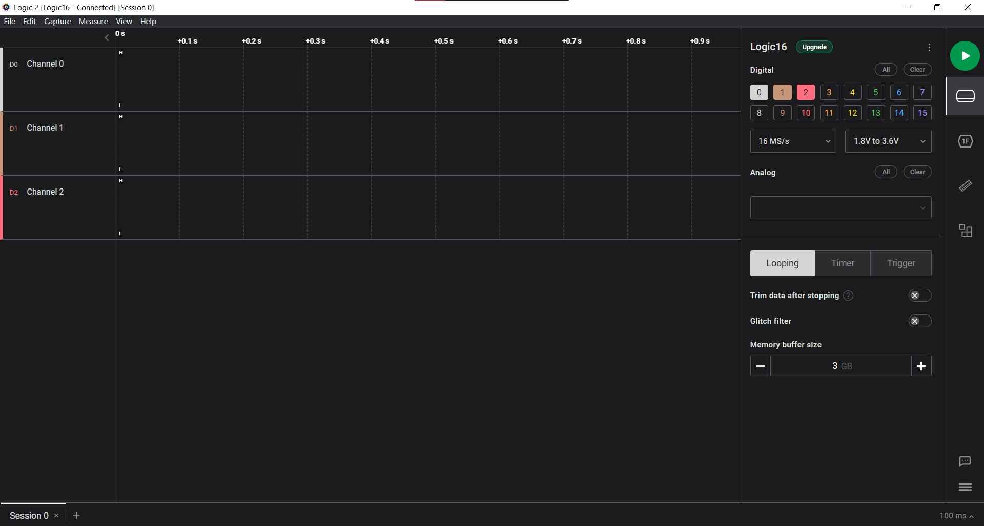
In Logic 2, channel 0 is connected to the data line, channel 1 to the clock. You measure whether clock signal is leading or trailing to determine the direction of rotation.
What’s going on in the code is:
- When not rotating the knob, the clock on channel 1 is high.
- If the digitalRead of the clock pin is 0 and the data signal hasn’t been processed yet, delay for 5ms and set processed value to 1.
- If the reading of the data pin is 1 (high), it’s being rotated in the counterclockwise direction.
- Clock signal is trailing
- If the reading of the data pin is 0 (low), it’s being rotated in the clockwise direction. When the digitalRead of the clock pin is 1 again, the processed value is set to 0 again.
- Clock signal is leading (double check)
Erwin and Pieter were figuring out why there was no response from the switch in Logic. Samson and I had a look at it and simplified the wiring. At first the switch was floating for us in the serial monitor, but after activating the internal pullup resistor, we got accurate readings (1 when unpressed, 0 when pressed).
We used a rotary encoder switch with breakout board like the image on the right. When wiring it like the image and with the code below added it worked fine; the readings in logic corresponded to what we saw in the serial monitor.


Channel 2 is connected to the switch.
Code
This is what I added to the code Henk provided:
pinMode(PIN_SWITCH, INPUT_PULLUP); // Added to setup

Serial.println(digitalRead(PIN_SWITCH)); // Added to loop
  delay(100);
Code used for the rotary encoder:
#define PIN_CLOCK   2
#define PIN_DATA    3
#define PIN_SWITCH  4

uint8_t processed = 0;
uint8_t count = 127;

void setup() {
  pinMode(PIN_CLOCK, INPUT);
  pinMode(PIN_DATA, INPUT);
  pinMode(PIN_SWITCH, INPUT_PULLUP);
  Serial.begin(115200);
}

void loop() {
  if (digitalRead(PIN_CLOCK) == 0 && processed == 0) {
    delay(5);
    processed = 1;
    if (digitalRead(PIN_DATA) == 1) {
      Serial.println("counterclockwise");
      count--;
    } else {
      Serial.println("clockwise");
      count++;
    }
    Serial.println(count);
  }
  if (digitalRead(PIN_CLOCK) == 1) {
    delay(5);
    processed = 0;
  }
  Serial.println(digitalRead(PIN_SWITCH));
  delay(100);
}
Links
Files
Lecture notes
Capacitor: hardware debouncing over VCC and data
AVR128DB..
- TWI: two wire interface
- Buttons: debouncing, pullup resistor, give some time between readings
I2C is a very simple protocol, can do it on any pin and any processor (SCL & SDA)
-
Magnetic field: Hall effect
-
Potentiometer
-
Step response:
- all kinds of sensors that work with resistance, capacitance, inductance, position, pressure, tilt, acceleration, humidity, proximity, touch, multitouch, force, bending, ..
- 2 electrodes (just two pads with copper), dielectric field
- Load cell: can measure force
- Velostat
Light sensor obsolete, phototransistor is better
IR: your body makes IR light, IR sensor can detect it. Radar: microwave signal and mixes a signal that reflects back. If nothing is moving there is no change. If something is moving there is a doppler shift so there is a change in frequency; it detects motion
Time of light sensor is superior to sonar sensors like the ultrasonic sensor
Microphone MEMS: digital microphone makes your life so much easier I2S: language of speakers and microphones in neil’s example you can do I2S in software because it’s so fast when you make a loop in software it can vary in time unrolled loop 32 bit signal audio so the timing is predictable and faster it’s more typical to use an i2s library with an ic that can do it
Piezo: sensing vibrations Force sensing sensors Strain gauge Load cell -> You can do all that with step response and electrodes
Erwin’s lecture
Analog and digital inputs Analog: continuously changing unit, converted to a resistance, capacitance or current (then to voltage) Digital: in steps Measuring by sampling values over time and then extrapolating how the signal looks visually You can amplify signals before sampling Golden rule is sampling twice the frequency, the more samples the more accurate (but costs more memory)
Digital: physical unit is converted into opening or closing a circuit; when you sample it you get a zero or a 1 (PWM changes duty cycle)
ADC
ADC: measures voltage on a pin over time, more bits is more resolution (8 bit is 255 steps, 10 bit is 1023 steps, 12 bits) every step is 5V/255 or 5V/1023
This is what an ADC looks like:

Arduino Uno: A0-A5 pins are ADC pins
Sometimes in cheaper microcontrollers you can connect the ADC to a certain pin and switch between pins with that same ADC because an ADC is relatively expensive
1V1 reference voltage is always 1.1V so you can use it as a reference to measure voltage regardless of whether VCC is 5V or 3.3V
Wheatstone brudge: usually not in a microcontroller (but sometimes in sensors like load cells); one resistor is variable and you can use it to measure way smaller voltage changes, much more accuracy also with a low res ADC
Analogread and delay: to determine sample rate
GPIO: is input lower or higher than a certain voltage value, for example 0-0.33 VCC LOW, 0.66-1 VCC is high - there is an undefined voltage area that can cause interesting problems - pull-up or pull-down hardware with comparator, or in software
Protocol
Typically two-way communication
- Address + command to sensor; address + value from sensor
- Host/client/multi-client
1wire, TWI (two wires) (invented by Dallas; called 1wire because only one wire for data)
- VCC/DATA/GND
- VCC+DATA/GND (combining by small variations in voltage) 12C (invented by Phillips)
- Communication on a board between components
- 7 bit address for IC, most of them fixed, so if you send a command to that address all components with that address react
- You give up two pins (SDA, SCL) but you can get 8/16/32 pins back with a PCA9555 I/O expander SPI (invented by Motorola)
- Exchange of bits between host - client (MISO - MOSI); one chip at a time
- Use chip select (CS) to specify which client to talk to
- Very fast but needs more pins
- Used for flash memory/sd cards, tft screens, real time clock DS1302 Serial
- Rx/Tx with a baudrate
- Generic UART asynchronous (no clock pin) universal asynchronous receive transmit
- For example: ultrasonic, GPS, CO2 PWM
- Duty cycle
- Can use to send data with the clock signal
- For use in EMC-noisy environments Hardware or bit-banging: describing in software what the behavior of the pin should
Physical things to measure
SI system:
- Seconds (s) in time
- Meter (m) for length
- Kilogram (kg) for mass
- Ampere (A) for electric current
- Kelvin (K) for thermodynamic temp
- Mole (mol) for amount of substance
- Candela (cd) for luminous intensity
These are the only fundamental units you need, everything else is derived (including voltage)