Computer-Aided Design
This week is all about designing in 2D and 3D! My goal this week is to learn some Rhino, and add some Grasshopper and improve on it next week when we have to design something parametrically and lasercut it. What I know about Rhino is that Rhino itself is not necessarily great for parametric modeling, but Grasshopper definitely is, so it should be possible to make something parametric then (and if it really doesn’t work out, I can still use Fusion360 which I’m more familiar with). I’m also still finetuning my final project idea, because my idea (a sound suit) is probably too ambitious in its current shape. If I’m going to model a wearable final project, I’m also going to use CLO3D to make it, but I still want to work with Rhino this week, so I might try to sculpt a mannequin to work on in CLO3D (although Blender might be more useful for it).
OpenSCAD
Bas (student from last year) showed us the basics of OpenSCAD on Thursday. OpenSCAD is open source modeling software in which you model with a script in the editor on the left, and look at what you’ve made by previewing and rendering on the right. It’s useful for CAD designing and collaborating, but less useful for artistic purposes. You can either model using a CSG workflow (constructive solid geometry, starting with 3D shapes) or you can extrude 2D outlines.
“OpenSCAD is not an interactive modeller. Instead it is something like a 3D-compiler that reads in a script file that describes the object and renders the 3D model from this script file. This gives you (the designer) full control over the modelling process and enables you to easily change any step in the modelling process or make designs that are defined by configurable parameters.” (via https://openscad.org/about.html)
A coworker of Pieter came by the lab today and showed us this big open source project on an open source microscope completely modeled in OpenSCAD. The great thing about collaborating in a project made in OpenSCAD is that it’s really easy to share files because the file is basically just text which is very lightweight, and you can configure a git workflow that renders the 3D files for each commit right in the repository. What they did in this case was embed the commit number right into the generated STL files so you can keep track of what part belongs to what iteration.
Trying it out
When you start out by drawing a circle (in this case radius 1, there is no specific unit number in OpenSCAD) and you preview or render it, you’ll notice it doesn’t look anything like a circle. This is because the base resolution is pretty low by default. With a declaration of $fn = 50, you can increase the facet number used for previewing and rendering so it looks more like a circle.

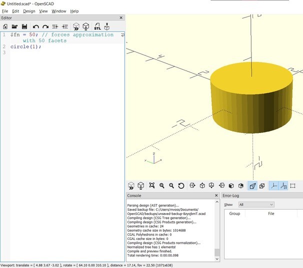
When you click preview, you get a fast view of your script. It doesn’t do 2D shapes so that’s why it’s in 3D here. If you actually render it, you get the correct view.

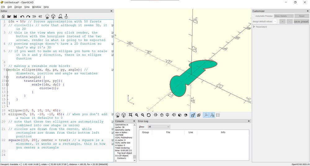
There’s no ellipse function in OpenScad so if you want an ellipse, you have to scale the x and y axes of the circle with a scale function.

It’s pretty annoying to have to constantly repeat the scale operation if you wanna create multiple ellipses. What you can do to solve this is to create a module, which is a reusable code block.

The variables used in the module then have to be given a value when calling the module.

To be extra confusing, when you want to draw a rectangle, you can use the square function; you don’t have to do something as cumbersome as when you want an ellipse.
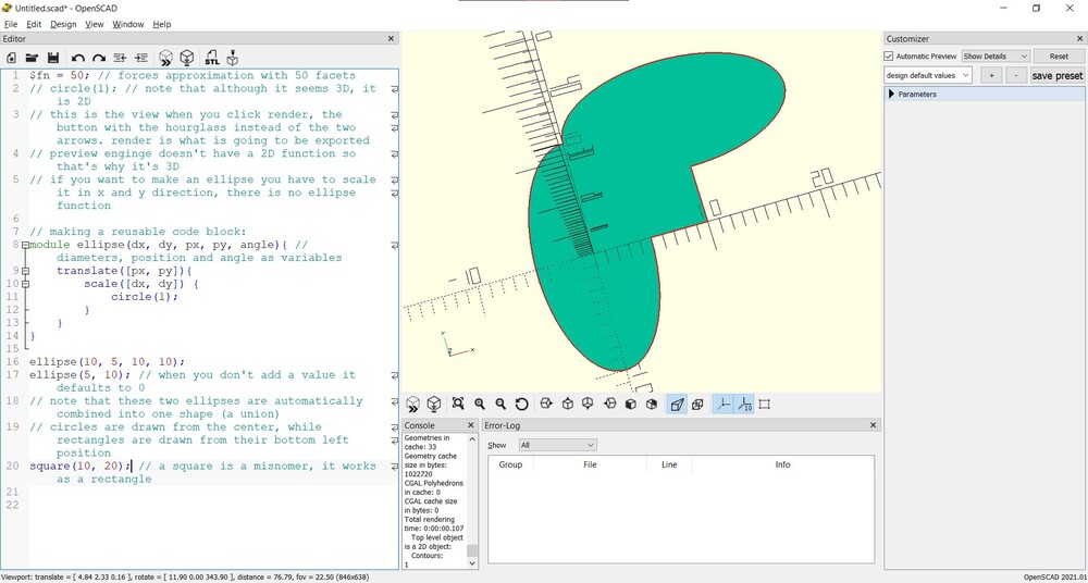
The default position of a circle is centered in (0,0,0), while the default position of a rectangle is with it’s left bottom corner on (0,0,0). To center a rectangle, use center = true.
You can also use boolean operations such as BooleanDifference, which substracts the second shape from the first shape. BooleanIntersection leaves only where the two shapes are overlapping, BooleanUnion combines the shapes and BooleanSplit cuts the shapes where they intersect without deleting anything.

It’s not possible to combine 2D shapes with 3D shapes.

If you place a # in front of a function that would normally be invisible, you can see it as a translucent red shape. This was very useful because I was very confused as to why my shape seemed to be cut out by two shapes instead of the one that I provided.

Code
Here is the code that I wrote during this tutorial (including notes):
$fn = 50; // forces approximation with 50 facets
// circle(1); // note that although it seems 3D, it is 2D
// this is the view when you click render, the button with the hourglass instead of the two arrows. render is what is going to be exported
// preview enginge doesn't have a 2D function so that's why it's 3D
// if you want to make an ellipse you have to scale it in x and y direction, there is no ellipse function

// making a reusable code block:
module ellipse(dx, dy, px, py, angle){ // diameters, position and angle as variables
    rotate(angle) {
        translate([px, py]){
            scale([dx, dy]) {
                circle(1);
            }
        }
    }
}

ellipse(10, 5, 10, 10, 45);
ellipse(5, 10, -10, -10, 45); // when you don't add a value it defaults to 0
// note that these two ellipses are automatically combined into one shape (a union)
// circles are drawn from the center, while rectangles are drawn from their bottom left position
square([10, 20], center = true); // a square is a misnomer, it works as a rectangle. this is how you center a rectangle
$fn = 50;

// making a reusable code block:
module sphere1(dx, dy, px, py, angle){ // diameters, position and angle as variables

    rotate(angle) {
        translate([px, py]){
            scale([dx, dy]) {
                sphere(1);
            }
        }
    }
}

difference(){
    sphere1(70, 20, 10, 10, 45);
    #sphere1(50, 10, 5, 0, 0); // if you place a hashtag in front of the command, you can see the negative of it
}
Notes
- A module is a reusable code block
- You can use scripts (python or shell script) to make many random models (with a random seed) (useful for example when you need a lot of snowflakes) that are similar but not the same.
- Cheat sheet
- OpenSCAD tutorial by Bas Pijls
Opinion
I like the idea of modeling with code, but I don’t like how a model in OpenSCAD looks. As they said themselves this program is not really for you if you want to make things that look nice, and I do miss the ability to click on things and work in a way that is more intuitive to me. For simple shapes I would use it again theoretically, but in practice I would probably use any other program that can do simple shapes too.
Rhino
My goal for this week is to learn how to use Rhino. I’ve worked through a couple of Grasshopper tutorials in the past, but I’ve never really used Rhino after that, and since it’s used extensively within the Fabricademy I get quite a few questions about it from the students working with it. Our current intern Aslı is an expert in Rhino and Grasshopper and she’s making amazing things with it with what seems to be a lot of ease (and probably a lot of experience) so it seems like a very versatile software to me. I want to train myself to make as much use of the command bar as possible, because I think it will make me much faster at using Rhino.
Aslı gave us a quick demo of Rhino, but since it was the weekly open day of the fablab and we had a visitor, I missed out on a large chunk of it. I decided to start out by watching some tutorials and then asking her for advice on good practice after I have a basic understanding of where I can find what. I started out with the tutorials on the Rhino website. Since I’m on a Windows computer, I started with the Windows - Interface Basics video.
Interface
There are 4 viewports that you start out with when you open a new project.
Navigation in the perspective viewport (top right):
- Rotation: right mouse button click and drag
- Pan: shift + right mouse button click and drag
- One of the first things I did was figuring out how to pan by clicking the middle mouse button (scroll wheel) and dragging; so now that’s also possible (this is my prefered method of panning in other software too). To change it go to
File > Properties... > Mouse
- One of the first things I did was figuring out how to pan by clicking the middle mouse button (scroll wheel) and dragging; so now that’s also possible (this is my prefered method of panning in other software too). To change it go to
- Zoom: scrolling up and down with the scroll wheel

Navigation in the three orthogonal viewports:
- No rotation possible here (for obvious reasons)
- Pan: right mouse button click and drag (and also scroll wheel click and drag now)
- Zoom: scrolling up and down with the scroll wheel
Double click the name of the viewport to expand to that viewport, and double click again to move back to the four window view. Ctrl + tab while in a maximized view to switch between views. View the settings menu per viewport by right clicking the name of the viewport.
There are three ways to access functions in Rhino:
- Clicking on icons in a toolbar group. The sidebar is context dependent and changes per toolbar group
- Using the dropdown menus in the top bar
- Typing the command name in the command bar. It has an autocomplete and a ‘fuzzy’ autocomplete for suggestions
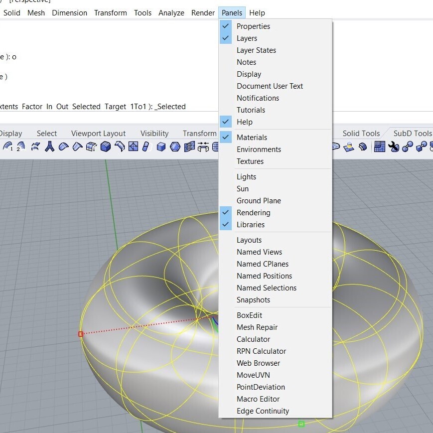
To add toolbars, rightclick the toolbar > show toolbar to see the list. On the right side of the viewports there are panels with properties, display settings, layers, rendering etc. You can rearrange them if you want and you can add even more or hide some of them (see the full list below).

The series of checkboxes at the bottom of the screen are Osnaps (object snaps), which enable and disable the ability to snap to certain objects. Below that there’s Grid Snap, which snaps to the lines in the viewports. You can see the units in the Document Properties under Grid and Units.

- If you wanna move an object around in only X or Y direction, hold shift while dragging; if you wanna move only in the Z direction hold ctrl while dragging.
- To enable or disable the Gumball (to move, rotate or scale in X, Y or Z direction) type Gumball, then O for on or F for off.

Object types
Different geometry types:
- Points: have no volume, don’t represent volume, just X, Y, Z values
- Curves: created by connecting points in space. There are three types:
- Lines (between two points)
- Conics (arcs, ellips, circles)
- Freeform curves
- Surfaces: infinitely thin piece of geometry that can be closed (representing a volume) or open (like a sheet of paper). They’re controlled with control points just like curves. Control point editing is a common workflow for finding forms in Rhino.
- Polysurface: compounds of single surfaces joined together. You can’t edit them with control points, instead you can edit them with Solid Tools
- SubD objects: subdivision objects, works like clay, sculptural modeling. They consist of faces, edges and vertices. You can sculpt them by pulling and pushing on these faces, edges and surfaces.
- Meshes: generated, not created; generated from surfaces or SubD’s. They consist of flat polygons, and the higher the number of polygons the better the approximation is to the object (unless you’re modelling a really simple cube), but also the heavier the file will be (and if you have an older computer like me, it probably won’t like it too much). Making meshes is usually the the last step before you export it to something like an STL.
Trying it out
To draw this random curve, I typed ‘Curve’ and clicked in a couple of random places, and pressed enter.

If you want to change the curve, you can select the curve by clicking it with the left mouse button and moving the white circles around that control the shape of the curve (these are called the control points).

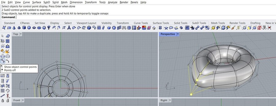
I tried making a torus and warping it like in the reference video, but every time I tried to drag something I would just move the entire torus. With the ‘show object control points’ selected (see below) it worked, so I thought when I typed in Torus in the command bar, I didn’t make a SubD object but something else. However when I scrolled back in the command bar (nice to have a history of what you’ve done) it said SubD torus there, so I was a little confused; I’ll look into it later.
“Traditionally SubD objects are mesh-based and lend themselves well to more approximate types of modeling such as character modeling and creating smooth organic forms. Rhino SubD objects are, however, high precision spline-based surfaces and thus introduce a level of accuracy to the process of creating complex freeform shapes.” (via https://wiki.mcneel.com/rhino/7/tutorial/videos/subd)
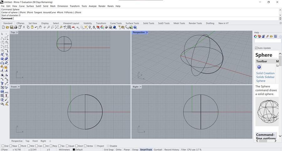
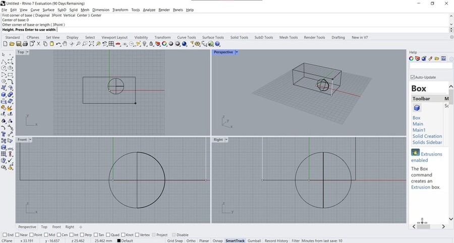
Making a sphere and then a box:
Command: Sphere
Center of sphere ( 2Point  3Point  Tangent  AroundCurve  4Point  FitPoints ): 2Point
Start of diameter: 0
End of diameter: 20
Command: _Box
First corner of base ( Diagonal  3Point  Vertical  Center ): Center
Center of base: 0
Other corner of base or length ( 3Point )
Height. Press Enter to use width
Notes
Some things I learned from this video:
- Rhino started out as a plugin for AutoCAD
- The Command line separates it from parametric programs such as Fusion, Solidworks, Onshape
- It’s a NURBS (Non-uniform rational B-spline) modeler as opposed to a polygon/mesh based modeler (like Blender).
NURBS are mathematical representations of 3D geometry that can accurately describe any shape from a simple 2D line, circle, arc, or curve to the most complex 3D organic free-form surface or solid. Because of their flexibility and accuracy, NURBS models can be used in any process, from illustration and animation to manufacturing. (via https://www.rhino3d.com/features/nurbs/)
- Rhino is a surface editor. If you model a box, what Rhino is actually doing is creating 6 planes and connecting them like a box. With the explode command you can separate the box into 6 surfaces (and you can then use control points to warp the individual control points on the separate surfaces)
- To check whether a shape is closed, you can use the Volume command, and if it gives you a number, you know it’s a closed surface. If the surface is not closed you’ll get an error message stating so.
- To analyse the surfaces and to find open edges, use ShowEdges: magenta lines are ‘naked edges’. You can close open edges with JoinEdge (but it won’t be perfect as it will need a tolerance)
- Use the Cap command to quickly close edges
- Again, you’re not working with solids, you’re working with surfaces
- Join and Explode are basically opposite commands
- Spacebar to repeat the previous command
- Learn the commands!!!
- Osnap is super useful because you can draw relative to what you’ve already drawn
- Use shortcuts (aliases) to become really fast
- Escape to deselect object
- Zs: zoom to selected
Modeling a final project
I want to make bases for masks in Rhino, because for my final project I want to make a wearable object. I want to try SubD surfaces, which is new in Rhino 7.
Steps to explore masks in 3D
- Model a head with SubD in Rhino > export to Blender for height mapping
- Make it with Grasshopper to modify shape
- Model a RGB LED or a Neopixel > export to CLO3D as a button to make a mask
- Render in CLO3D
SubD
When you open a new file by pressing ctrl + N, you can choose a template to start with. I went for Small objects - Centimeters.
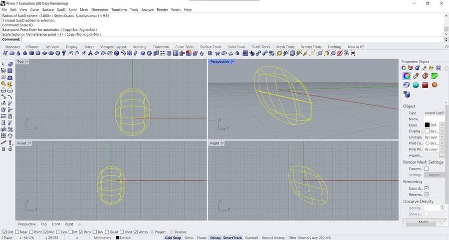
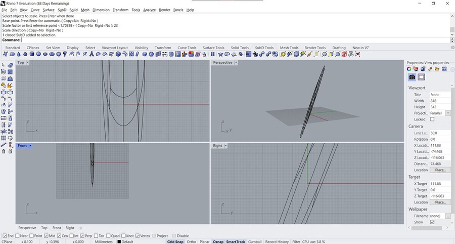
I took some rough measurements around my head and use those numbers to get to a basic shape of the head. I calculated the radius of the head with an online circumference to radius calculator which was 9.55cm for a circumference of 60cm. Then I typed in scale, and selected the Scale2D command because I wanted to scale it in the vertical direction to make it higher. From the chin to the top of the head I measured about 32cm, but that was including a curve so I measured again but this time just a straight line from the bottom of my jaw to the top of my head which was approximately 23cm. I clicked the middle of the model which was easy because I used grid & mid Osnaps, and then typed 23 to scale it to 23cm. Then I realized by looking at the perspective view that it was warped:
So I deleted the SubD object and started over but this time using Scale1D. But that also didn’t work. I checked what Scale1D and Scale2D do in the cheat sheet:
- Select objects.
- Pick an origin.
- Type the scale factor, or pick two reference points
So the second time I accidentally used 23 as a scale factor instead of using it as a reference point. To scale to an exact number you have to click two reference points (beginning and end) and then type in how big you want it to be; if you only click once and then type a number you scale it by that factor.
At this point I looked for another tutorial because I didn’t really know what I was doing at this point and I was confused by the dimensions of my model. SubD objects are spline based (just like NURBS objects) which means that they provide a continuous description of curved geometry. This means that it is an exact workflow, in contrast to mesh based objects which are approximate workflows. SubD objects can be translated losslessly into NURBS objects.
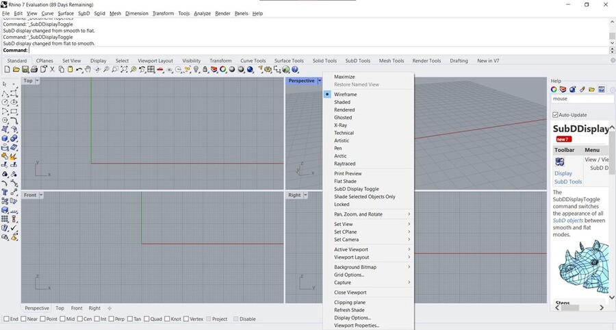
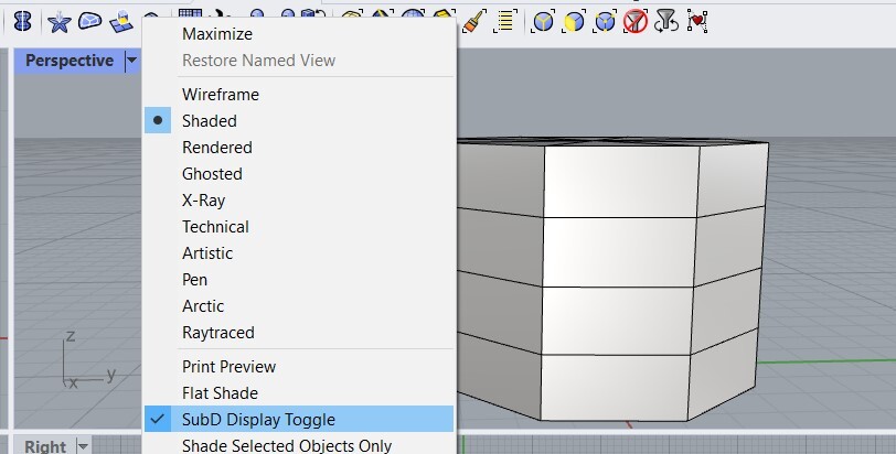
I was wondering why my SubD didn’t look nice and rounded so I started looking around and found this toggle when I clicked on the dropdown for the viewport; that did the trick.
I then clicked around until I found the EditPtOn option after which I could manipulate the SubD by pulling the points, but not by the lines or surfaces, so it’s not what I’ve seen in demos. So I continued the tutorial and shift + ctrl + left click came up which was the one I was looking for.
Some more notes on SubD:
- Double click to select an edge boundary. You can also add creases (sharp edges) with the Crease command (remove with RemoveCrease).
- Use Subdivide to add more detail (dividing surfaces into more surfaces) to specific areas or the entire model.
-
Fusion360 also has functionality similar to SubD, but way more frustrating.

-
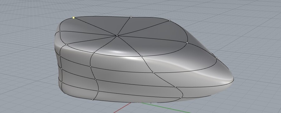
When you start a SubD the maximum number you can give it is 8 and my computer doesn’t like it but here’s what that looks like:

- Enabling the Gumball makes it easier to have control over where you’re going.
-
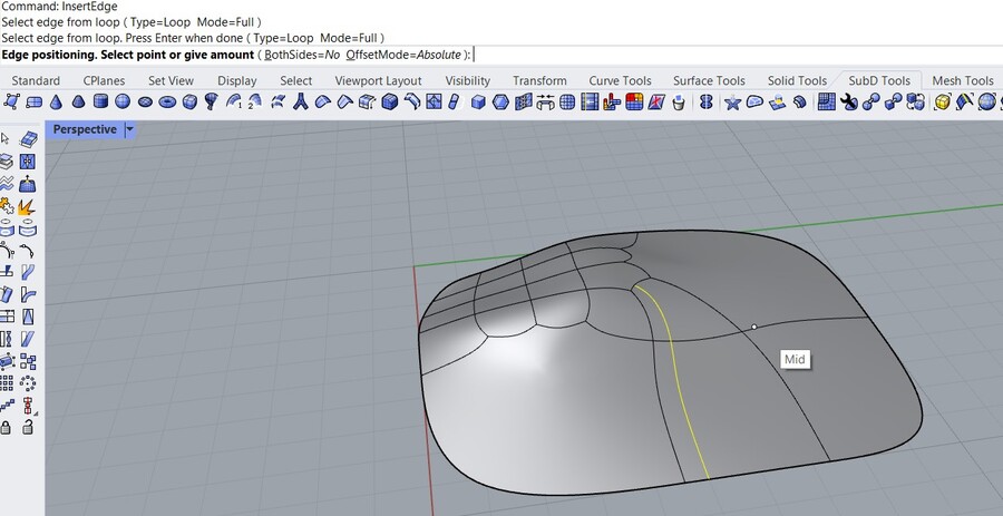
With InsertEdge you can place edges in more specific areas (Osnaps are again very useful, and also look at the modes next to the command). Move edges with the SlideEdge command.
- To only pull at the plane you selected, pull at the little circle instead of the arrow on the Gumball (otherwise all surrounding planes are in the zone of influence)
-
Length: check length of edges

-
Distance: to measure between points
- In the properties on the left you can find the type of object
With this minimal knowledge I had my first go at modeling a mask as seen below; I used mostly the ctrl + shift + click dragging in combination with typing numbers to set it to specific sizes (although it also snaps to the grid which is in centimeters), and used Subdivide a few times; at some point I couldn’t pan anymore for a few seconds which you’ll notice too but it worked again after clicking shift + ctrl again in combination with the panning button (I think that was the solution, I was kind of mashing buttons). After that I exported the head with Export and selected obj (mesh).
This video is sped up with ffmpeg from 12,5 minutes to 22 seconds and went from a whopping 195mb to 1,37mb (!!!) with ffmpeg -i rhino.mp4 -filter:v "setpts=0.03*PTS" rhino2.mp4 followed by a ffmpeg -i rhino2.mp4 -vcodec libx264 -b:v 500k -vf scale=-2:500 -an rhino4.mp4. I love FFMPEG.
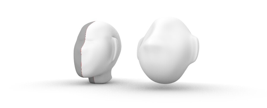
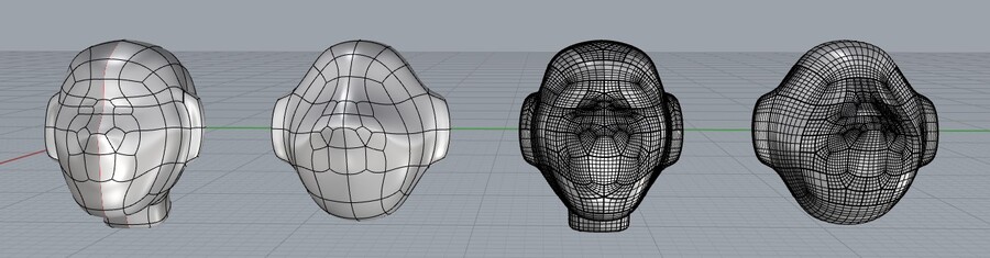
Then I made another one (I first copied the one I had made to the right, Aslı told me it that’s what she usually does to keep originals) but this time with symmetry enabled because I was doing some things twice; the command is Reflect > selecting to points to be the plane or selecting the X or Y axis; the arrows indicate which side to keep. My model changed a little bit near the nose so it wasn’t perfectly symmetrical (but now it is). The symmetry also made it easier to experiment with scaling, rotating, moving and extruding the object without having to keep track of what I had to do to replicate it on the other side.
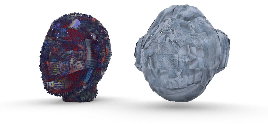
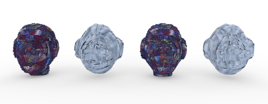
This is my second iteration next to the first iteration in the viewport render mode:
Materials
After seeing them together like this I also wanted a render with some nice materials, so I checked out this quick tutorial.
Steps:
- Go to material tab on the right (little paint tube)
- Click the plus icon
- Add some materials
Substance Alchemist
I saw the option to import materials, so I wondered whether it would be possible to add materials made in Substance 3D and it is! I’ve made Substance materials in the past with the Substance Alchemist Image-to-Material (AI powered) feature so I tried importing some of those.
Steps to install the plugin:
- Tools > Package Manager
- Search for SubStanceImporter
- Click Download and Install
- Restart Rhino
Then go to materials again, click the plus icon and click import from material library and select a .sbsar file. I have both custom and downloaded materials; I now realized that most of my materials were exported as .sbs instead of .sbsar so I decided to open up Substance Alchemist (after closing all other programs, my computer can’t really handle it too well). I exported some of the materials and went back to Rhino.

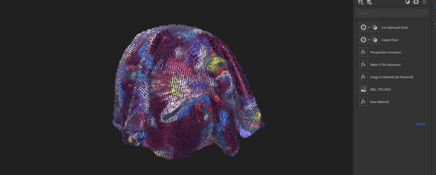
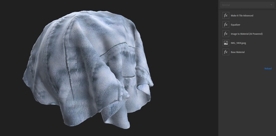
In Rhino, you can change the scale of the texture easily by selecting all associated maps in the textures tab (add it by right clicking the tabs on the right side). I unchecked embed sbsar file because it was pretty big, (that probably means that I have to insert my hard drive if I want to open this file again). In the viewport render it looks fun (patchwork!), but also not how it’s supposed to look:
I converted the SubD surfaces to NURBS with ToNURBS to see if that was the issue, but the material looked the same.
Rendering
I am happy to see that Rhino works very well with displacement maps at least (note that if it looks bad, you can lower the render mesh settings in the properies for a selected object). In the Raytraced view you can render with Cycles, a real-time raytracer; it stops rendering when it reaches the sample restriction. If you don’t change it, it’s set to a 1000; this took about 9 minutes to render (I did screenshot and compress it after so it’s not really here in all its glory). With ViewCaptureToFile you can save it properly but Rhino stopped responding after that, so let’s leave it at this for now.
Grasshopper
Although I find SubD really cool and useful, I also want to learn the ‘traditional’ Rhino; SubD is a pretty new feature and I want to get familiar with working with NURBS too, as well as working with Grasshopper because for next week I’m going to need it.
Grasshopper is a visual programming language and environment in Rhino that works by placing nodes onto a canvas and linking their inputs and outputs to create and modify geometry. You can link to geometry in Rhino in Grasshopper, and you can bring the generated work in Grasshopper back into Rhino. Working with these generative algorithms, you can make endless variations based on as many variable parameters as you want.
I’m going to start with following along with this Grasshopper tutorial and summarizing the steps.
Sphere
- Type Grasshopper into command window
- Add Sphere surface by double clicking the Grasshopper screen; in the Rhino 3D view you can see a preview

- You can see inputs and outputs: for a sphere the inputs are base and radius and the output is a surface geometry; base is 0,0,0 if it’s unspecified
- Hover over inputs and outputs to see what values are expected
- Create a number slider by double clicking and typing a number (if you want decimals, add them!)
- To change the range of the slider simply right click and change the values
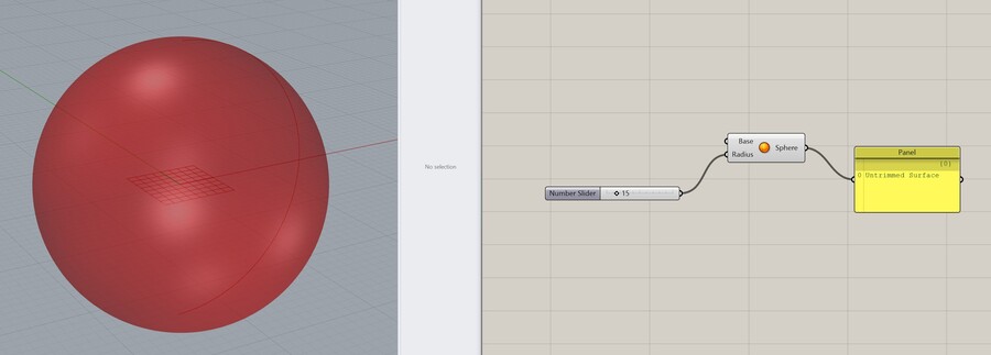
- Link nodes by clicking and dragging from the little protruding circles at the inputs and outputs
- Add a panel to type notes, values or to see the output in text
- You can link Grasshopper nodes to Rhino objects, this is how you can create parametric relations
- If you wanna add multiple inputs to a node, hold shift
-
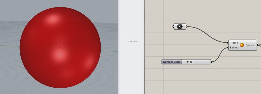
You can also add nodes that reference geometry in Rhino, like a point that you drew somewhere. You can then use it as input for other nodes.
 The center of the sphere is now linked to the point in Rhino.
-
The object now isn’t anything yet in Rhino except for a preview; to turn it into an actual object you have to bake it. You can do this by right clicking the sphere node and clicking bake. You can also select multiple items. The baked object has no parametric relationship to the Grasshopper sphere! You can make a bunch of iterations really quickly like this.

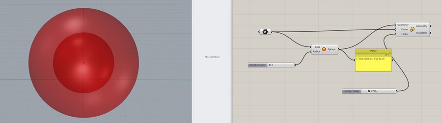
- With a scale node you can make another object based on the sphere
Voronoi
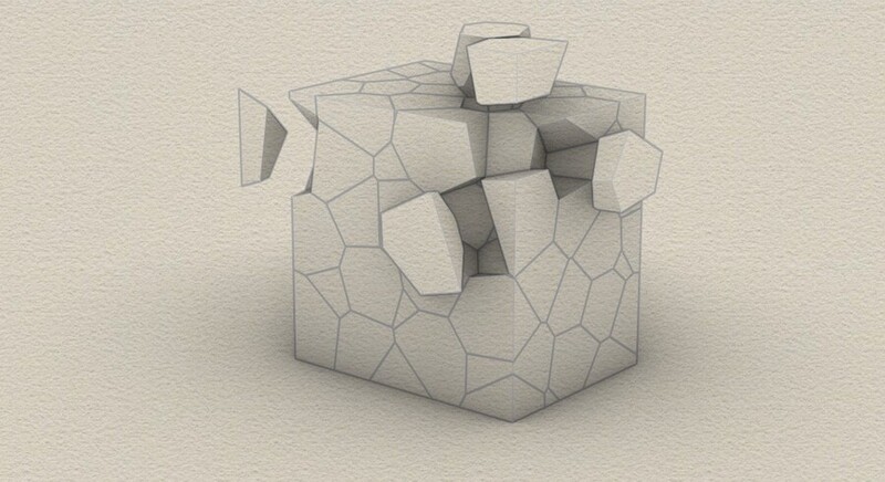
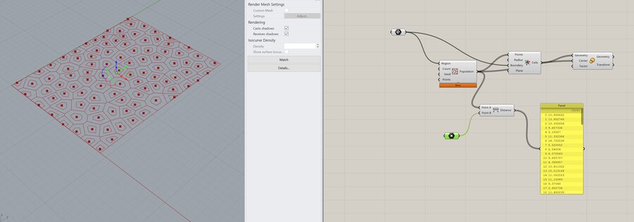
Voronoi is a really cool celular structure that is easy to make with Grasshopper with the Voronoi and Voronoi 3D nodes. You populate a grid with points, then you use those points to create cells around them. If you add a slider for random seed input you can get many different variations.

With Voronoi3D you can do the same as above but in 3D. The Profiler shows you what makes your computer slow; it turns red when it’s a cause of slowness (see red rectangles under nodes).

When you bake the shape you get all of the pieces (closed polysurfaces) separately as a kind of Voronoi puzzle. This is the view with display mode set to ‘Artistic’.
Attraction points
You can make an attraction point with a reference point and calculating the distance between that point and the points in the populated grid. In the panel you can see the calculated distances.
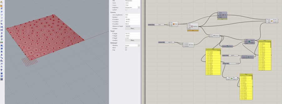
The distance is then multiplied by a small number under 1 (we don’t want it to be larger than the original cell size) to make the cell smaller when the attraction point is closer. If you move the reference point, the Voronois scale accordingly.

I also played around with extruding the resulting polysurfaces (I didn’t find a way yet to autoclose them all yet, the top right one I close with PlanarSrf in Rhino but you have to select the edges manually; I don’t think this is the right workflow for that).

Bounds will tell you the range of values that you’re outputting. If you wanna squish this down you can remap it with Remap Numbers.
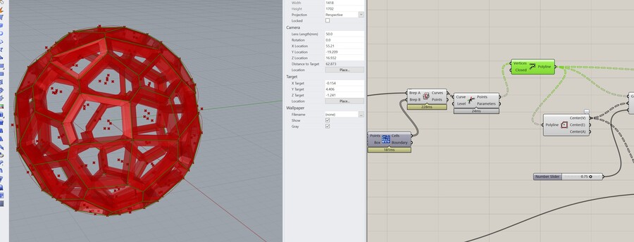
Voronoi 3D
I wondered how to create a voronoi structure around an object instead of on the inside of the object that would be 3D printable and found this walkthrough. I think it would be fun to try to use this technique on a mask (for example made with the heads I made before as a base).
Now that I made this Voronoi sphere, I tried applying it to my head from the previous step, and it was pretty easy. First I tried manipulating the SubD with a scaling node to test the connection.

I had to convert the SubD into a Brep because the populate geometry 3d node only works with surfaces, meshes, curves and Breps.

Then I wanted to turn the baked closed solid polysurfaces into one solid polysurface, because now I’m getting an X amount of polysurfaces (for 3D printing it’s fine though I’ve read). The Join command didn’t work because it’s only for open objects so I looked it up and someone on a forum mentioned Boolean Union. That failed. Grouping them did work so I could at least move the mask out of the way before I made a new one, otherwise selecting the entire mask would be very annoying. The steps mentioned here can work, although Rhino stopped responding so I stuck to grouping. Grouping is also possible when you bake from Grasshopper if you check it in the popup from Grasshopper. Below some iterations in the rendered view (with different materials assigned to each; the red one is the Grasshopper preview):

Here is the 3D model of the last iteration via Sketchfab:
Plugins
I noticed in the tutorials that a lot of people had the titles of the nodes in Grasshopper written above them. I couldn’t find the option anywhere in the menu so I looked it up and it’s a plugin called Bifocals or Sunglasses. I downloaded Sunglasses from
I double checked my documentation from then and I followed the exact steps I’m following now (I should’ve read my previous documentation before I started). They didn’t work though, I think because they are for Rhino 6. I moved Sunglasses.gha into the Components folder, unblocked it in properties and restarted Rhino and Grasshopper and Sunglasses was automatically activated.
Illustrator & Rhino
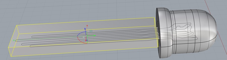
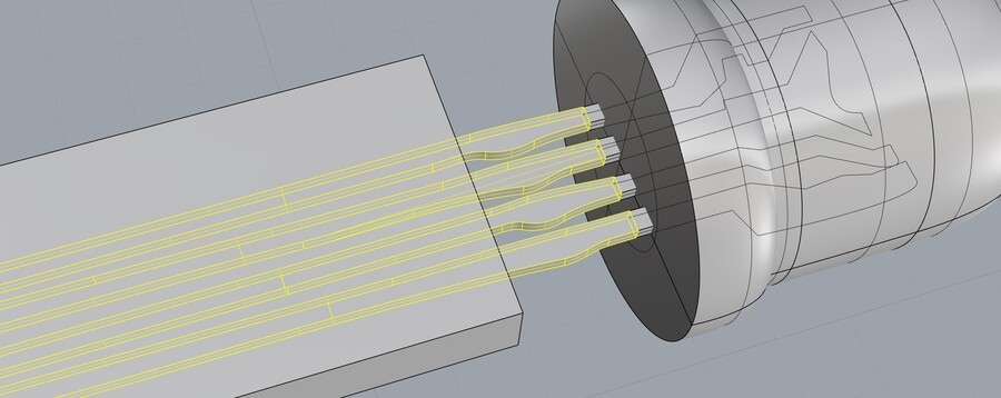
I want to make a simple model of an RGB LED including the inside, so I can import it as a button in CLO3D (more on that later). For this I’m going to use Illustrator in combination with Rhino. I think it’s easier to just use Image Trace in Illustrator to get the outline that I want instead of drawing everything manually in Rhino. I traced the LED with the Silhouettes setting, slid the slider until I was content, then expanded the shape, removed the compound mask, inverted stroke and fill, set the stroke to 0.25, cut off the legs from the LED top, hand drew the insides with the pen tool until they were closed, did the same for the LED then cut it in half (I want to do a revolve in Rhino so I figured that it would only need a half). Then I exported it as an SVG.

I then imported it into Rhino (Import command) and scaled it down until the LED was about 5mm in diameter (the radius was 8.99mm, so I scaled it down with factor 0,278).

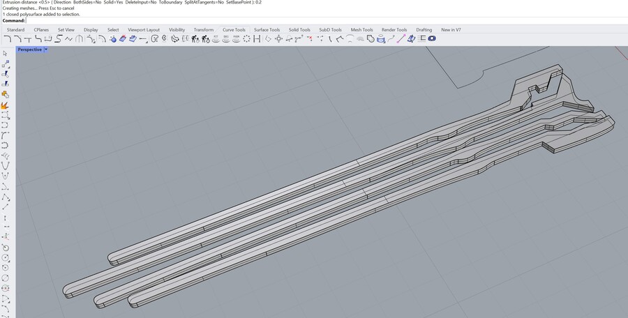
Then I wanted to extrude the legs, but using ExtrudeCrv just like that only extruded the curve too. PlanarSrf (suggested here worked, works for planar curves). Then I used ExtrudeSrf to give the legs thickness. However that only extruded the side anyway. Then I tried again and I saw that in the command was the line Solid = no, so I typed S and enter, and then it changed to Solid = yes and it created a closed solid polysurface.
After that I went to the LED, my guess was that the command for revolving the LED half would be called Revolve so I tried that and that worked. I set the axis to revolve around to the inner straight line of the half, and clicked on FullCircle in the command, and I got a closed solid polysurface as a result which was nice. Now I need to find out how to center them; I could move them but I wanted it to be precise (and it feels like cheating). This was the Align command. I grouped the legs, then selected the head and the legs, typed Align, and clicked on VertCenter, and clicked where I wanted to move the LED to.

The model can be found on Sketchfab here:
I also wanted a version with the legs mostly chopped off, because that’s how I want to use them in CLO3D. In Fusion you can use Combine to subtract solids, so I think it will work similarly in Rhino. I thought it would probably be called boolean (because combine is a really stupid name) and I found the confirmation here; so I made a box in Rhino that I wanted to use to subtract the legs (I had to disable grid snap because my object is really small). I used BooleanSplit.
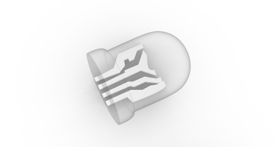
Then I gave the legs a metal material and the top a glass material; this is what that looks like in the Rendered view; after that I exported both of them as obj.
Opinion
Since I have a bit of experience modeling in Fusion360, it wasn’t too hard to get into Rhino modeling. Although both work very differently, many things that I would look for in Fusion are named similarly or can be achieved similarly in Rhino. Working with Grasshopper seemed a little intimidating at first (even though I tried it out a couple of years ago) when you see someone’s finished node tree, but it’s really step by step reading what everything is doing. I think when you’re working step by step and constantly adding a small new feature can make it way more manageable, that’s why following along with a walkthrough is really helpful. When you have something working it’s pretty doable to keep adding nodes with small iterations. One note on my setup: when I started Grasshopper I immediately brought my external monitor back to my desk because my laptop screen alone was very annoying. This also allowed me to better follow along with tutorials so I think I’m keeping it on my desk for a while.
CLO3D
I wanted to make a 2D pattern of the mesh, so it would also be possible to (laser)cut the pattern out of fabric so I can stitch it together and test the shape. For turning 3D shapes into 2D patterns like this, I use either Slicer for Fusion360 or CLO3D. CLO3D is more suited for this purpose because Slicer can only make low poly foldable patterns based on the mesh; CLO is software specifically for pattern making.
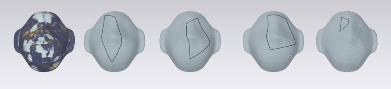
When I opened the head meshes into CLO3D I tried using the 3D pen on them, but that really didn’t wanna work, it would only let my draw very short lines. I tried subdividing the mesh, exporting from Rhino again, exporting as fbx with the highest polygon count possible, scaling up 10x & subdividing that. I tried it on a CLO avatar, and there it worked like it was supposed to.
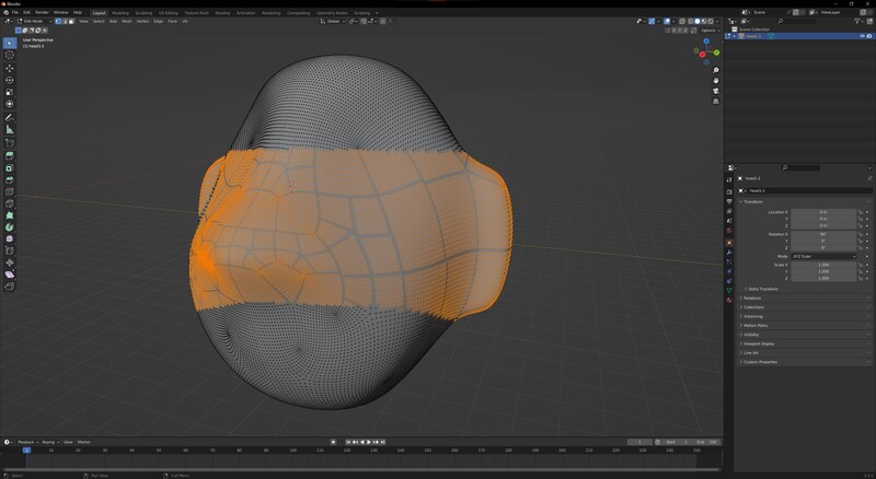
I did notice something interesting about the mesh created by Rhino; you can see the direction of the triangles change in a rectangular patchy way, in the same spots that the materials that I tried to add formed a patchy pattern. Here you can see what that looks like:

Remeshing
I’ve had to fix many meshes exported from Fusion360 (meshes from Fusion are annoying to work with if you forget to limit the lenght of vertices, especially if you’re trying to do displacement mapping) so I have some tricks to fix meshes. When I tried to remesh it with InstantMeshes, the mesh looked strange, as if it wasn’t actually closed.

In Blender it was similar when selecting points or vertices (with face select mode it looked fine). I suspect it has to do with SubD objects.
Blender
Below are some of the options for remeshing in Blender. Select the object and go to the modifiers tab on the right, click Add Modifier > Remesh. Make sure to not accidentally give the mesh a really high resolution because Blender will probably crash.
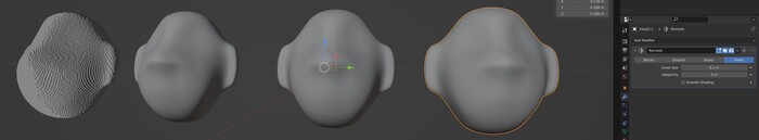
From left to right Blocks - Smooth - Sharp - Voxel. Then I applied the changes so it was easier to see the mesh in edit mode. I exported the heads as an obj again and imported them into CLO3D again (I flipped some values in the obj export so that’s why they’re all mirrored). And now the 3D pen works! The blocks one doesn’t work too well but that was expected, the mesh is very bumpy.
Notes:
- Here is a link to my Blender notes, here some more on displacement mapping.
- View > Frame selected (if you’re on a laptop like me, otherwise numpad + .) when you’re completely lost in space trying to find your object
3D Pen
I exported the voxel remeshed head separately, and went in again with the 3D pen. Some notes on drawing on an avatar with a 3D pen:
- Just clicking makes a straight angle, ctrl + click makes a curve
- Hold shift to make a 90 or 180 degrees angle
- If you accidentally intersect a line you’ve already drawn, you have to start all over again with that line
- Don’t forget: 3D Pen (Avatar) is for avatars, 3D Pen (Garment) is for garments
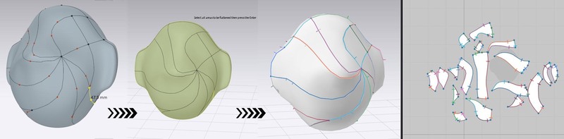
- Flatten to make 2D patterns out of the 3D
On the left the avatar with the 3D lines, in the middle the Flatten operation in action and on the right the generated 2D pattern in the 3D view and 2D view and automatically sewn together:
I then played around with some fabrics from my fabrics library, I’ve downloaded fabrics from the CLO-SET library and I’ve made plenty of fabrics in Substance and with Photoshop that are all there.

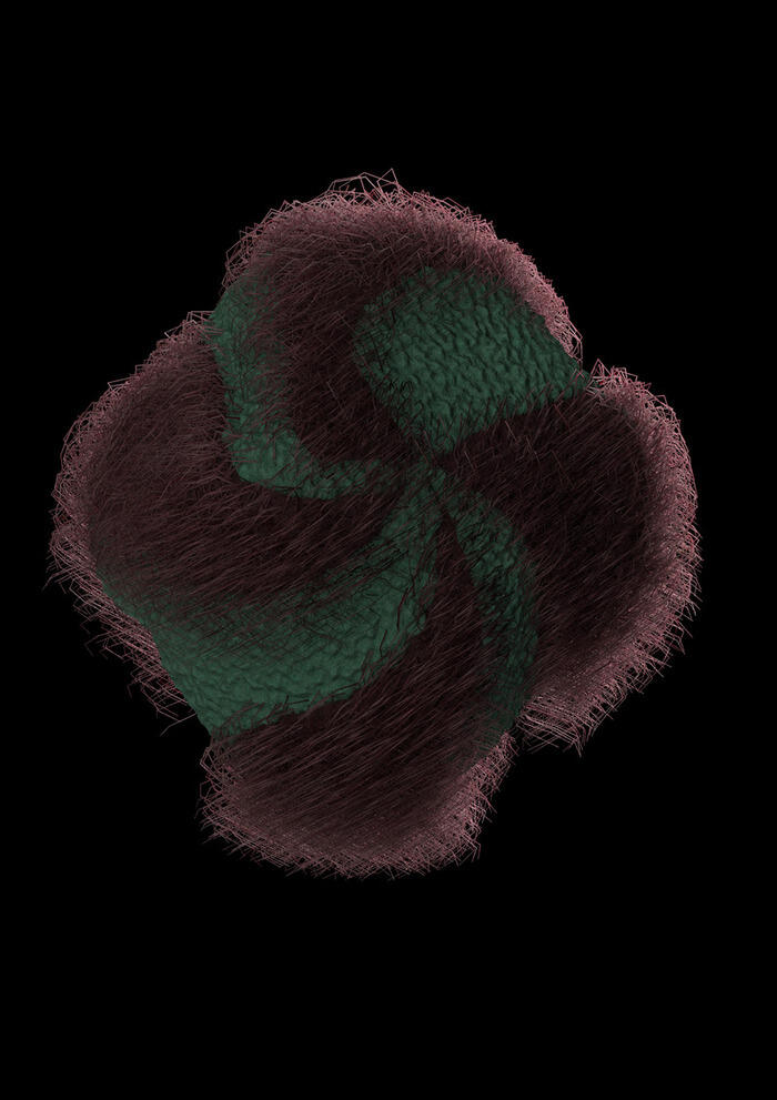
You can render all kinds of fur-like fabrics in CLO, and there are a lot of parameters that you can change to make weird custom fabrics.
2D pattern & buttons
For the second head I made in Rhino I had another plan; I wanted to try using the RGB LEDs as buttons in CLO3D because it’s a convenient way to place small objects onto a 2D pattern, and I remembered CLO has a material option called ‘light’ so I thought I could use it for realistic rendering of the LEDs. I’ve made custom buttons in the past and anything can be a button in CLO; you just have to load an OBJ and set the correct scale, and place them where you want on the surface.
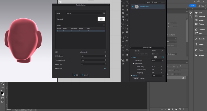
You have to be careful with buttons because they tend to be messy; I countered this by turning off collision in the property editor on the right. On the left is with collision on (I stopped simulation before it went too far), on the right with collision off.

There is a sort of version history in CLO3D called 3D State. If you want to save the current version of your design in the file, you can make a new 3D state and then you can always open that version again.

Placing the buttons is quite a tedious task, even if you don’t have to place them all separately. I only did the front for now but if I am going to make a mask with light (the proud mask idea that wants to stand out in any environment by always showing the opposite colors of its environment) I would want to have it all over the head.

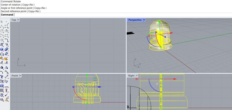
I had to go back to Rhino to change the orientation of the button because it wasn’t intersecting with the Y axis. Then I had to go back again because the button was not oriented perpendicular to the fabric.
I made some renders:
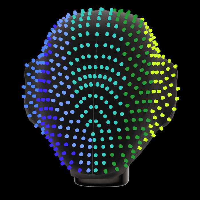
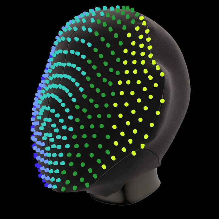

Final turntable animation render (in gif form made with the online tool ez-gif):
And here the 3D model:
Opinion
I’ve been using CLO3D for 2,5 years now, and it’s kind of love and hate. I work with it a lot since my background is in fashion design, but the documentation is absolutely terrible. CLO doesn’t really have a visible online community like Blender has. I know there are a couple of independent Discords that you can ask questions in but if you don’t want to do that you’re kind of on your own. If you want to use CLO3D you definitely need a computer with a good CPU and GPU (although I noticed that CLO3D doesn’t use my GPU very much).
MakeHuman and Blender
I also tried some sculpting with a model that I quickly made in MakeHuman: an open source tool to make human models. I find that the models look pretty questionable, but if you need a quick human model it can be pretty useful. You can change the model with all of the provided sliders or you can add specific measurements. You can also work with a script if you need a thousand different models. I moved some settings around then exported to obj.
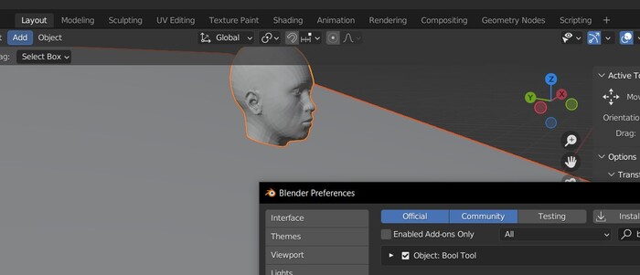
Then I imported the model into Blender and cut off the head using a boolean difference (first I had to enable the bool tool plug-in) and added a subdivision surface modifier (subdividing the triangles/quads to get a smoother mesh).
I tried a couple of sculpting options but found the result a little disturbing so I left it at this. When you export a model from MakeHuman, it comes with eye sockets and eyes, so they got quite deformed. One way to counter this would be to do a boolean union between the eyes (made slightly larger so it intersects with the mesh of the head) and the body.

Opinion
This week I didn’t do a lot in Blender because I wanted to focus on Rhino and Grasshopper. I like Blender because it’s very versatile and open source, but I mostly use it for very specific things. I have a workflow for displacement mapping meshes for 3D printing, and I like to use it to remesh meshes. At my work at a textile workshop we use it to target motion capture data to models for use in CLO3D (it doesn’t work super well though). For Fabacademy I think I won’t use it too much, because it’s mesh based modeling. I can imagine that I’ll use it to fix meshes exported from Fusion or Rhino though.
Photoshop
Since we also have to do something with raster based software this week, I figured I would show what I did with Photoshop this week. I don’t think it’s useful for me to do go into all of the features of Photoshop because at this point I’ve been using it for almost nine years, but I might look into some of the newer features (neural filters etc.).
This week I used it to place images next to each other and add arrows by adding the images in one file (multiple layers so I can move them around individually); I used a Multiply blending mode on the arrow because I found it online and it was a jpg with a white background (when using multiply, whites become invisible). Then I flattened the layers and saved it.

Files
- Voronoi 2D Grasshopper file
- Voronoi 3D Grasshopper file
- Voronoi 3D Mask Grasshopper file
- RGB LED
- RGB LED with chopped legs
- LED parts SVG
- 3D models on Sketchfab
Lecture notes
2D design
- Drawing in traditional media and scanning it
- Raster: storing dots
- GIMP: open source image editing program
- Photoshop: commercial image editing program (the one I’m using)
- Photopea: free online tool that resembles Photoshop (mentioned in lecture chat)
- Vector: storing shapes
- Inkscape: open source vector program (I use it sometimes)
- Illustrator: commercial vector program (the one I’m using)
3D design
Declarative: you describe the constraints/applications of the design, often done with code/scripts
- FreeCAD: open source 3D design tool, starting with a 2D sketch that you can add constraints to (I think a similar workflow to Fusion)
- OpenSCAD: declarative
- Blender: open source program in which you can do great rendering and animation, as well as modeling and sculpting. For organic shapes, this sculpting is really nice. There’s also a CAD Sketcher plugin in development which is really cool
- ZBrush: commercial sculpting tool
- Rhino with Grasshopper: commercial, node-based designing (this is the one I wanna learn during Fabacademy)
- Fusion360: commercial, has a timeline so great for parametric designing (I’ve been using this for a couple of years now)
- Solidworks: commercial, great for collaborating on projects
- Onshape: free and browser-based modeling, great for collaborating too
- SculptGL
FreeCAD
- Snapping: ways to make relationships, great for precise positioning (which is hard to do with just a mouse)
- Containers: objects that house multiple objects
- Symmetry is very important
- Most important: parametricity! In FreeCAD this is called a spreadsheet, here you can add variables (numbers or formulas)
- Workflows:
- Starting from 2D sketches and then extruding/revolving/lofting/etc
- Starting with 3D shapes and using boolean operations. You can also fold and unfold
- 3D to 2d with:
- projection (for lasercutting)
- slicing
- You can made drawings of your 3D files (just like in Fusion) for visualization
- You can also render directly in FreeCAD (moderate quality, Blender is better and realtime)
- Animation is also possible, you can animate using nodes
- Some extra notes taken when Pieter gave us a demo:
- You can make a spreadsheet with parameters
- Workbenches such as Sketcher and Part Design (different ways to do assembly)
- You can make custom workbenches and you can download workbenches for specific purposes (i.e. BIM)
- You can design parts in the orientation that they have to be manufactured (for cnc machining for example) and then assemble them how you want, but still have the individual parts oriented correctly automatically when you need them to be flat
Physics
- Blender physics engine is really good for realistic animation
- Fusion has really good physics too (finite element analysis: FEA)
Video & Audio
- Hour-long videos can be linked, short videos should be in the repo
- Kdenlive: open source video editor that’s pretty powerful
- Audacity: open source audio editing tool
- FFMPEG: command line tool for compression and conversion etc.
AI tools
- Available for 2D and 3D as well as text (can be ethically dubious though because a lot of art is being used without permission to feed the AI)
- 2D: Stable diffusion, DALL-E, Midjourney
- 3D: Magic3D, Dream Fields, Dreamfusion
- https://make-a-video3d.github.io/
- https://www.kaedim3d.com/ (light version is 599 dollars per month though)
Global Open Time notes
- Decimate Modifier in Blender can help with making files smaller
- Ricardo’s tip: “if anyone wants an easy GUI way to compress some videos I used Handbrake with this preset”