Computer-Controlled Cutting
This week is all about lasers and cutters. I expected this week to be a breeze, but I was caught off guard by my struggles with Grasshopper. Let’s say I learned a lot.
Laser cutting
General
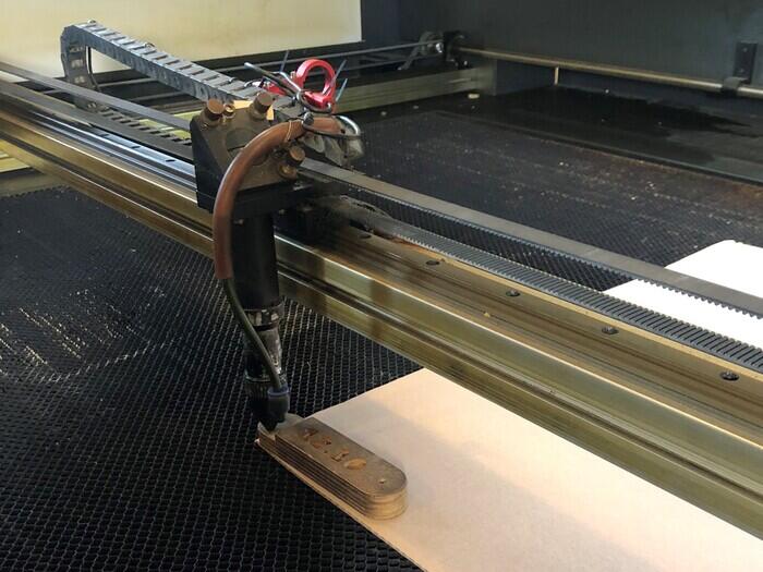
The laser machine we have in the lab is a 100 Watt BMR 1612 CO2 laser cutter. This CO2 laser is produced in a glass tube behind the laser cutter. The laser beam travels through two mirrors from the back left to the start of the axis the laser head is located on, then through a third mirror on top of the laser head reflecting the beam down and then through the lens in the laser head. The controller board is a Ruida 644XG, which is an upgrade to the original board that came with the machine; Henk upgraded it 2 years ago.
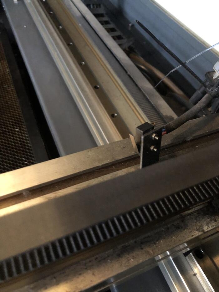
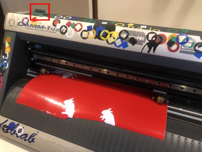
The red thing that is tie wrapped to the chain on the X axis is an auto leveler that doesn’t work, so it’s moved out of the way for now.
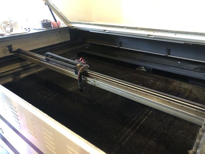
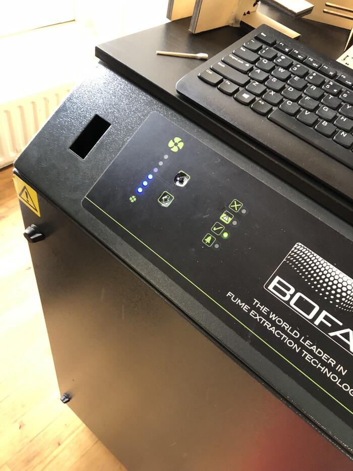
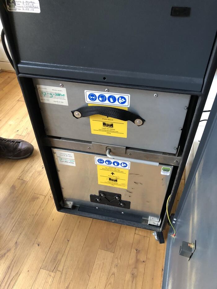
It has a working area of about 1200 by 1600mm. The bed consists of a honey comb grid, through which the fumes are extracted with the fume extractor connected to the bottom of the laser. Tiny lasercut parts also fall through it, so from time to time it should be cleaned. The fume extractor is a BOFA AD Oracle with a HEPA filter in the bottom; the top filter is for big particles.
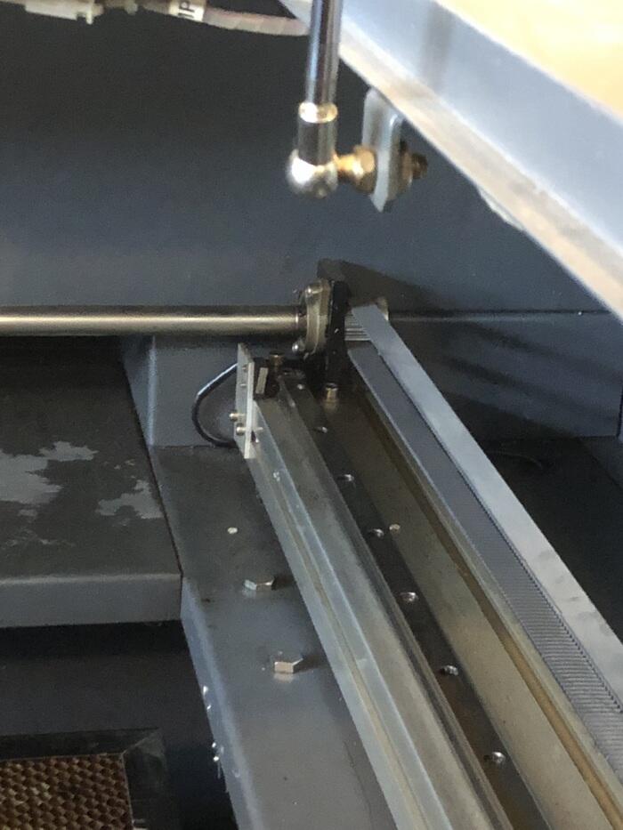
There are two end stops: one on the right of the beam the laser head is on for X axis homing, and one in the back on the right for Y axis homing. Every time the machine is turned on, it will home both axes and then return to the position it was last in.
The laser cutter is cooled by water in the back. This is distilled water that is flowing when the laser is on. Next to it you can find the power plug for the fume extractor; the on/off switch broke so it’s hardwired for now.


Laser head assembly
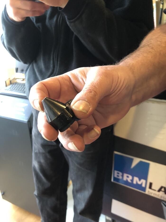
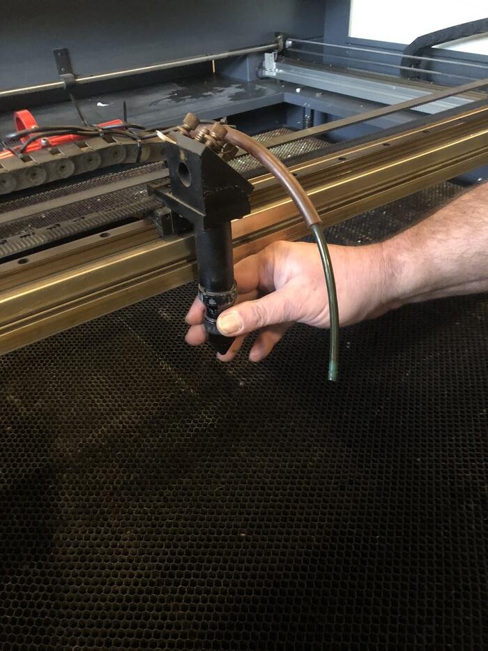
The laser beam goes trough the laser tube in which the lens is located, then through the laser tip and through your material. Keep in mind that the laser tube assembly is only the housing, you don’t need to tighten it massively. Sometimes it’s being tightened instead of loosened which means it can be very hard to take out the lens for a checkup. You have to loosen it in the opposite direction from what you would expect (not righty tighty, lefty loosey).
You need flowing air to clean away the material and fumes. The tube connected to the laser tip is blowing the air on the material. You can turn this off by turning the valve on the right side of the laser cutter (not in the software because it is hardwired to always blow on the material), but only if you have a good reason to do so. For example when you are laser cutting paper or thin fabric, because it can be blown away by the air; otherwise leave it on.

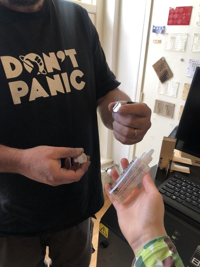
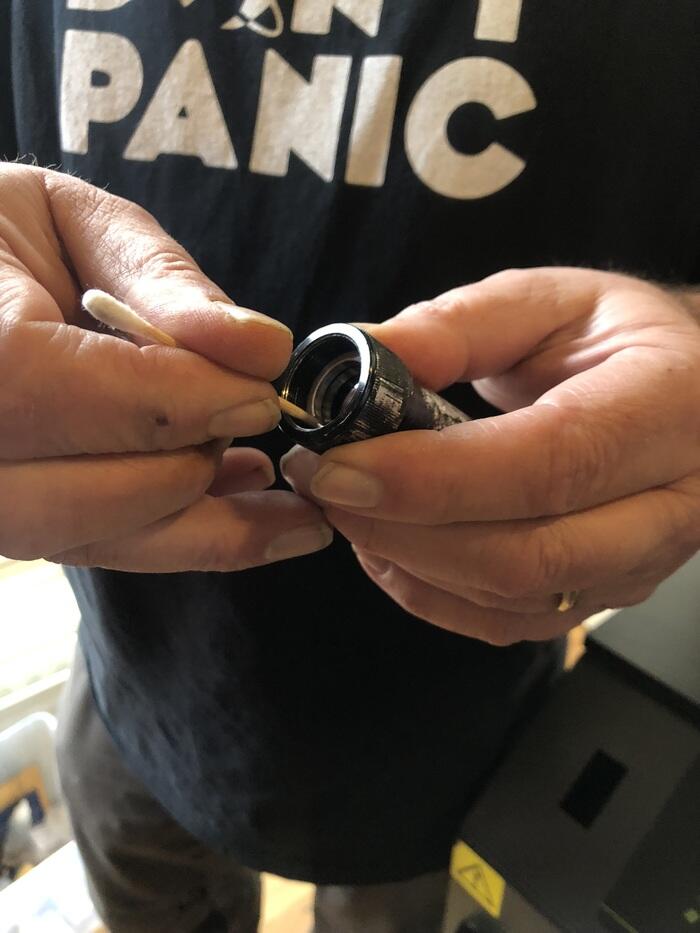
Lens
Once in a while you have to clean the lens; you clean it with alcohol. When taking it out, keep the orientation of the lens in mind: the curved side on the top, the flat side on the bottom. Wrong side up doesn’t work very well so if it was fine and focused before, and after cleaning not at all, then that is one thing to check. Don’t tighten the lens with a screwdriver but use the back of a cotton swab, because you might scratch the lens.
Focusing the laser
The laser has to be leveled on the material every time you use a diffent material. The distance is a constant 12.10mm measured from the top of the material to the bottom of the laser tip. For this we use a piece of wood with that thickness. Something to keep in mind is that the bed is pretty beat up, so it may not be as flat everywhere. Your material can also have variations in thickness or can warp, so sometimes you have to find the best average.

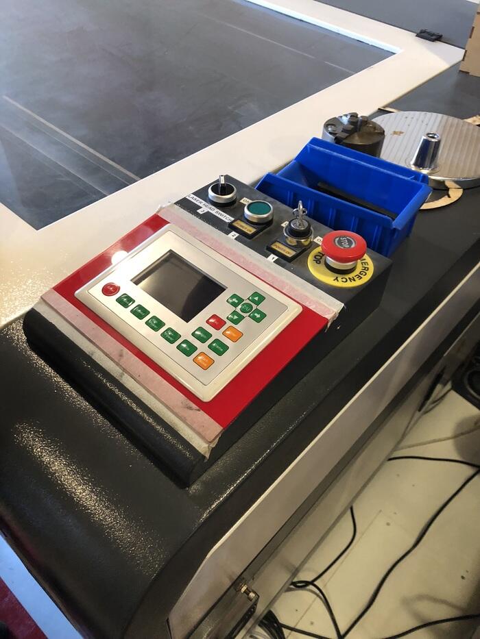
Turning the machine on
When you turn on the laser it first homes itself, then it goes back to the position it was in. You turn it on by turning the key clockwise, then pressing the green button to the left of the key. The laser head switch is left off until you’re ready to start laser cutting.
Lightburn
We use Lightburn to operate the laser cutter. With Lightburn you can import various types of vector graphics and image formats (including AI, PDF, SVG, DXF, PLT, PNG, JPG, GIF, BMP). You can also work directly in Lightburn. There is plenty of useful features such as auto closing open vectors, removing double vectors, boolean operations and alignment tools.
- We only use Current Position as a starting position, which means your design will always be positioned relative to the current position of the laser head.
- Min power is corner power; when the laser head is changing direction it has to decelerate so its better to change
Group assignment
For the group assignment this week we have to:
- Characterize your laser cutter’s focus, power, speed, rate, kerf, and joint clearance
- Document your work to the group work page and reflect on your individual page what you learned
Henk told us that we are not documenting this week to the group work page, so we divided the work and shared our findings with each other in the lab. My task was to find out the laser cutter’s kerf and joint clearance.
Kerf
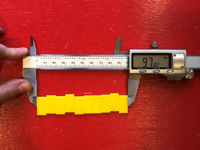
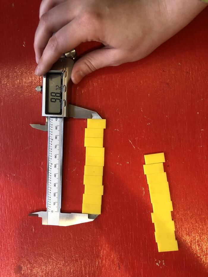
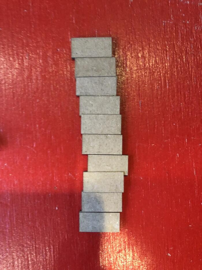
When a laser cutter cuts a line, it burns away material. Because a laser beam has a certain width, you end up with a part that is slightly smaller than you want, unless you account for this. The kerf of a laser is the amount of material that gets burned away To figure this out, I cut out 10 rectangles with a width of 10mm. I tested with three different materials of the same thickness (acrylic, plywood and cardboard).

By using 11 lines, the formula becomes easy as I have 9 inner lines that count for a full kerf, and then two outer lines that I only have to count half of, because the other half of the kerf is made on the leftover material. This means that the kerf can be calculated by dividing the decrease in width by 10. The kerf that has to be accounted for is this number divided by two, assuming that your parts are not lined up exactly next to each other; the other half of the kerf is burnt out of the leftover material.
- Acrylic (first test, two passes: first pass Speed 20 Power 70, second pass Speed 100 Power 80)
- (100 - 98,72) / 10 = 0,128mm kerf
- 0,128mm / 2 = 0,064mm kerf offset
- Since this one was cut twice, and I think the parts aren’t lining up well (the edges were a little rough), I would say this one is not valid, so I did it again.
- Acrylic (second test, one pass: Speed 10 Power 80)
- (100 - 97,82) / 10 = 0,218mm kerf
- 0,218mm / 2 = 0,109mm kerf offset
- Plywood (Speed 20, Power 80)
- (100 - 98,54) / 10 = 0,146mm kerf
- 0,146mm / 2 = 0,073mm kerf offset
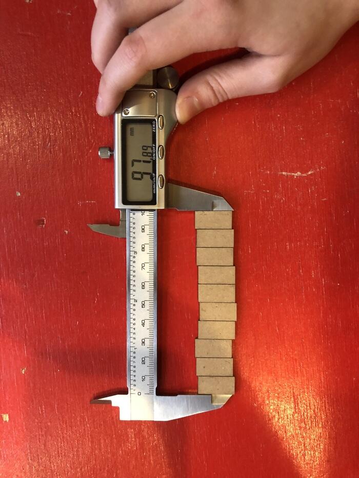
- Cardboard (Speed 50 Power 60)
- (100 - 97,89) / 10 = 0,211mm kerf
- 0,211mm / 2 = 0,1055mm kerf offset
- I cut this one twice as I forgot to take the direction of the corrugation into account
I used min. power 20 for all of them.

Reflection
I do realize that the kerf can vary with different materials and thicknesses, so I would recommend doing a kerf test like this if you are using a different material thickness. However, since it is recommended to do a joint clearance test of some sort when you have to make something that has to be assembled, this usually means that instead of only accounting for the material thickness (and variation in it) and press-fit testing, you are automatically also covering the kerf offset with those tests. The average kerf offset calculated was less than 0.1mm, so if you are using steps of 0.03mm or 0.05mm you are basically feeding two birds with one seed.
Joint clearance combs
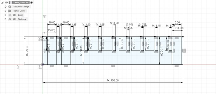
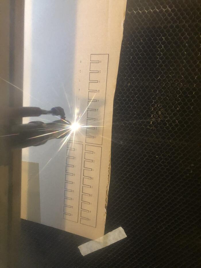
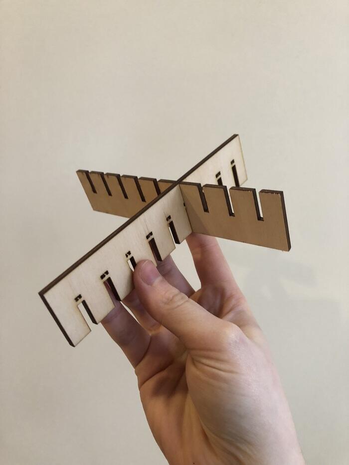
I made a parametric joint clearance comb in Fusion360 and tried it out in 3mm plywood, acrylic and cardboard. The comb can be set to any base thickness and variation in deviation. The text is also parametric so you can see what measurement works right away.
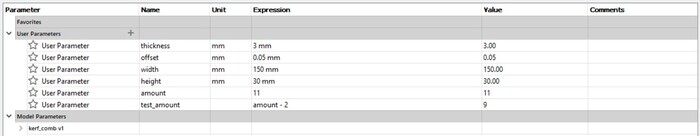
I started out with the following simple parametric sketch and parameters:
ParametricText
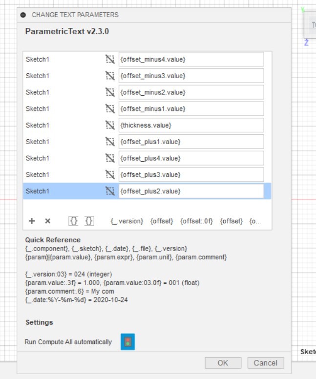
When adding the diameter of the press-fit joint, I found out that I couldn’t make the value of the text parametric. Luckily there was a solution presented here with the ParametricText addon. I downloaded this AddIn here and installed it in %appdata%\Autodesk\Autodesk Fusion 360\API\AddIns.

Then I realized I couldn’t add formulas directly into the ParametricText text fields, so I had to make a couple of parameters to reference.
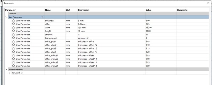
After that it was a matter of linking the text fields in my sketch with the correct parameter values.
And there it is! I made a 1:1 drawing of the top of the extruded model, then exported it as DXF for laser cutting.


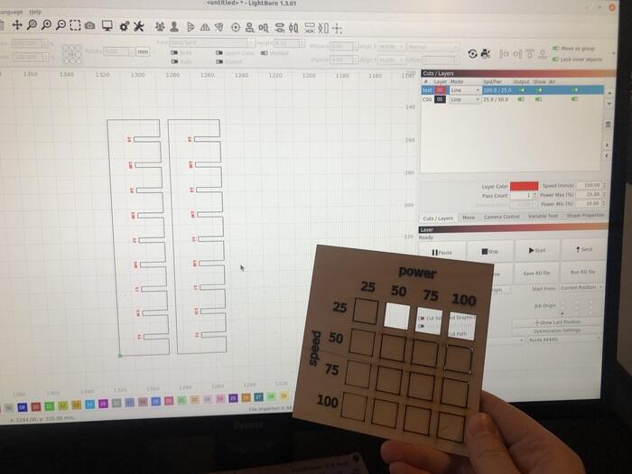
I used the power and speed testing cards that Samson made as a reference for the cutting settings of the combs.
For the cardboard test I made two combs; one with 3.0mm as a base value and one with 2.6mm, because it was a bit thinner than 3mm (about 2.75mm).
Conclusion


- Acrylic (3mm): press-fit at 2.8mm, joint clearance of 0.2mm
- Cardboard (2.75mm): press-fit at 2.50mm, joint clearance of 0.25mm
- Plywood (3mm): press-fit at 2.95mm, joint clearance of 0.05mm
The plywood and cardboard can fit okay in slightly smaller joints, because the material can give a little. The acrylic didn’t feel like that. The smallest fit on the comb was a good press-fit, any tighter and I think the comb would have snapped. That’s why I didn’t cut a second slightly smaller comb.
Individual assignment
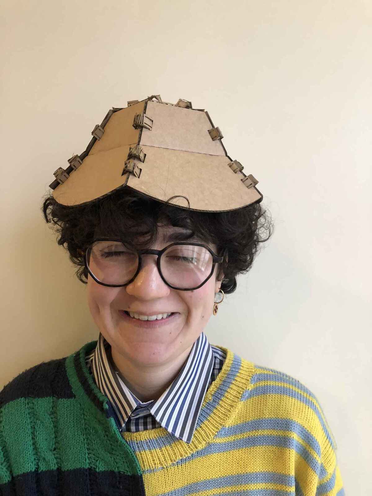
I love hats, so I wanted to make a parametric hat construction set. For this I wanted to use Grasshopper. I started with a lot of optimism because I thought what I wanted wasn’t that hard to do, because I could imagine it pretty well parametrically. It was harder than I thought getting Grasshopper to do what I wanted. most of the commands I used I found by looking up what I expected it to be called, and from browsing through the tabs in Grasshopper. Working in Grasshopper is really breaking up the design and working through it step by step.
Grasshopper
General note: green on the right in Grasshopper means it’s selected; orange on the left in Rhino means that is what the selected node in Grasshopper produced.
Shape of the hat
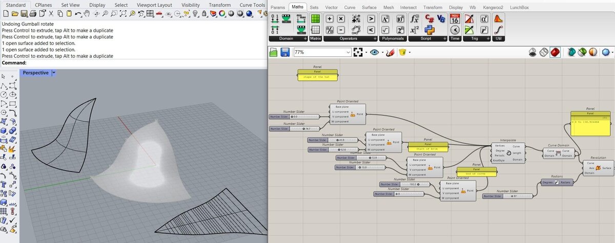
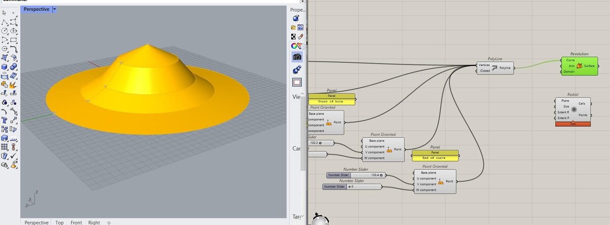
I started out by making an interpolation with Interpolate of four points to determine the shape of the hat. With all of the number slides the curve can be changed.

Then I made a revolution around a central axis. I used a curve domain node in between to check the length of the curve, it doesn’t modify the shape of the curve. If you don’t add an input for the axis, it defaults to the Z axis. A panel of the hat is made with a number slider and a degrees to radians converter, because the domain of the Revolution node expects radians as input. The shape to the left is a baked part of the hat; baking means that you bring the current version of the Grasshopper output to Rhino as an object (depending on from which node you bake it). After that, the baked shape doesn’t have a relationship with the Grasshopper nodes anymore, it’s just a ‘dumb’ Rhino object. On the right is the flattened pattern approximation made with the Smash command in Rhino; this is a command you can use to lay a surface with curvature flat. This is useful for pattern making for textiles or for working with sheet metal.
I then realized that I would have to turn the shape into flat pieces anyway, so I might as well do it directly in the Grasshopper file. I replaced Interpolate with a Polyline to do this.
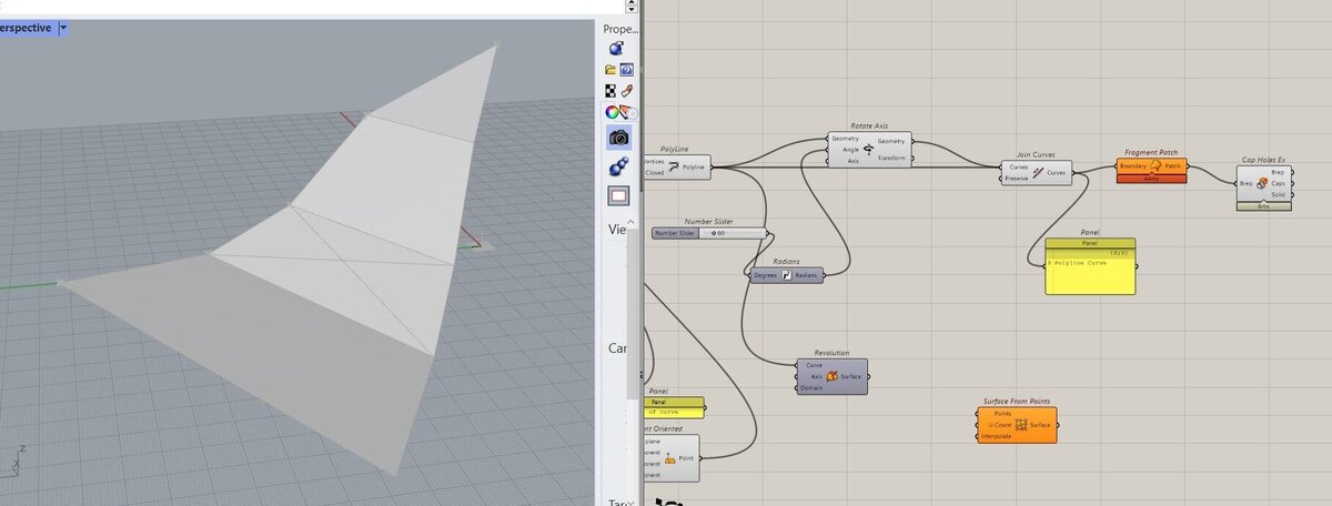
Now the sides of the hat are still curved, which is not what they should be. So instead of a Revolution, I rotated the polyline 60 degrees along the Z axis with Rotate Axis, then I joined the two curves with Join Curves and turned the polyline curve into a surface with Fragment Patch. Cap Holes Ex didn’t do anything.
At this point, I started doubting whether this was a smart way of working. Aslı came into the fablab, and said that it may be easier to work with circles divided in equal parts with Divide Curve, and then use those points to build the surfaces separately. Lists with points should be easier to work with than patched polylines, because then I would have surfaces that I could target easily.
Aslı helped me to build the surfaces from four points by using list and nodes to always get the data that I needed. This was a lot of trial and error, and checking with panels what the output list was. Cull pattern is a method of removing elements from a list in a repeating pattern of booleans (such as true, false, true, false). Shift List is used to shift the indices of a list by a specified number, which is useful if you need to target one point and then the point next to it. Below it wasn’t right yet.
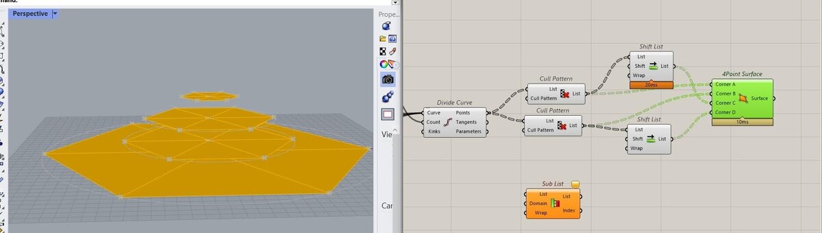
Here it was becoming 3D, but definitely still not right.

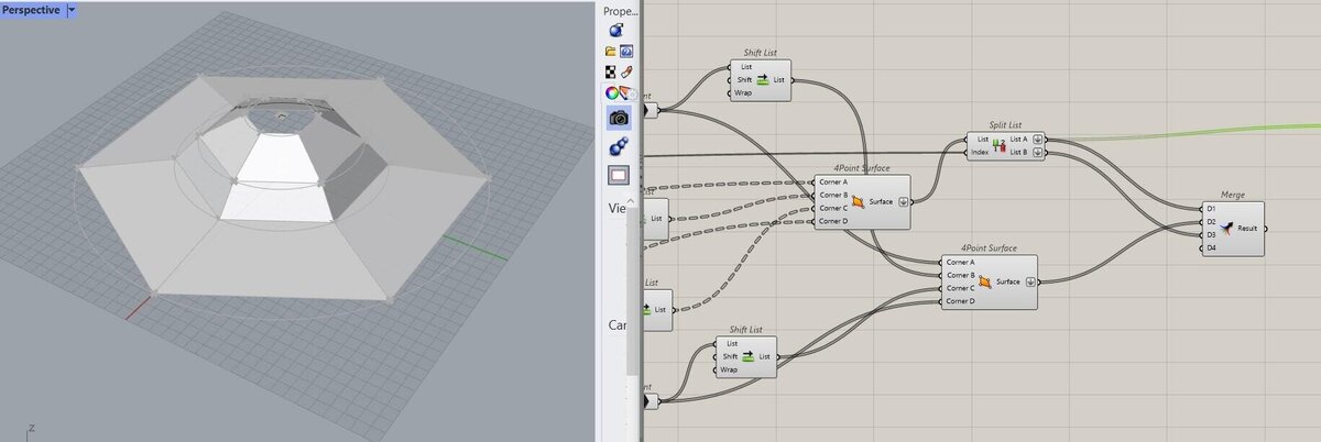
Per Divide Curve node two circles are connected. To split the resulting lists into lists of the bottom circle and top circle, I used Split List. Then the points in the list have to be shifted to get the point next to the previous point to build the surface from four points. It may have been more legible if I had just used four Divide Curves probably, but this worked.

A couple of days after the previous state I cleaned it up slightly; the collection of points wasn’t necessary. I also thought I could get rid of the Shift List, but I forgot that they were there because some of the points needed the shift to build the surface so they had to stay. The four point surfaces are created with two points next to each other from the divided circle (the second point is to the right of the first one), and then the two points below those points selected in opposite direction (so the third point is to the right of the fourth one). So all surfaces are created with four points starting in the top left corner and then moving clockwise.
Then the top and bottom surfaces are split again so the panels can be selected from top to bottom and merged in the correct order. The output of this merge is a list of all of the panels from top to bottom; Merge merges data streams, it doesn’t merge surfaces into a polysurface.

Bendable cutting pattern
I wanted the hat to be a little flexible; even if it may not work well with cardboard, I think a cut pattern on the hats will give them a better look, and I wanted to figure out how to map vector patterns to surfaces with Grasshopper, in such a way that the pattern wraps along the surfaces.
It turned out to take me about 7 hours to figure that out, so instead of a nice spiral shaped workflow it was a stubborn (in too) deep dive. It wasn’t even necessary for the parametric part of the assignment, but I still wanted the cut pattern to be parametric too, so I got stuck on that for too long. Hopefully this is a spiral development lesson for me.
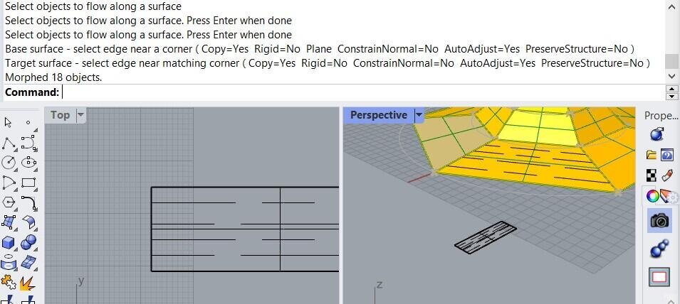
Aslı showed me how to map a rectangular design to a surface with FlowAlongSrf like this:
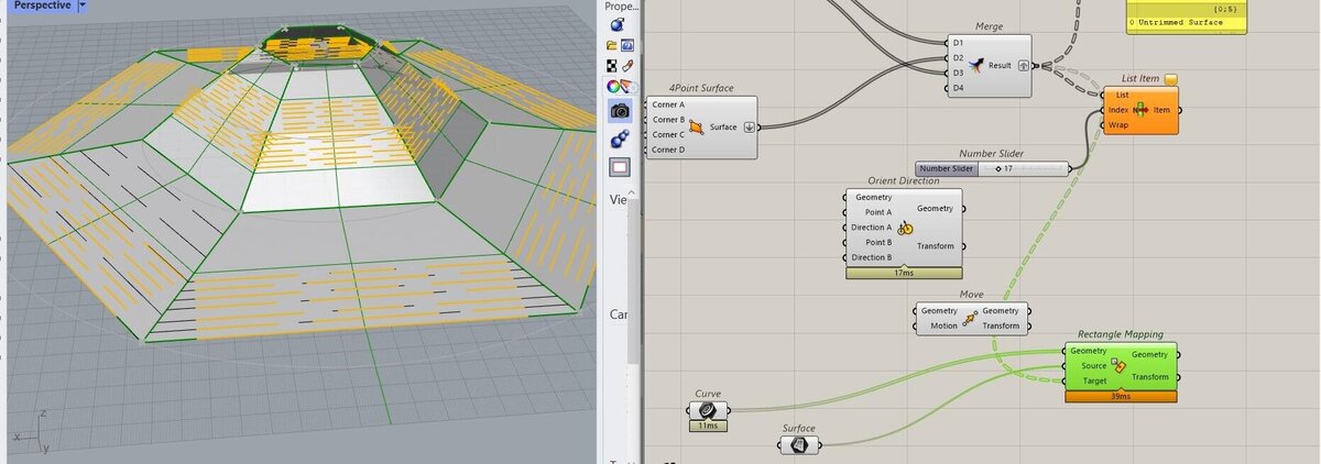
I could’ve left it at that but at this point I was optimistic that I could do this in Grasshopper too, so I went to work. With Rectangle Mapping you can map rectangular geometry onto a surface. I think it’s fine if the geometry is not made in Grasshopper, because this is what I want to play around which is easier by drawing lines in Rhino.
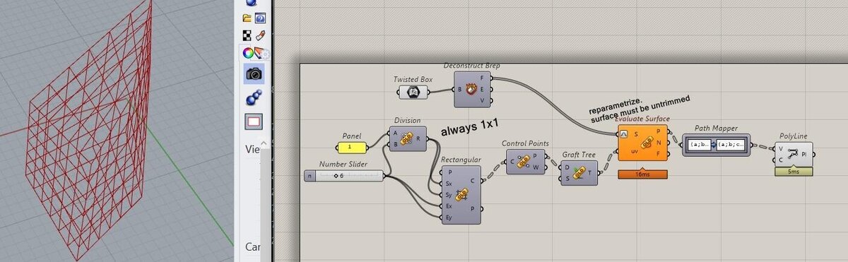
I found this twisted box example with rectangular divisions, and I thought it could help me:
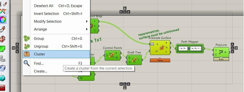
I didn’t know how to open a file within a file (I wanted to open it in my parametric hat file), but I saw this Cluster option and a cluster insert option, so I selected the file and clustered it by selecting everything and right click > Cluster. Then I inserted it into my working Grasshopper file. I didn’t do anything else with it though because I didn’t know how to apply it to my situation.
Then I made some lines within Grasshopper and arrayed them as input for the next couple of tests. I tried Splop on the hat’s surfaces, which wraps geometry onto a surface, but that didn’t work; I didn’t get any output, and I think it wouldn’t have worked anyway, because Splop doesn’t warp with the surface which is what I want. Then I tried Flow which re-aligns objects from a base to a target curve. Here it went a little crazy.

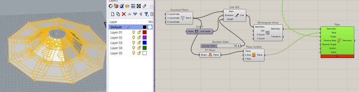
When I made a XY plane surface starting at the first point of the rectangular array, it aligned properly to the surfaces, but the lines looked weird and didn’t stay within the surfaces; rigid was set to false and stretch to true. When stretch is set to false, the lines went even further away from the surfaces, and when rigid was set to true, the lines would look correct, but they would still go over the boundaries of the surfaces. I think the conclusion is that Flow and Splop don’t work for what I want to achieve.
Surface Morph gave similar issues. I tried Sporph but that didn’t produce anything (although I probably didn’t connect it correctly).

When looking for options, I found this Map to Surface option mentioned on the forums, which is part of the Parakeet add-on. I downloaded it and looked through the documentation, and it looked very promising and like a possible solution which I really needed, because at this point I was pretty frustrated; apart from the things I tried above I looked through many nodes and tried some stuff without much luck, and it felt like it wasn’t possible to do something that I thought would be a basic feature. I probably should’ve paused this spiral before I spent 3 hours frantically connecting nodes without fully understanding what I was doing. The possibility to upgrade Grasshopper with some add-ons hadn’t crossed my mind yet.
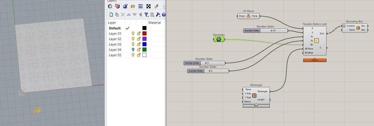
Below an example of a simple tile repeat with a few curves drawn in Rhino referenced in Grasshopper in the Geometry node. If you change the curves, the pattern changes with it, so it’s a fun way of creating nice repeat patterns. Here I just used Tileable Pattern (P4). P4 is the identifier of the type of repeat; there are six options in Parakeet > Pattern Generation.
Then I tried to use Map to Surface directly on the surfaces of the hat, which froze Grasshopper and Rhino.
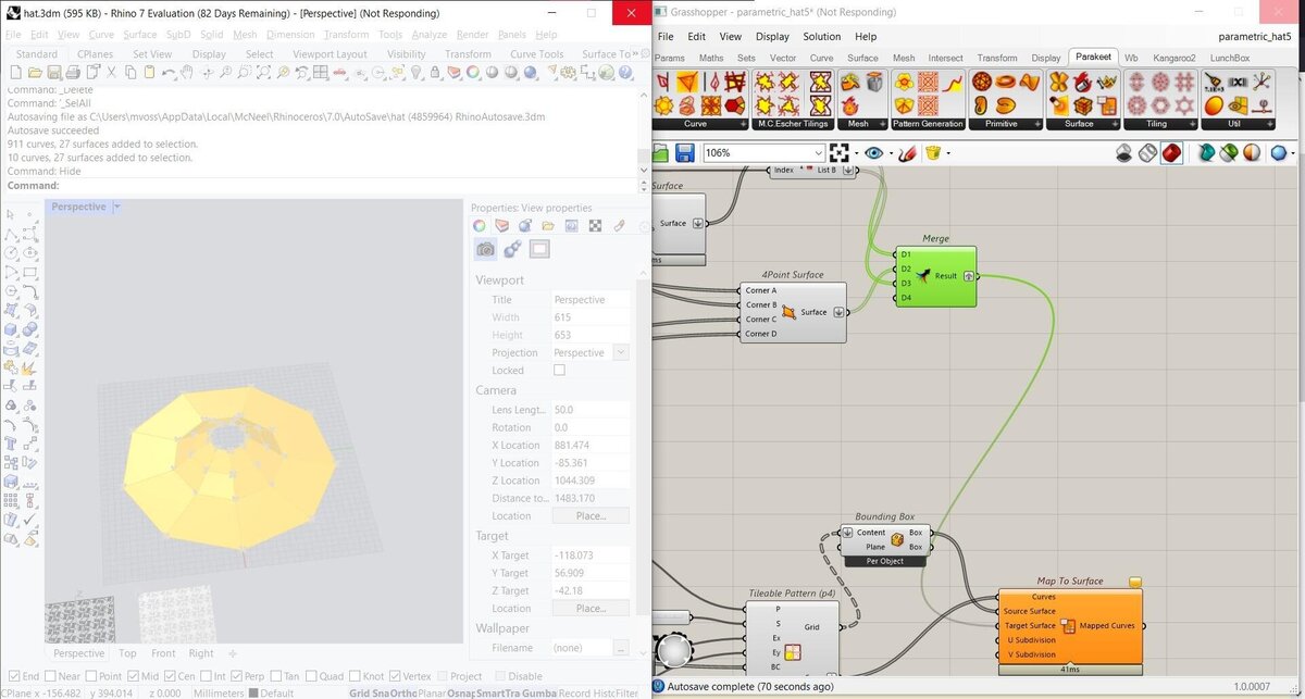
After restarting, I first tried it on one surface as to not freeze the progam again, which worked how I wanted it to!
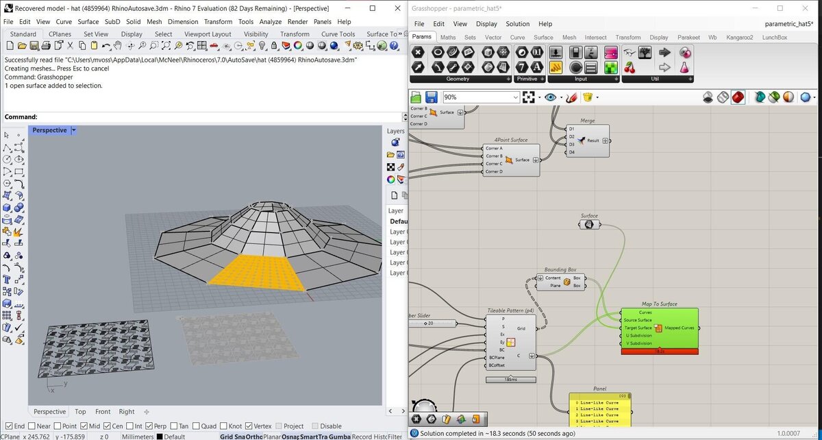
Then I tried it on a row of surfaces which also worked (finally).

I also played around with some of the pattern generation options in Parakeet. Most of them are patterns that look really cool but wouldn’t work to make the material bend; most are continuous lines so that would just break my hat into little pieces if I were to cut them. Engraving them would work but that’s not the goal of this deep dive.

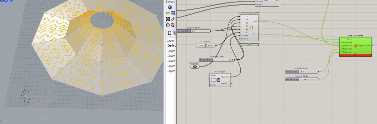
When I removed the bounding box node in between the grid output of the Tileable Pattern and the source surface input of the Map to Surface node, I got rid of some horizontal lines that I didn’t want in the pattern. I thought the bounding box was necessary but it’s not.

Here you can see the above pattern mapped to the surface of the hat. With the number sliders you can set the repetition of the tile.
Finger joints and notches
The next thing I needed to figure out, was how to make joints and notches for the joints in Grasshopper. This is very easy to do in Fusion, so I was very optimistic. It turned out to be quite a struggle.
I started out by targeting the sides of the middle row of the hat based on the points in the lists from which I made the surfaces of the hats. With a bit of List Item and Number Slider magic, I found the correct vertices to target. I created a set with the top and bottom points of the vertices and drew a line between those points.
Then I used an Offset on Surface node to offset these lines onto the surface.

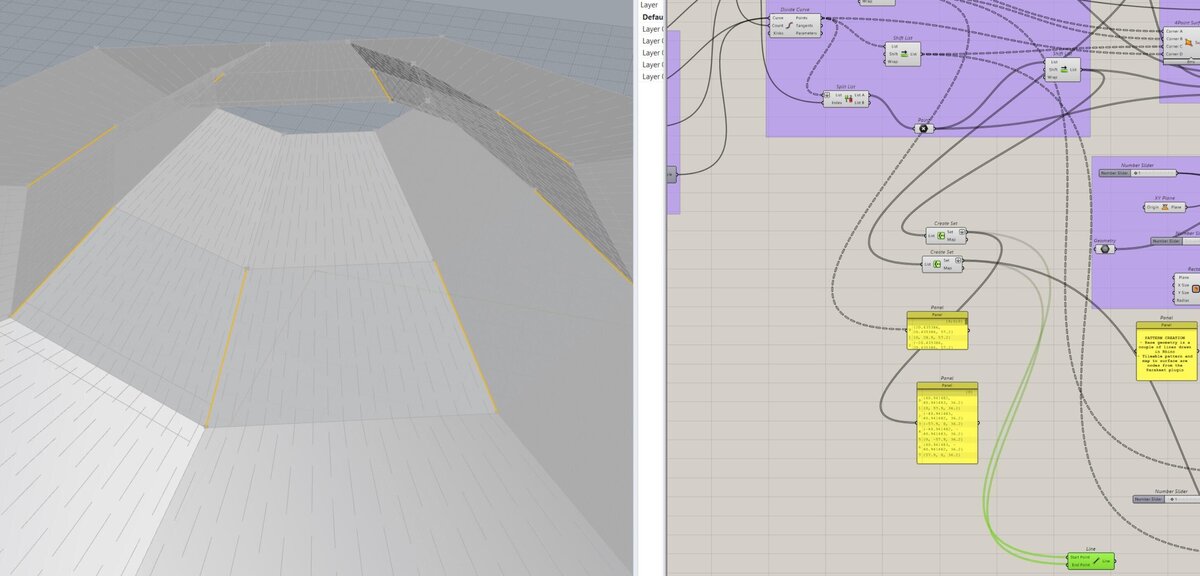
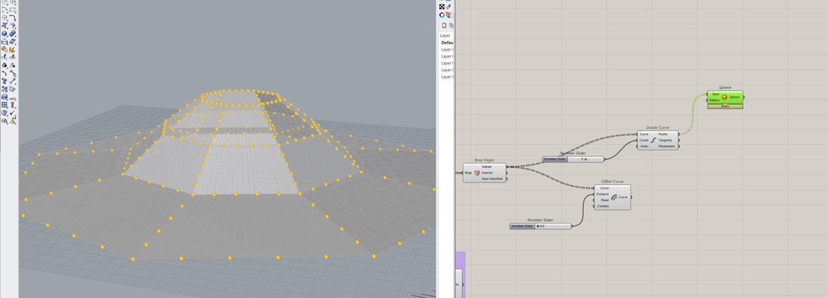
Then I didn’t really know what my next step would be, so I played around with a trick that Aslı showed me; drawing spheres on set points (made by dividing the edges of the entire hat with a number slider), so you can use them to cut out or add to the shape. I figured I could make notches or fingers like that. However round shapes aren’t great, and using cubes didn’t work how I wanted either, because I couldn’t get them to align to the hat.
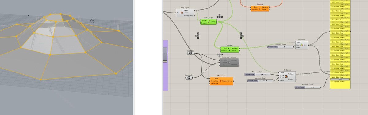
Then I tried to align a rectangle shape to the edges of the hat. The rectangle node is linked to a curve array that is hidden under the panel on the right (not a great screenshot).
Now that I’m writing this a couple of days after trying this, I know why it didn’t work: the plane input for the rectangle is set depending on the starting point of the plane, so the direction that the rectangles are following here is the direction of the bottom surfaces.
Here I tried setting the plane to the Brep edges instead, but then the orientation was all wrong.
Intermediate reflection
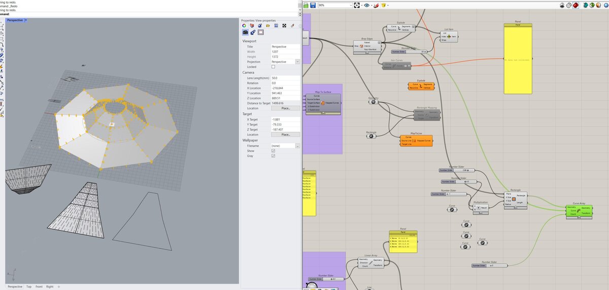
I ended up splitting the Grasshopper file into 2 parts for the time being: one to create the shape of the hat and add a pattern on it to make it flexible, and one to add finger joints to the pattern part and create a connector based on the size of the finger joint since then I would only have to deal with the X and Y axes. This means that if you want a different shape for the hat, you need to bake the shape and flatten it with UnrollSrf (seen in the bottom of the picture), and link the second part of the Grasshopper file to the flattened pattern piece. I tried many times to get the joints directly on the 3D shape in Grasshopper, but they never wanted to go in the direction I wanted them to.
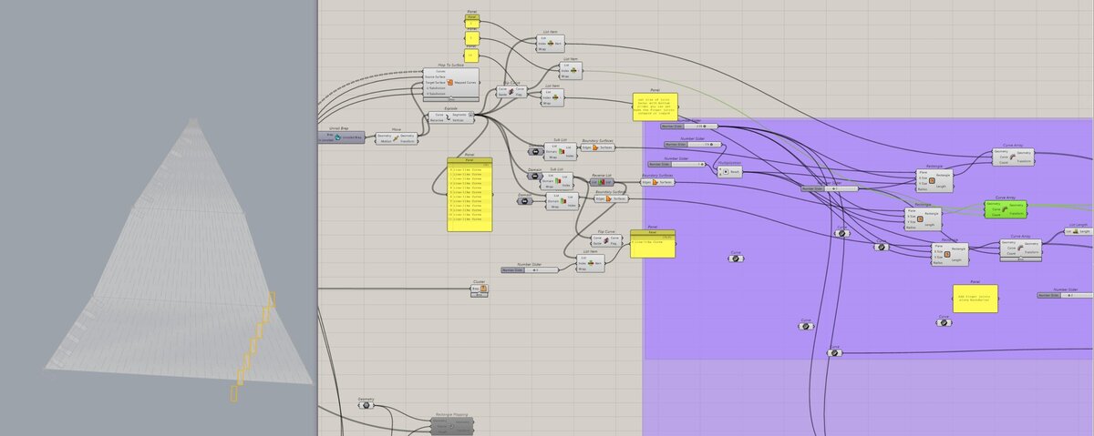
I used the same rectangle node and connected them to one curve array per panel part. This is necessary because the three rectangles all need a different plane in order to have the right angle relative to the sides of the panel. To do this I linked to the geometry in Rhino with a Curve node in Grasshopper.
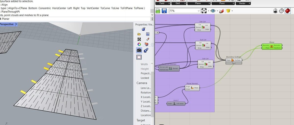
Then I mirrored the three sets of joints to the other side using a Plane Normal node with an origin defined by the Polygon Center of one of the panels (doesn’t matter which one because they’re symmetric) and a Unit X vector.

I didn’t want the first and last joint of each side, so I constructed a domain from index 1 to the last index minus 1 and created sub lists of each of the rectangle lists.
I also made a tiny connector and exported the first test as SVG.

Fusion intermezzo
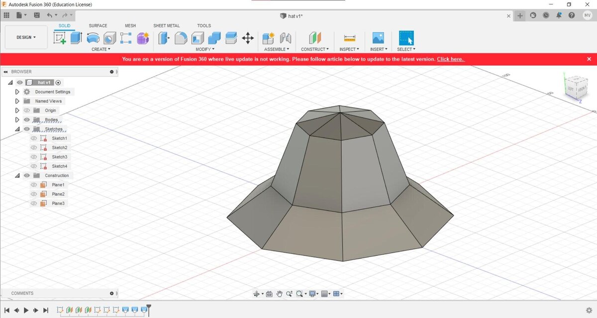
Since I wasn’t very convinced by this workflow, I decided to also give it a quick go in Fusion. Here I lofted the shape of the hat based on three planes with circles on them, similar to how I constructed the hat in Rhino.
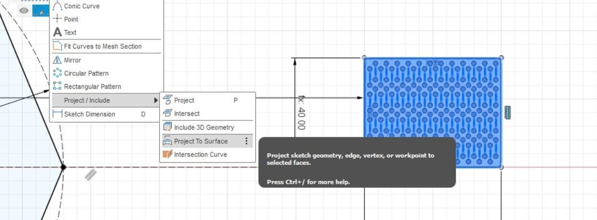
Then I tried to project a parametric rectangular array onto the surfaces of the hat, but that didn’t work how I wanted because I couldn’t select the surface. I tried in a couple of different ways, then got frustrated again and abandoned this idea.
Grouping
I decided to bring some order into my Grasshopper file, because it was getting out of hand. I grouped the different elements in the file and described what they did in panels, so it is easier to understand what is going on.
I got rid of the collections of points above, because they didn’t do anything anymore.
One of the main issues with the design I had so far, was that I would have to bake a panel and use UnrollSrf in Rhino, because Grasshopper doesn’t have a feature like that. Then I would have link the joint node collection to the geometry manually, and that didn’t sound very parametric to me.
However! I typed in unroll once more in my Grasshopper search bar, and suddenly I saw Unroll Brep. This is a Lunchbox add-on that I installed 3 years ago and didn’t realize I had now or what it was for, but stumbling upon this feature felt like a gift from above. I think I looked for it many times before (at least, I could swear that I did), but suddenly there it was.
It’s an unrolled surface! And it’s parametric and linked to the hat!
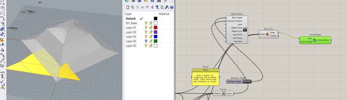
I moved it out of the way so you can actually see it.
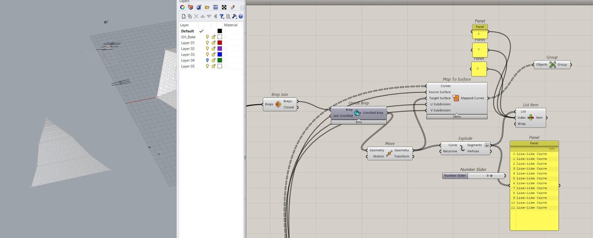
Then I linked the joint generation nodes group to the unrolled panel. I also inverted the direction of the rectangles because I figured notches would be more useful than fingers here.
Fusion intermezzo II
I was thinking how it would be best to connect my panels; I could calculate the angle of the panels, but the charm of my parametric hat is that it can take any shape, which means the panels can also take any angle. I could make many connectors for all kinds of angles (calculated of course), but I think that would be wasteful and not really in the spirit of the design. So maybe the connector should also be a living hinge, so they don’t have to depend on the angle of the specific panel. In that case I can also combine shapes more easily. It may be better to make the connector out of plywood.


I cut out the design above and a couple of variations of it, but they would all break immediately (cardboard and plywood). I made another one like below but that one also broke, so I made it even simpler in the end.

Some general notes
- Flattening data in lists can make sense of data when all hope seems lost
- List Item can also give great insights
- Don’t forget about add-ons
Rhino:
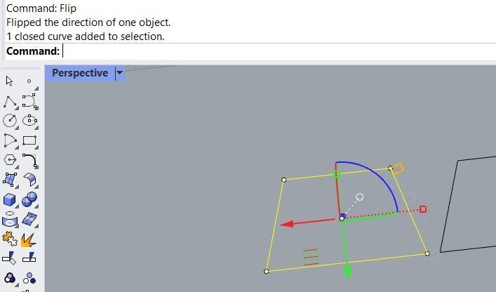
- Flip changes the orientation of a surface, so if you need something along a curve and it’s going in the opposite direction, use that
- https://www.grasshopper3d.com/forum/topics/flow-object-along-surface-command
- https://parametrichouse.com/polysurface-tween/
- Sometimes you just have to pick your battles and use a different software for a different step if the program doesn’t want to bend.
- Maybe what I should’ve done, was draw the pattern flat in 3 surfaces, then bend them to create the digital mock-up.
Reflection
I think in the end I spent about 10 hours getting it to do something simple. I wanted to start the whole thing over in Fusion at some point, but I also couldn’t get that to work either. At some point I should have taken a break and done something else, but I was in too deep with determined frustration and I didn’t want to stop until I had something that could work. In the end I got it to work, but only after leaving it to rest for two days. Sometimes rest and a clear mind can help (what a surprise). Let’s hope this is a lesson for spiral development and stopping when it’s time to stop; I should set clearer time limits for myself and try to actually implement spiral development instead of my usual deep dives. This is my goal for next week.
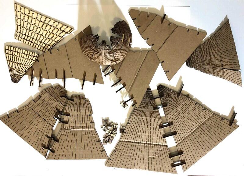
Making the hats
Now it was time to actually make the hat and hope that they work. I exported a couple of designs from Rhino (changing some of the dimensions and patterns) as DXF. I used Speed 100 and Power 80 for cardboard (2.8mm) and Speed 35 Power 80 for plywood (3mm).

These are simpler connectors.

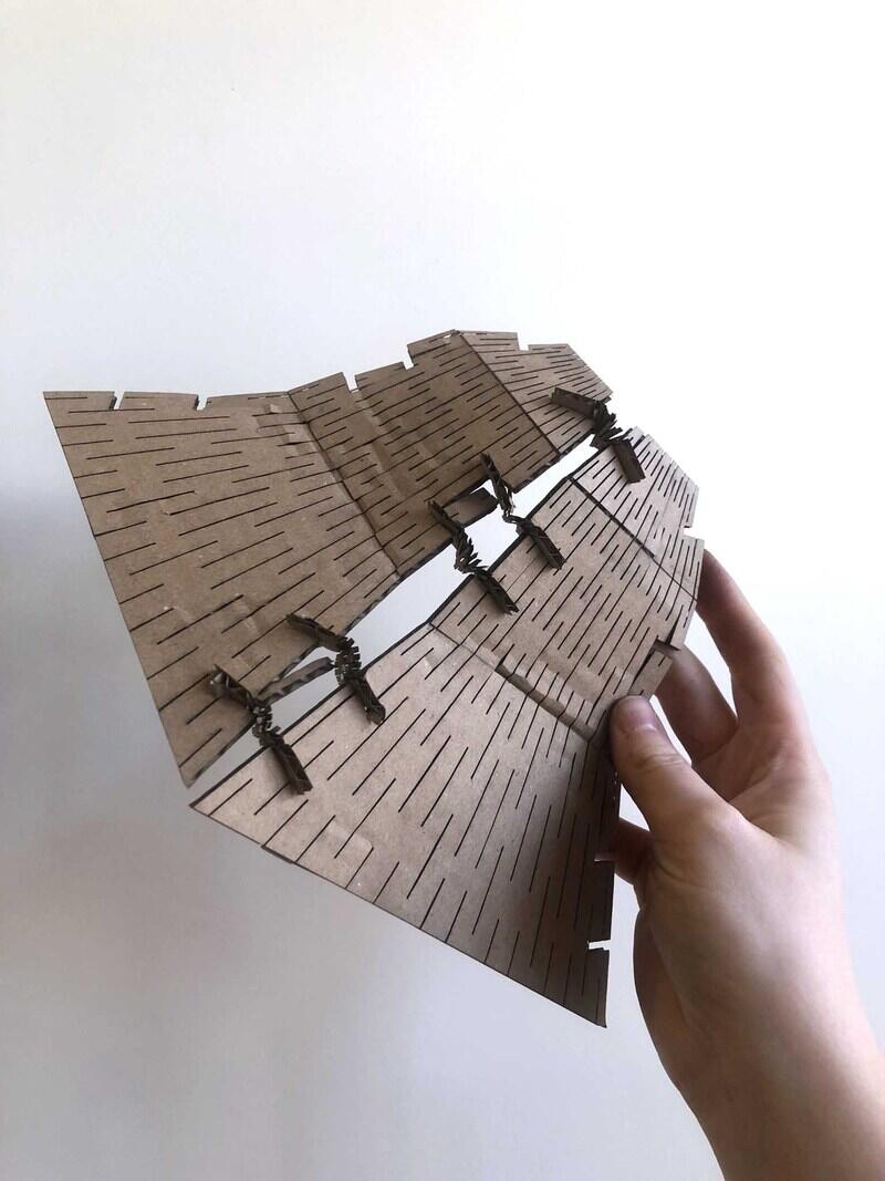
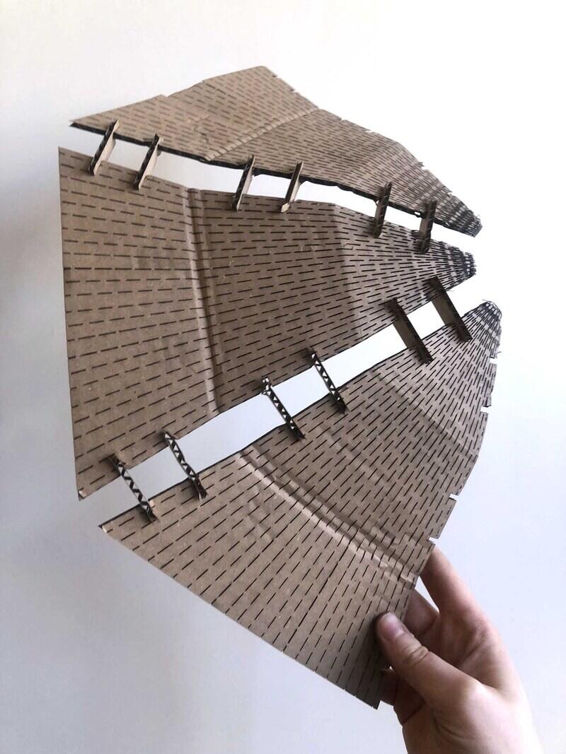
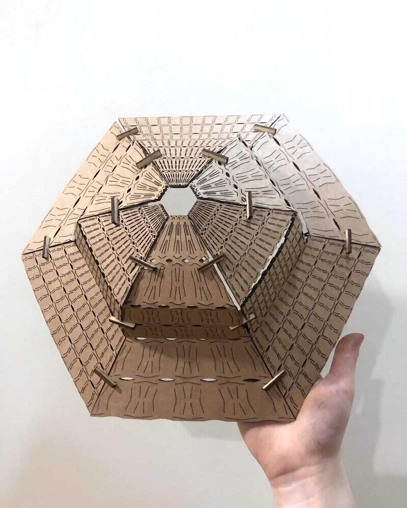
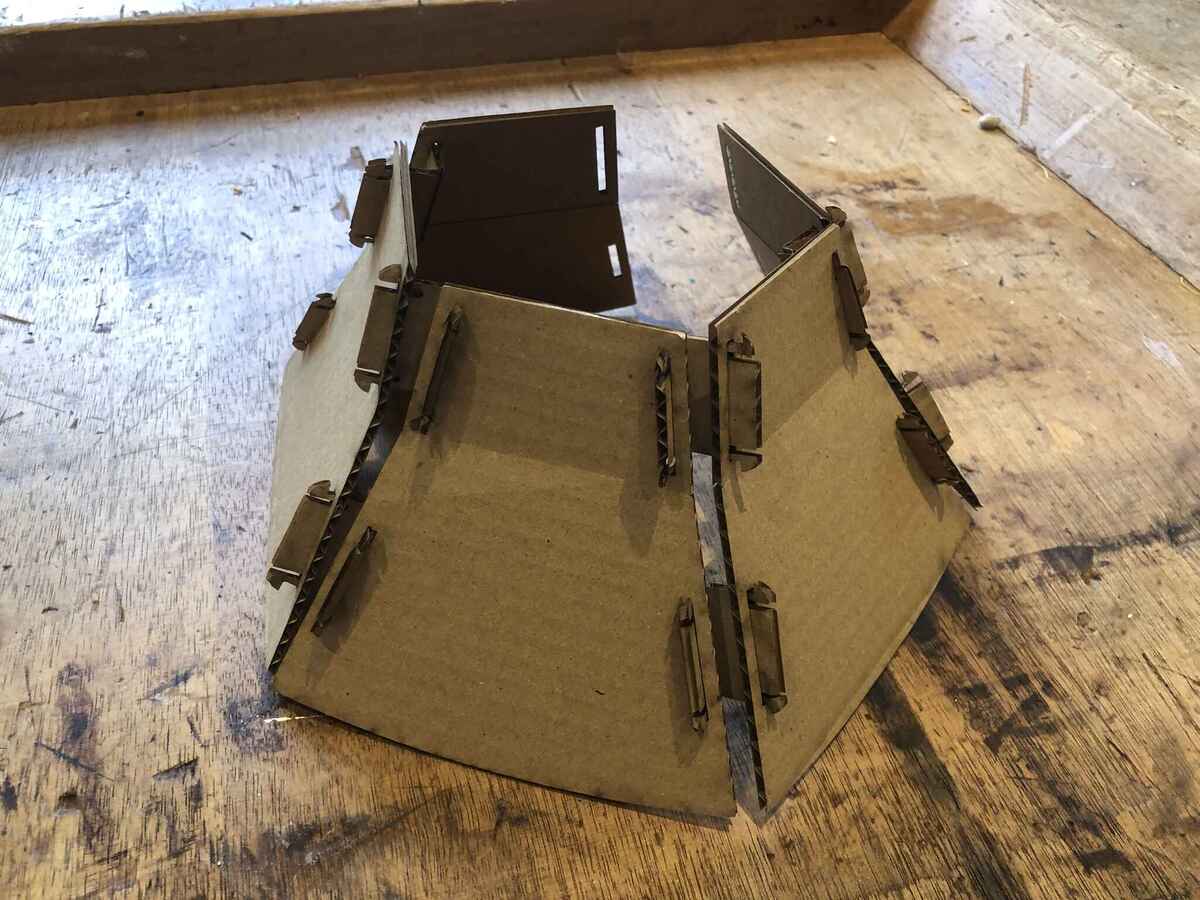
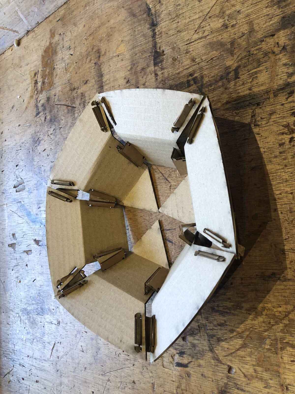
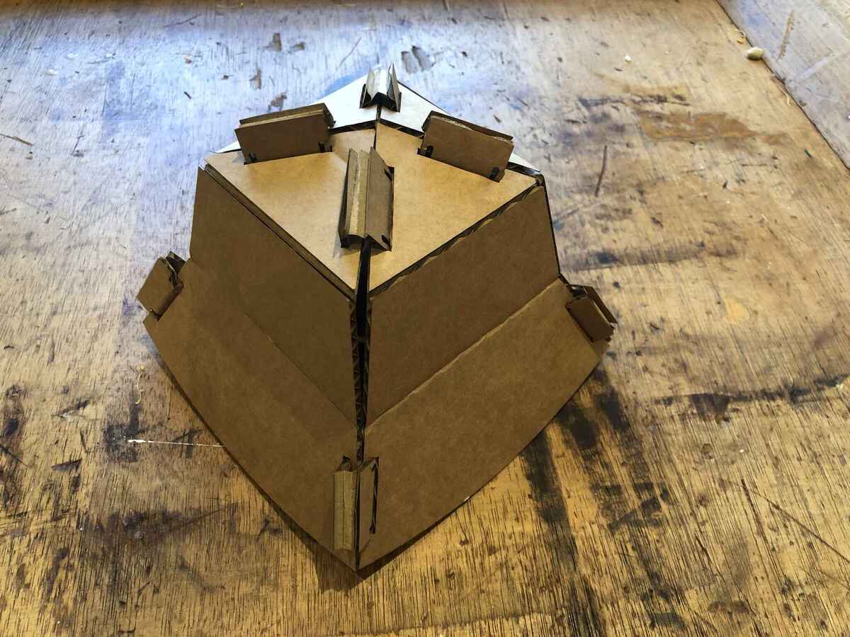
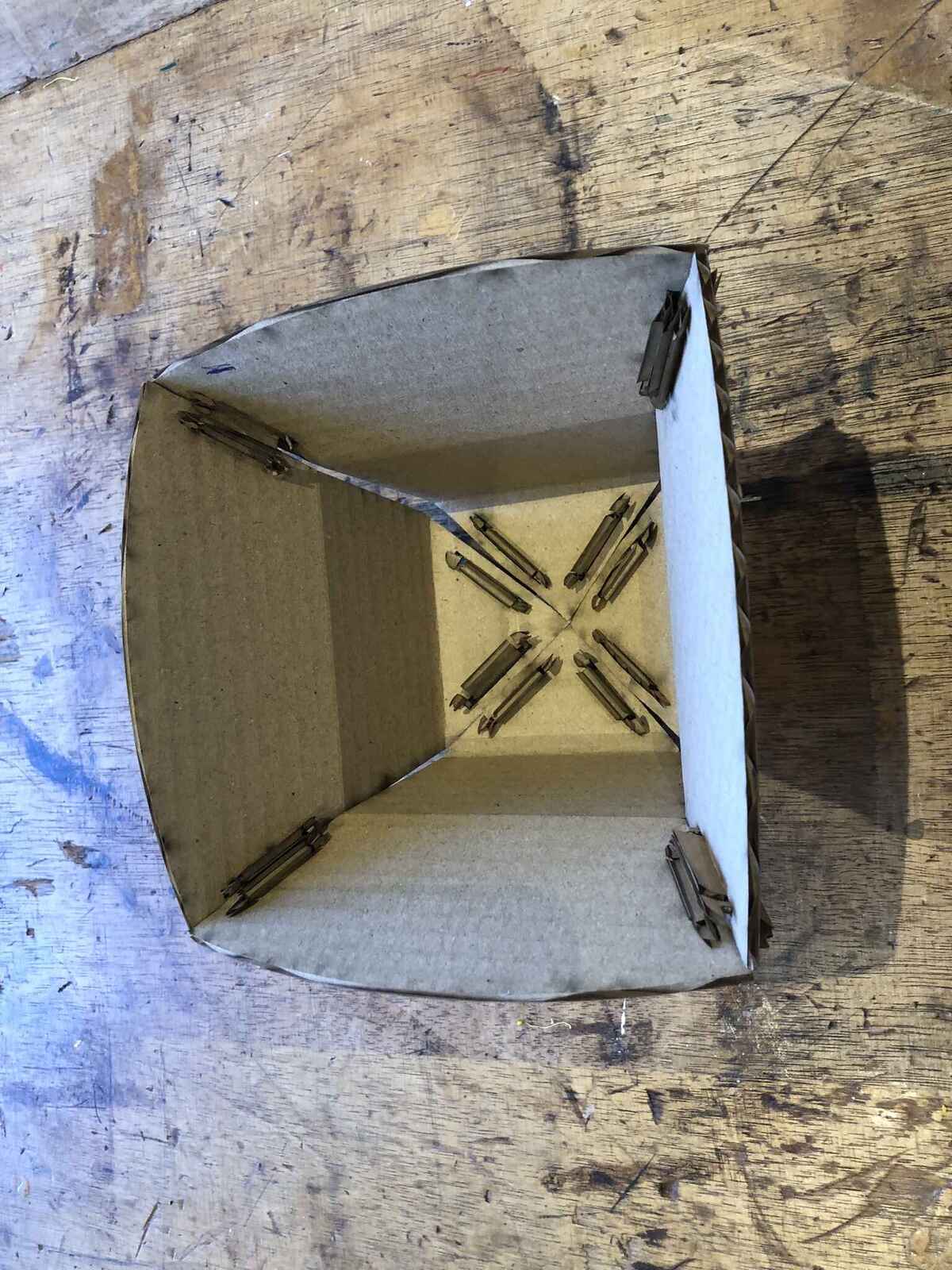
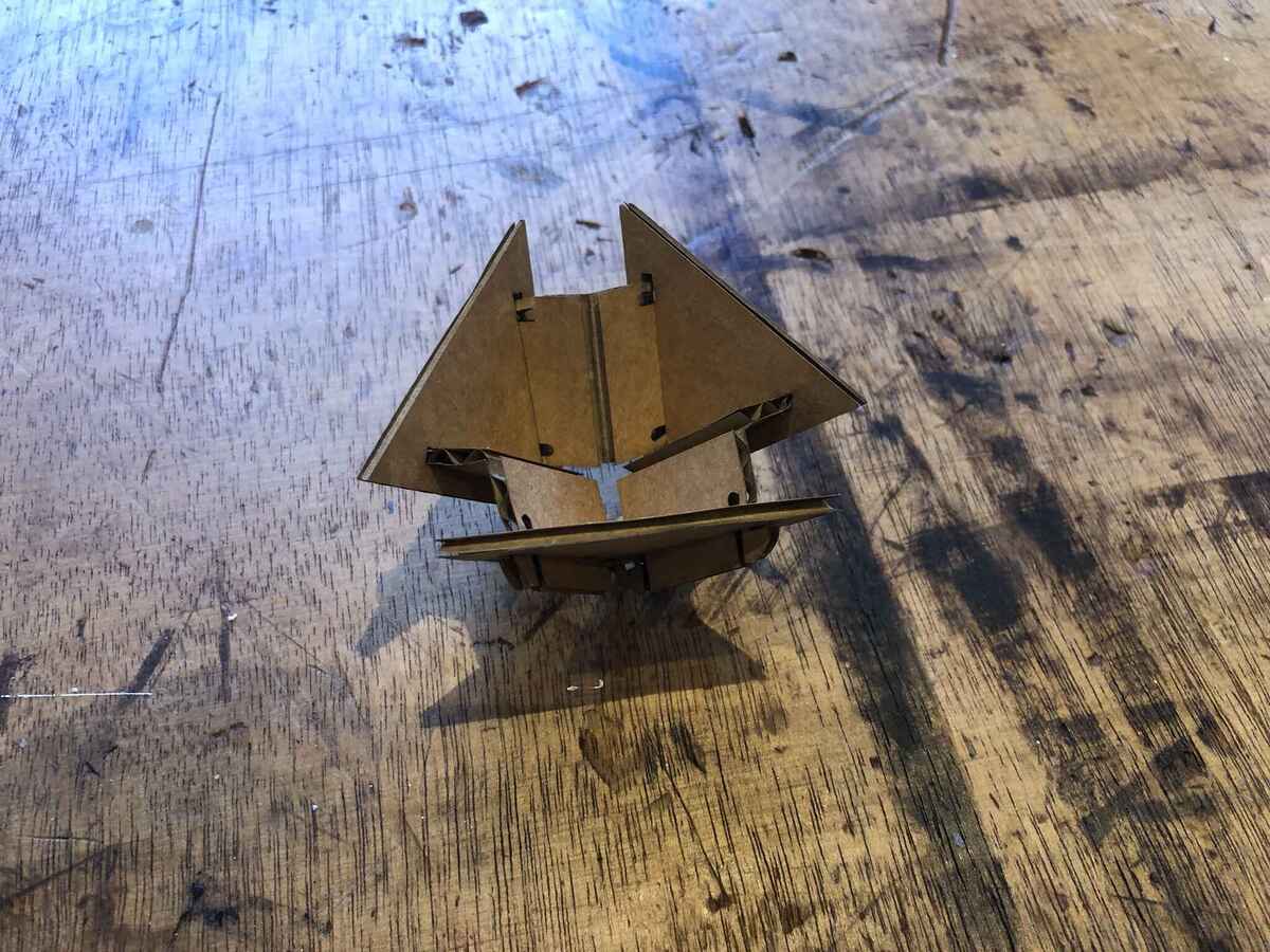
It didn’t work out with cardboard connectors because they were too small and the corrugation of the cardboard didn’t hold, making press-fit impossible. Also the panels want to flatten themselves, so they put a lot of outward tension, so these connectors slide right out once you start bending the panels. The cardboard also kind of flattens when you press it, so then the press-fit connection isn’t press-fit anymore.
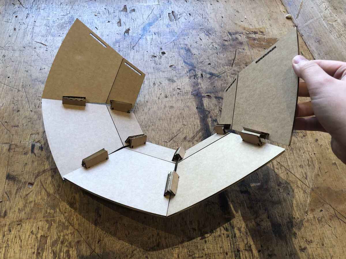
Even though the connectors are questionable, you can see the curved panels of the hat taking shape.
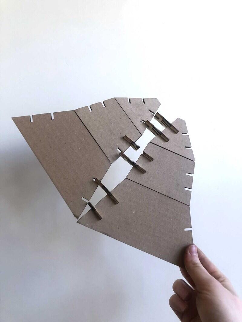
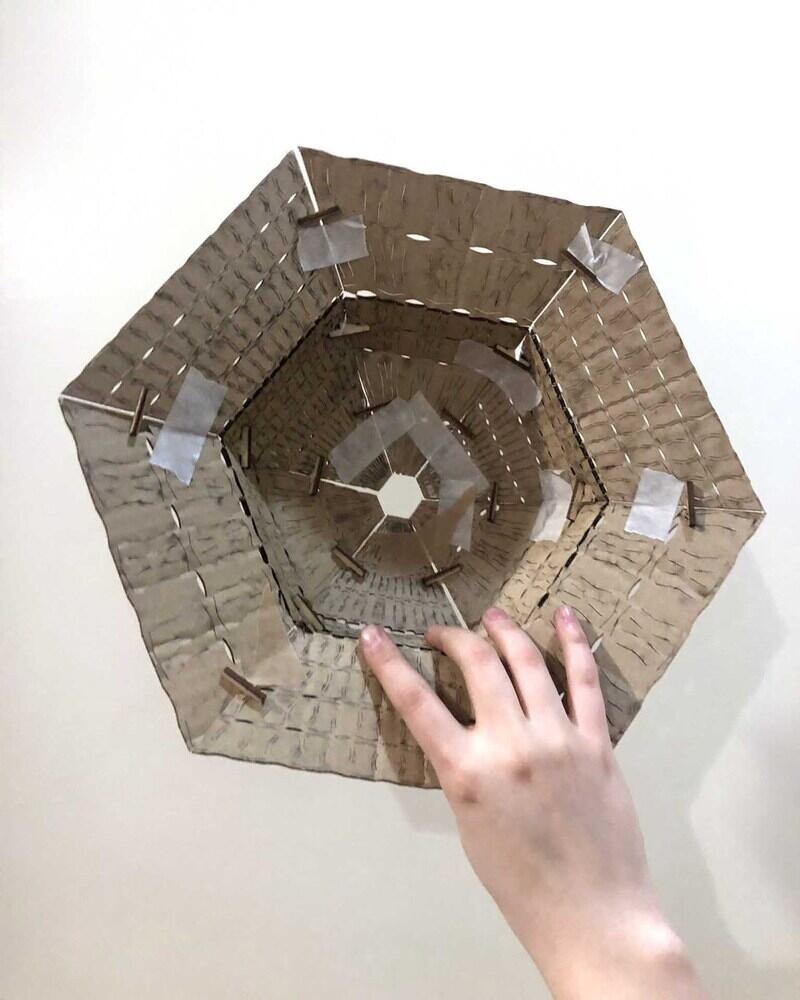
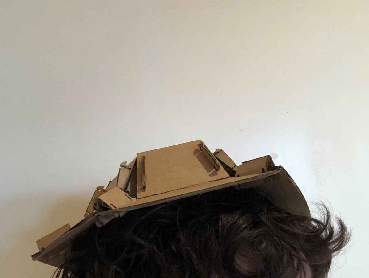
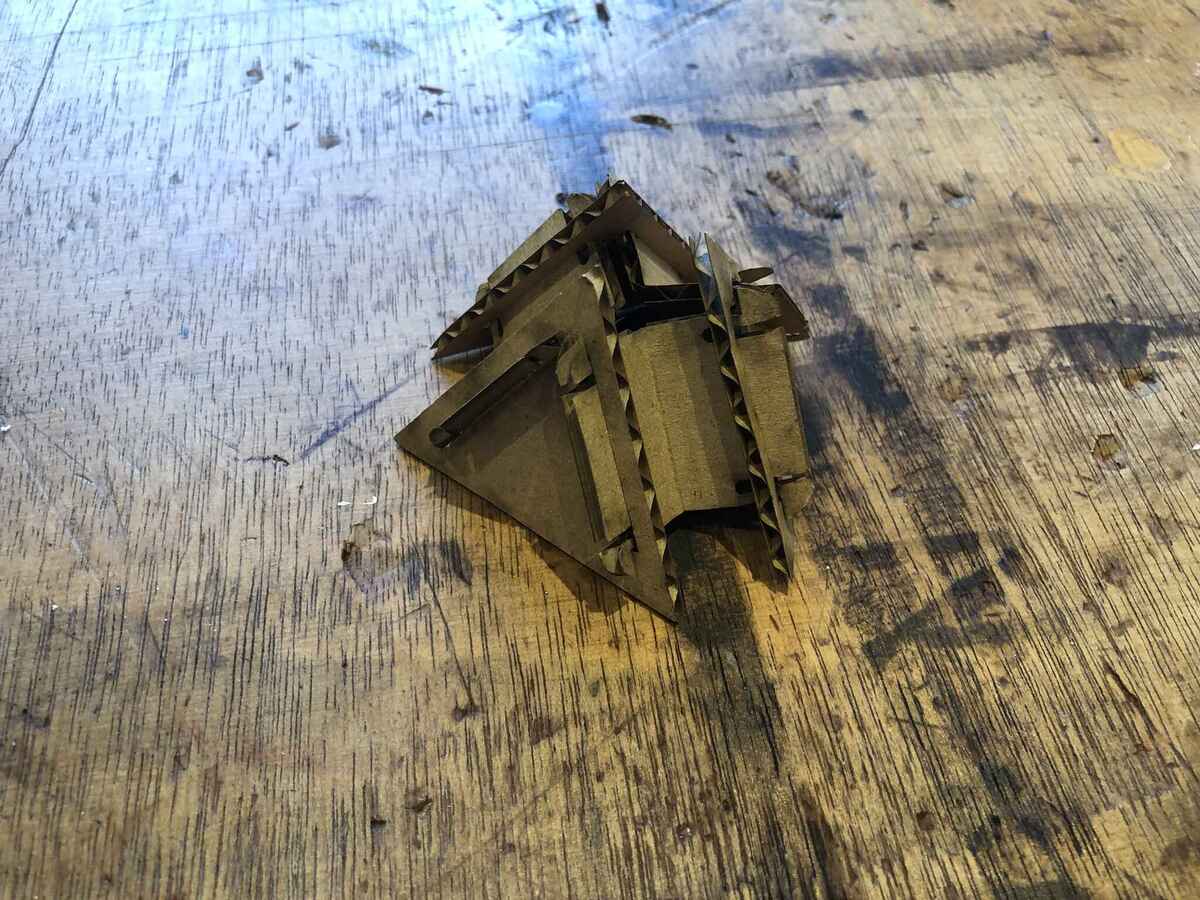
These are tape-fit instead of press-fit.


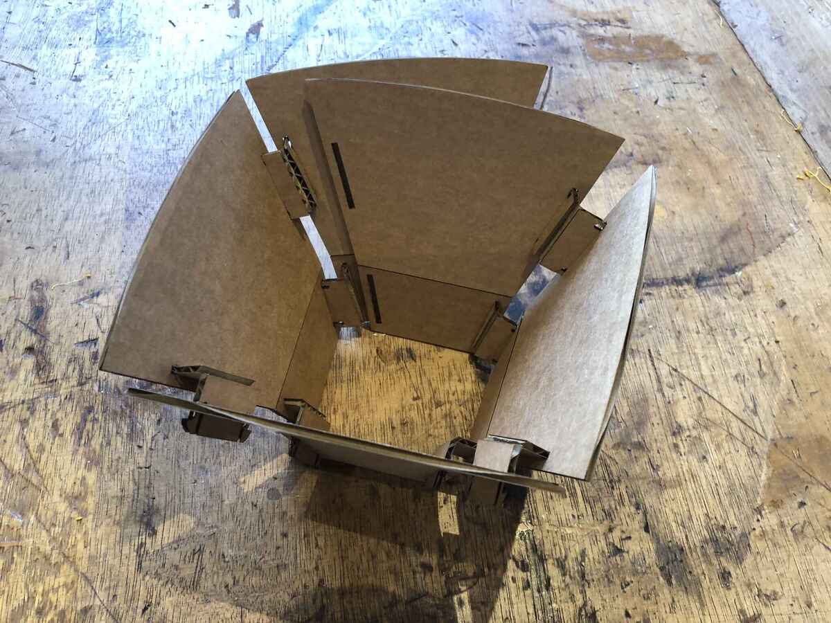
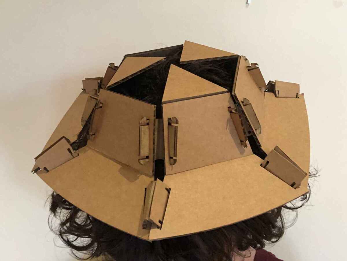
These simpler shapes are press-fit. I figured out that I didn’t need two connectors per panel so I changed that.


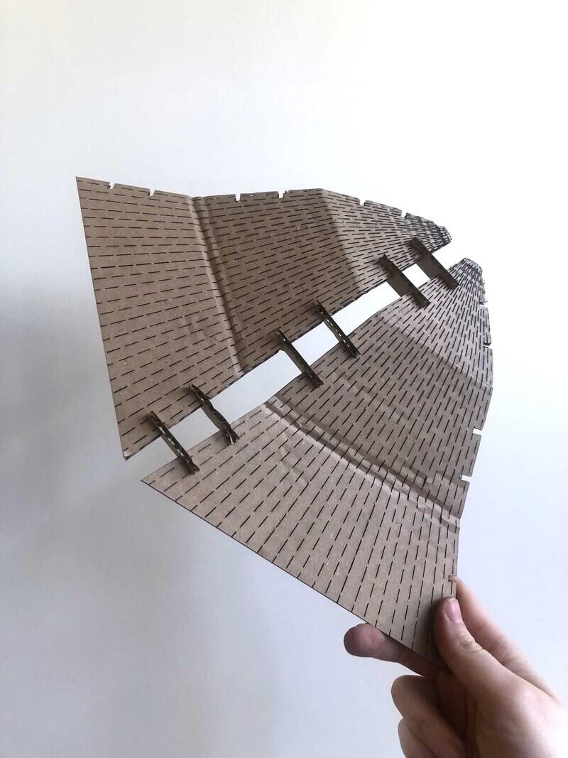
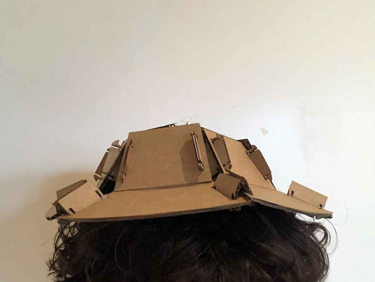
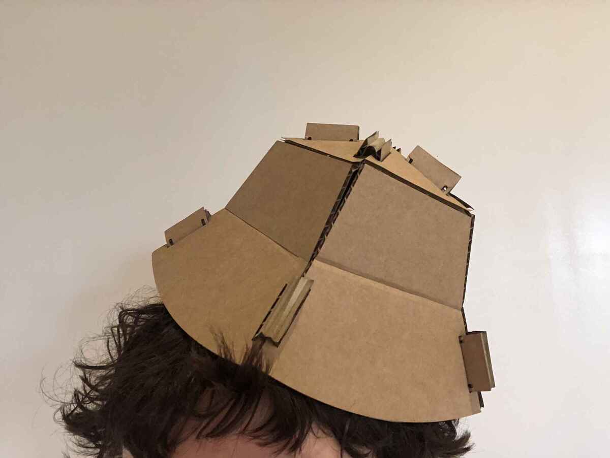
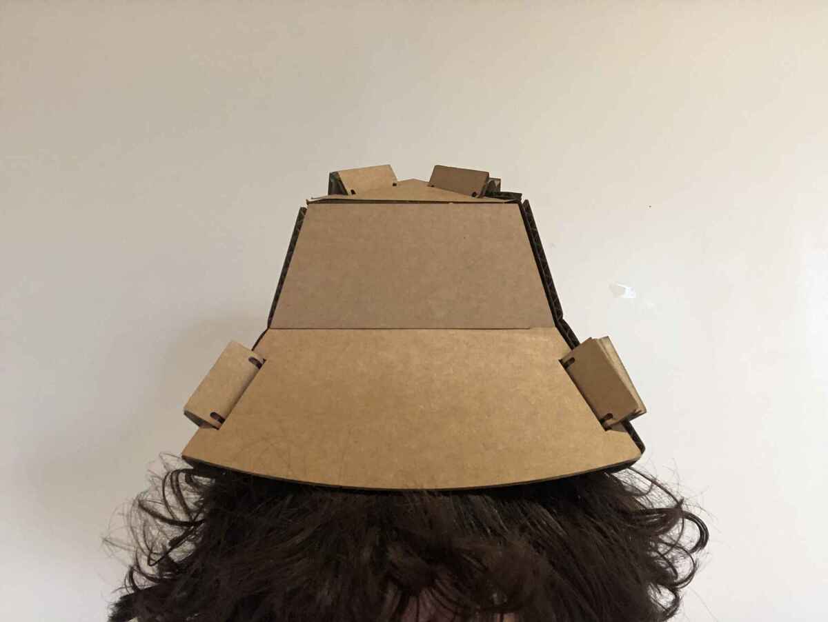
I’m really happy with this hat, but I need tape to keep the panels in place, so again not press-fit.
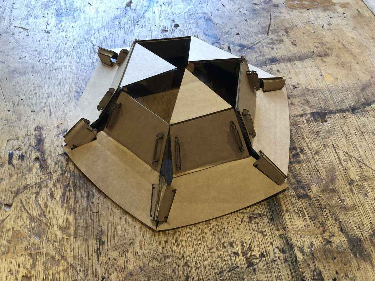
I cut some of the folding lines on the panels of the hat to see if they would be press-fit, and they were, so now they are necklaces. So now I have two cardboard looks.

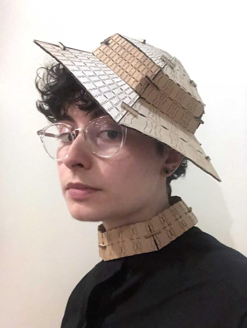
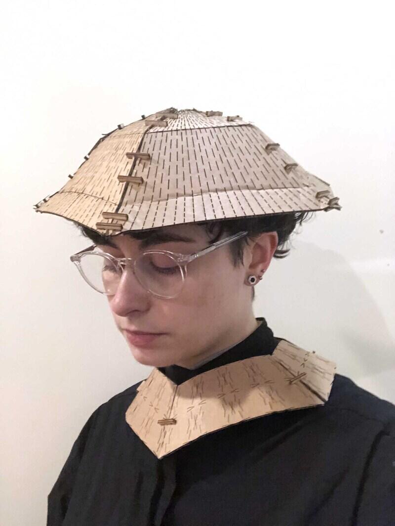
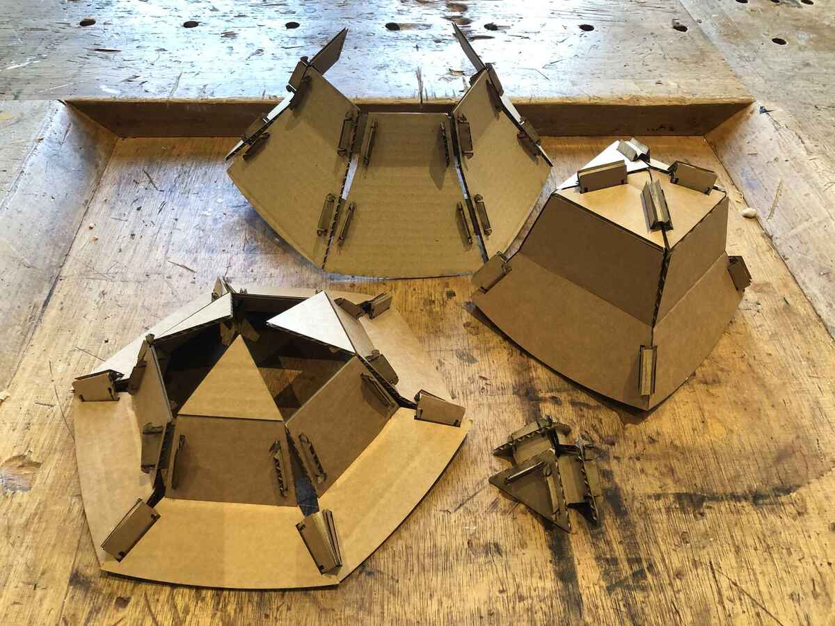
Here is the collection of tape-fit and press-fit hats and accessories. The three shapes with one row are the panels of one hat cut on the folding lines, and they are press-fit.

Reflection
I worked in Rhino and Grasshopper for about 15 hours on Friday and I can tell you that it really doesn’t feel great. I managed to have something finished on saturday afternoon, but I don’t think it’s good, so I tried to make it again in Fusion. Things that are very easy to do in Fusion seem very cumbersome in Grasshopper. At some point I had to stop and accept that for now my knowledge of Grasshopper wasn’t there yet, before I spent another 5 hours trying to make something work without understanding what I was doing. Working with lists was very confusing, and I didn’t enjoy it until the end once I got the hang of it.
I realized on Tuesday after a lot of tries that bending and folding the panels in multiple directions isn’t really possible while also making it press-fit. My original plan to tackle the requirement of assembling it in multiple ways was to be able to make different hat shapes by not bending but connecting the hats (so you could add a different brim and change the angle), but I changed that plan because I liked the idea of bending the panels. I also wanted to add interchangeable decoration to the hats, but I didn’t have time for that. Then I ran out of time to also add horizontal notches and come up with a solution for those connections, because I only had Tuesday to make everything. It would maybe also have been easier if I used chamfered slots instead of the simple rectangular slots I had now.
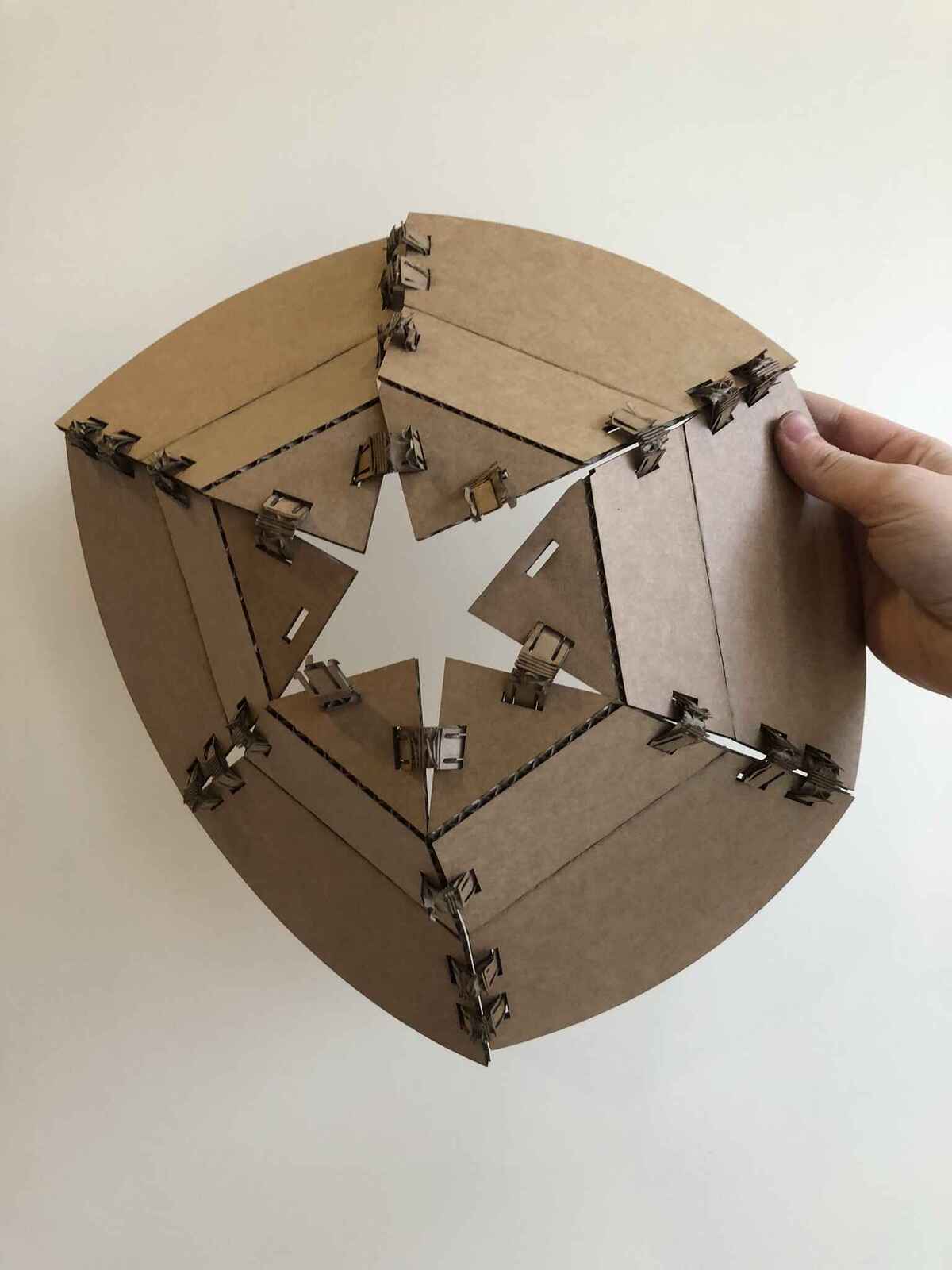
So: to be continued. I have to make a couple of simpler shapes like this to actually meet the assignment criteria. Sylvain’s basket for this week shows how to use only a couple of simple flexible and rigid parts that can be assembled in many different ways. I think this technique may be a better idea to explore.
Second attempt
It took a couple of weeks before I continued with this assignment, but at some point I had to go back to the drawing table. At first I wanted to do something completely new, but I decided against that since it was kind of unnecessary and I had to focus all of my energy on final project development. I decided to design a connector based on Sylvain’s basket as mentioned above. I tried to do it in Rhino and Grasshopper, but at some point I decided to start over in Fusion since it felt like trying to mold software that isn’t very well suited for what I want to achieve, and it cost too much time. Since I’ve used Fusion often and I’m not using techniques I haven’t used before, I’m not going into too much detail about the design process.
Fusion360
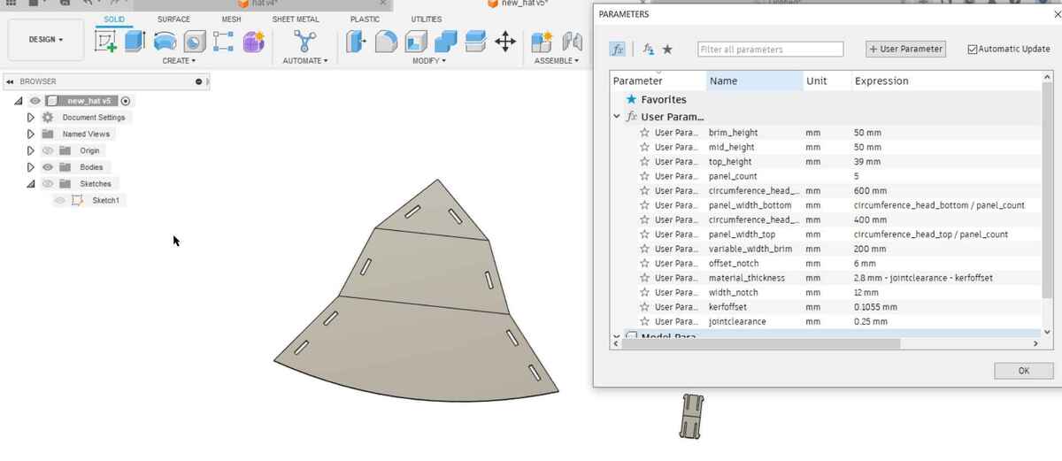
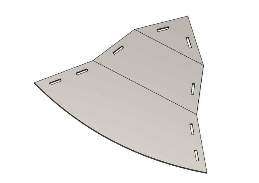
I set some parameters based on some quick measurements and sketched the outline of a panel of a hat. This time I worked directly in 2D.

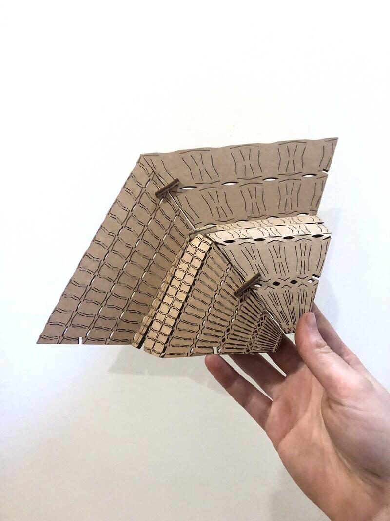
I also added slots for connectors, and rounded the bottom of the hat. I extruded the three panels separately, so I could easily export the panels with a fold line in between them later. I want to cut the fold lines lightly so I can create a sharp fold. Here you can see all parameters used; taking kerf offset and joint clearance of the cardboard into account.
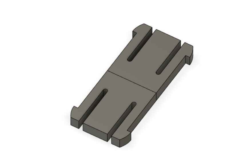
I drew a connector piece with fold line in the middle, so it can make the necessary bend to connect two panels. The hole design revolves around folding and bending, so a bendable connector makes sense.
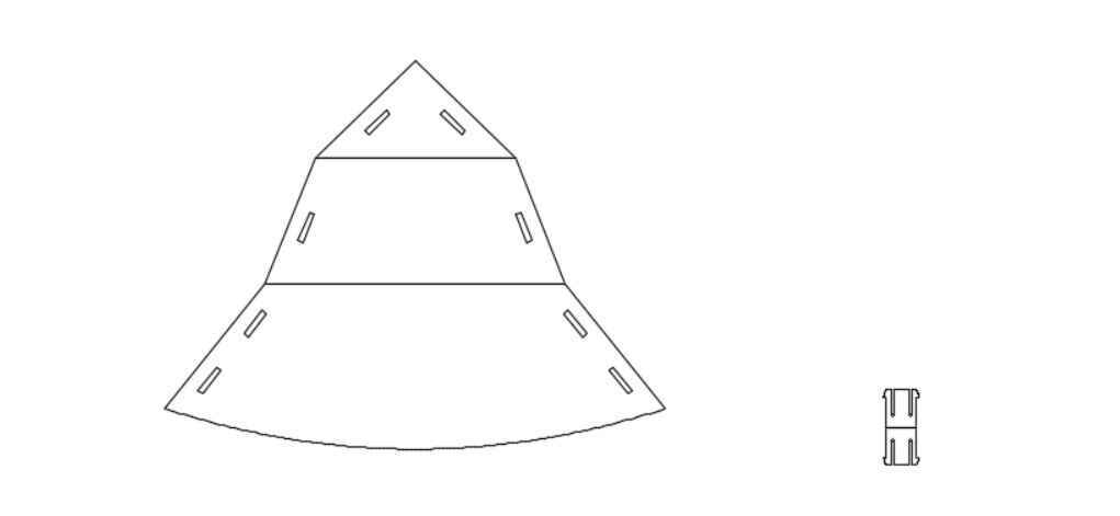
Here the Fusion drawing from the two parts created.
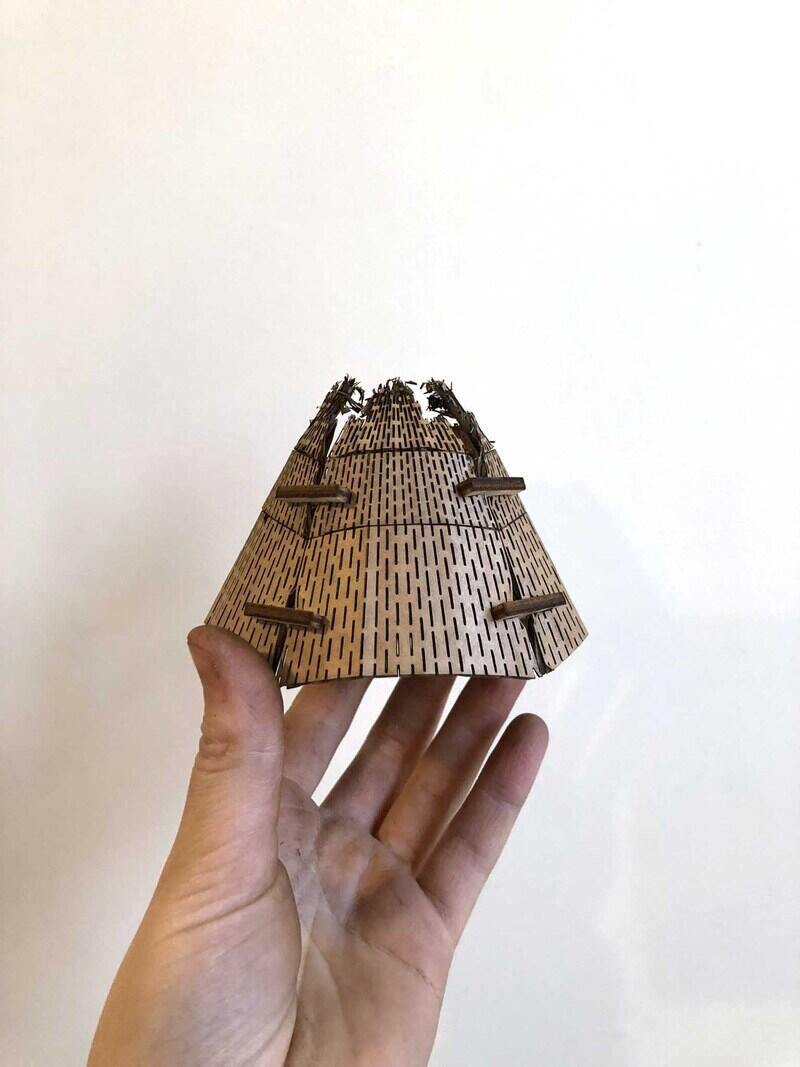
For the first try of the new design I made the connector with more engraved lines, in hopes of creating a flexure. The problem is that it’s just not possible with the corrugation of the cardboard. Half of the lines that are places with one mm in between are just flying away, since the corrugation can’t hold onto them. This makes them very weak. They’re too small and don’t work in cardboard. I also tried it in plywood but that didn’t bend enough (it just snapped in half).

The curve of the brim of the hat is also too much, and since this design is pointy at the top it can’t close properly. I didn’t take into account that since the angles between the top, middle and bottom part are variable, the parts at the top don’t necessarily align. Since the Grasshopper design was made directly into 3D in a very different way, it wasn’t an issue there.
I decided to make the connector twice as wide. That way I would only need one connector per panel instead of two. I also made the top part of the hat optional, so I wouldn’t have to start over again with the design. Having only the two bottom parts of the panels bent and connected is enough for the assignment.

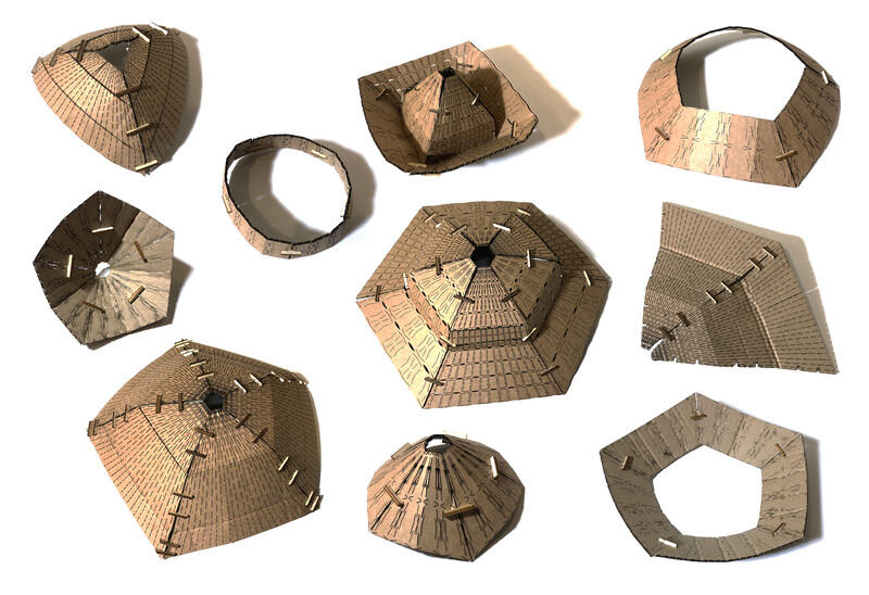
Results
The new designs form a collection of wearables. There is this neckpiece:
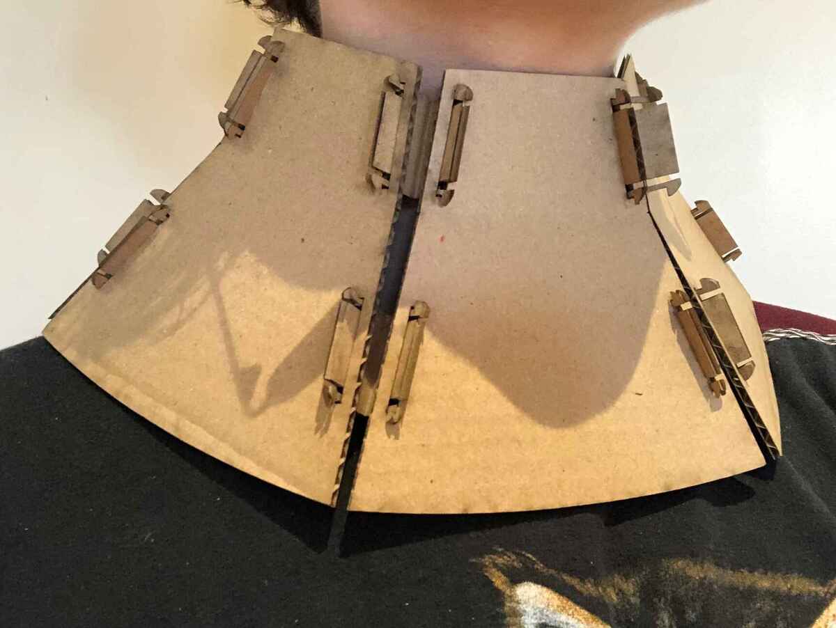
It can be made wider by adding more panels.
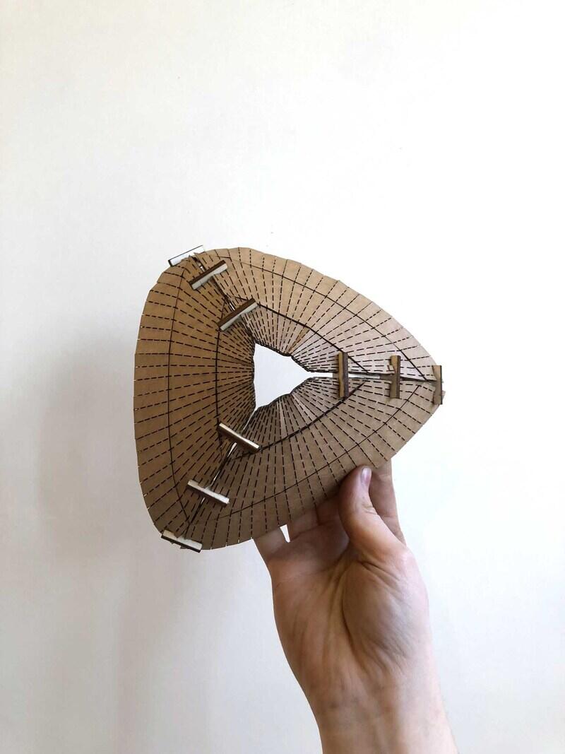
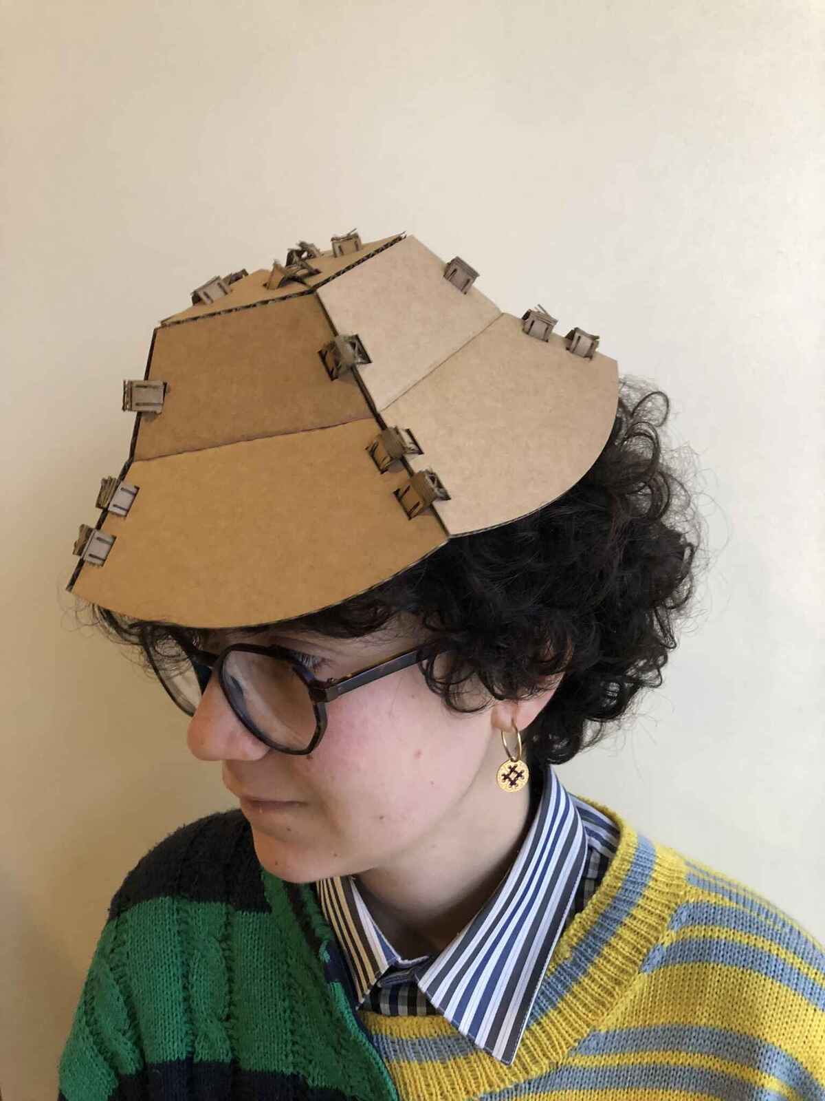
I solved the issue with the pointy top of the hat by alternating panels with and without a pointy third part. By folding them in the correct direction you can create a suggestion of a closed hat. I played around with the orientation of the connectors (also showing that that it can be assembled in multiple ways, the other requirement for this assignment). Attaching them from the inside is the ‘right’ way.
This four panel hat does have a top that connects well, since the angle was easy to determine there (90 degrees). In the middle part I left out the connector and connector slot, since the hat is already kept in shape by the top and bottom connectors.
It’s a bit small so it looks more like a fascinator.
This is a mini element (a brooch?) consisting of the top parts cut off from the first hat.
Here they are all together:
Reflection
I’m happy I finally have something I can call press-fit, but I really made it too complicated for myself. The corrugation of the cardboard made it hard to attach the connectors without flattening them by accident. The whole premise is based on folding and bending, something that this type of cardboard doesn’t like very much apparently. Other than that I tried to keep it simple and stick to the assignment this time.
Vinyl cutting
The main vinyl cutter in the lab is a Roland GX-24 Desktop Vinyl Cutter. You can operate it with mods from Chrome or Chromium, the only browsers that can communicate straight to USB which is how we talk to the plotter. You need a bridge between the software running in the browser and the machine and for this we use servers (see the terminal).
You can work with SVGs, PNGs and (since last month) HPGL. From experience I can tell you that PNG is pretty shit, SVG is okay, and HPGL is the gift that we’ve been waiting for. PNG is bad because you can’t get nice smooth lines. SVG is okay because mods rasterizes a perfectly fine vector file to then vectorize it again (but worse). HPGL skips all of the nonsense and works straight from the vector file. This is also great for pen plotting, because before that wasn’t really possible with the Roland because it would only work with filled shapes, so you couldn’t make something with overlapping lines (like spirographs).
How to use
You start by loading your material. Use the handle in the back to lift the gripping wheels. Handle in horizontal position means it’s loose; vertical means it’s tightened.
- Wheels can only be positioned in the light grey areas
- Move them from the back
- First one has to be on the left side in the big light grey area
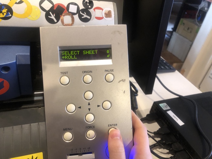
- You can select roll, piece or edge. Use roll when your material is on a roll, or piece when you’re working with a smaller piece. We don’t work with edge (not sure what it is)
The only things you should be doing in the machine menu are:
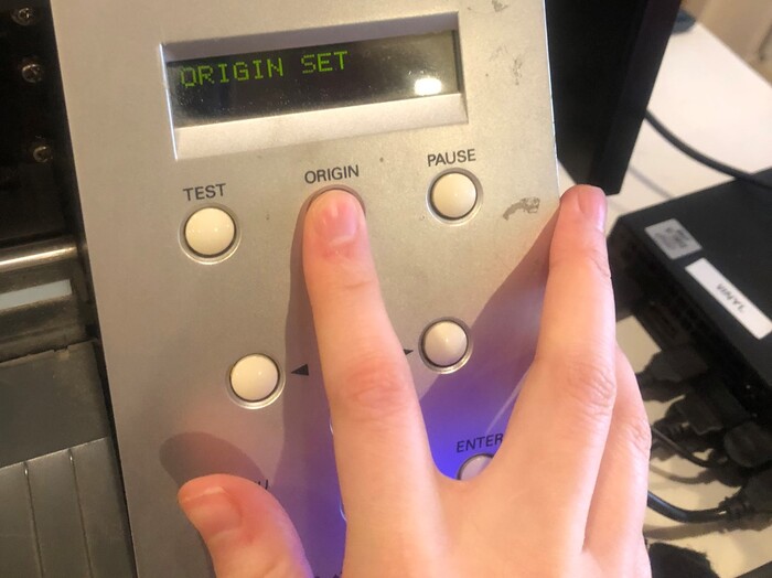
- Setting the origin (hold the button for a second)
- Moving to the origin
- Loading material Other than that, only operate it using mods, so don’t change settings in the machine menu.
Mods
- Start up the computer and boot in Ubuntu
- Open the terminal
- Type
cd modsfollowed bybash mods - Chromium opens mods; right click and go to programs > roland gx/gs > cut
- Load your file
- SVG: set dpi or unit according to your file; double check dimensions
- PNG: idem
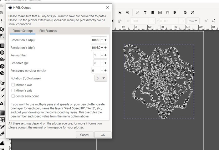
- HPGL: when exporting from Inkscape the standard is 1016DPI so if you didn’t change it, set DPI to that
- If you want any other size, you can play around with the DPI or units until you get the dimensions you want
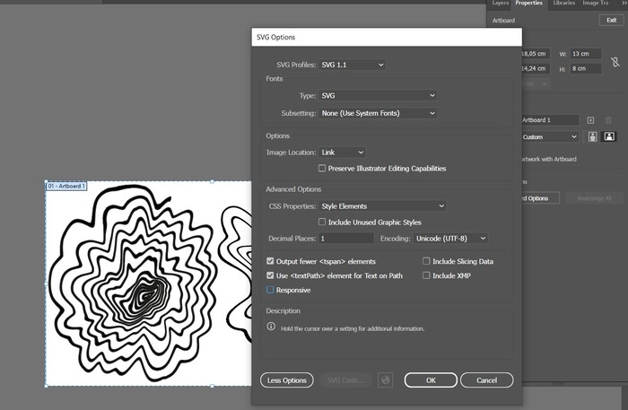
- If you’ve exported an SVG from Illustrator, make sure you uncheck ‘Responsive’ because otherwise mods will not read the height and width of your file and it won’t load as a result. Also keep in mind that when you work with artboards, mods will see the size of the artboard as the dimensions of your file so don’t leave a lot of whitespace around your file
- Don’t change tool diameter if you didn’t change the tool (so basically never because we only have 45 degrees ones)
- It’s not a driven knife, it drags according to the line
- Do a test cut to see if it cuts through the material and change force if needed
- Calculate
- Send file to machine from websocket device; websocket print should be off


Assignment
For the sticker assignment, I’m going to make a messy spiral, as a reminder to work with spiral development, because I clearly need it this week. Instead, I plowed through with one thing, ignoring everything else.
I started by drawing a spiral, took a photo of it and opened it in Photoshop to clean up the photo and to use the Liquify filter to warp it.
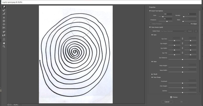

Then I saved it & opened it in Illustrator to use Image Trace > silhouettes to get a vectorized image.

I also made another spiral because I thought the first one looked too much like a flower.

Then I exported them together as SVG. Later I realized that was inconvenient, so I exported them separately too.
Then I realized my lines were really too close together for the size I wanted to make them in; I also lost some details in the rastering process in mods, resulting in my spirals having some gaps. I decided to convert them to HPGL to work around this.

DPI is set to 1016 by default, so if your size is exact, it should be that number in mods.
In the end I didn’t use the flower shaped spiral, because the lines were too thin; I made a third spiral by cutting out the inside part of the second spiral and making it bigger. That one worked out pretty okay. The second spiral was still too small in scale, so it resulted in lines being as thin as a hair which you can’t really weed.

Weeding
I did cut tests for stickers and thermovinyl; for stickers I used a force of 80 and for thermovinyl I used 120. The stickers cut through very well, but the thermovinyl not at all, so that was a shame because I found out at home.
The weeding part was fun; I used a pin to take off the material I didn’t need, then I covered the stickers in masking tape and carefully took them off their backing material.

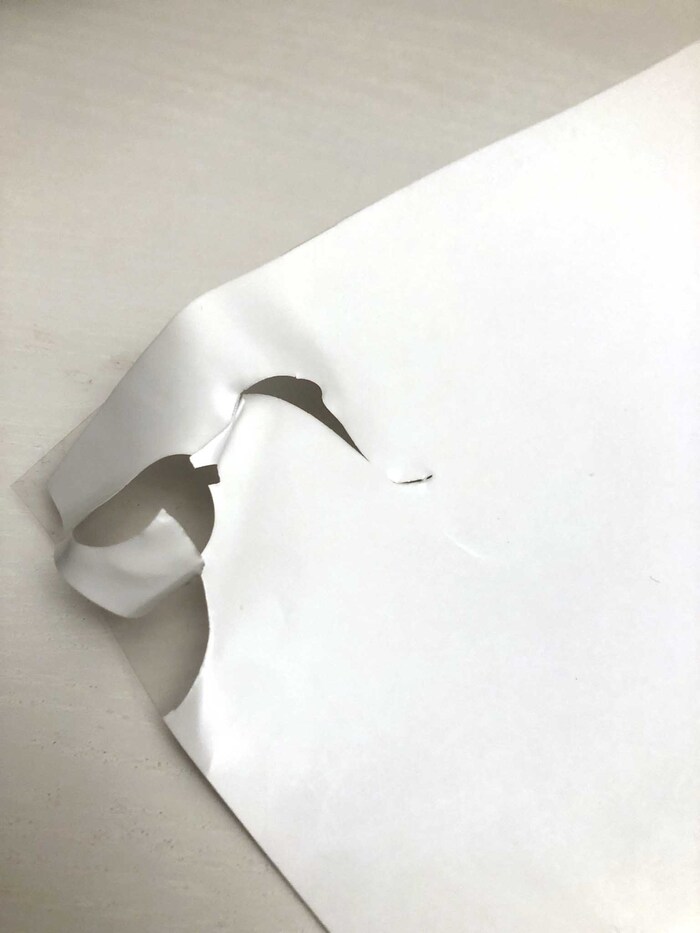
Then I stuck them onto handmade paper from a couple of weeks back. This paper really doesn’t work very well as a base to stick anything to, but I really like the way the sharp sticker contrasts with the irregular paper on the left. The paper on the right is made of cotton fibers, which gives it a very soft look. In this case I think the scale of the sticker doesn’t look right.


Conclusion
It was mostly because I wanted to use scraps so I wouldn’t waste material, but because of that I had to scale down more than was possible. However, I ended up really liking the spiral with the really thin lines and some of the lines missing, because it gave the spiral a more 3D effect.
I did notice that the lines of the stickers were pretty rough, even when using HPGL; I thought it was the blade at first but after opening my HPGL file again I noticed that the lines turned really jagged. I think there is some kind of export issue between my illustrator or Inkscape paths and HPGL, because my SVG vectors were fine; something to look into.

Files
- Fusion360 STEP files for the hat and connectors
- Fusion360 STEP file for the new press-fit hat
- Rhino and Grasshopper file (open Rhino file, then open Grasshopper file)
- Spiral SVGs
- Joint clearance comb
Lecture notes
Knife cutters and laser cutters
- Wondercutter: handheld ultrasonic cutter
- Fiber laser cutting can cut through metal, CO2 laser cutting cannot cut through metal (our BRM laser cutter is a CO2 laser) & diode laser cutting which is the newest & most expensive
- Daniele’s Fabulaser: open design that is affordable but with specs from the expensive laser cutters
CAD
Computer aided designing
- Parametric Blender extension
- FreeCAD nodes workbench
- Open source nesting software: Deepnest
- Mods: open source modules to control all kinds of machines with (maintained by Fran)
CAM
Taking your CAD design and turning it into something the machine understands (computer aided machining)
Vinyl cutting
You can make:
- Masks for screenprinting or sandblasting
- Electronics with copper tape
- Foldable objects
- Stickers & heat transferable stickers
- Origami simulator (kirigami is with cuts)
- Weeding: process of getting rid of the material you don’t want
Laser cutting
- Cutting with vectors
- Engraving with raster or vector
- Online halftone maker
- Neils joints reference:

- Chamfers help you aligning
- Flexures are really cool
- Laser cutters are always trying to catch fire
- Bending in the laser