- Assignments
- XIAO boards
- How to program them
- Comparing architectures
- Development workflows
- Interaction
- Communication
- Troubleshooting
- Reading a datasheet
- Glossary
- Notes
Embedded Programming
Assignments
| Progress | Task |
|---|---|
| done | Compare the performance and development workflows for other architectures |
Individual assignment
| Progress | Task |
|---|---|
| done | Browse through the datasheet for your microcontroller |
| done | Document what you learned from browsing through a microcontroller datasheet |
| done | Program a microcontroller development board to interact and communicate |
| done | Describe the programming process(es) you used |
| done | Include your source code |
| done | Include hero shot(s) |
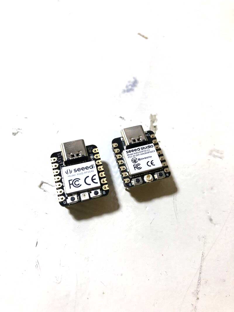
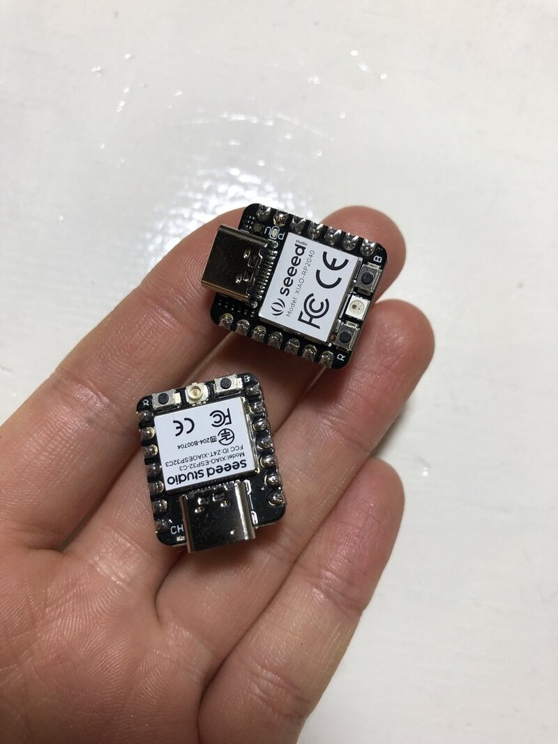
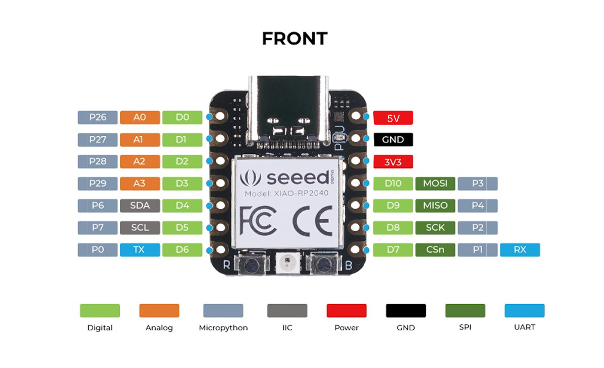
XIAO boards
- The XIAO (name of the size of the board) boards we have now: ESP32-C3 (Espressif) and RP2040 (Raspberry Pi)
- Xiao means tiny but powerful
- We will use these two boards throughout the Fabacademy by soldering header pins onto them and moving them from project to project
- Microcontroller is a microprocessor with added stuff (peripherals; for example ESP32 has WiFi)
- We used to decide on chips depending on the features, but with these it doesn’t really matter anymore because they have so much storage and are very fast
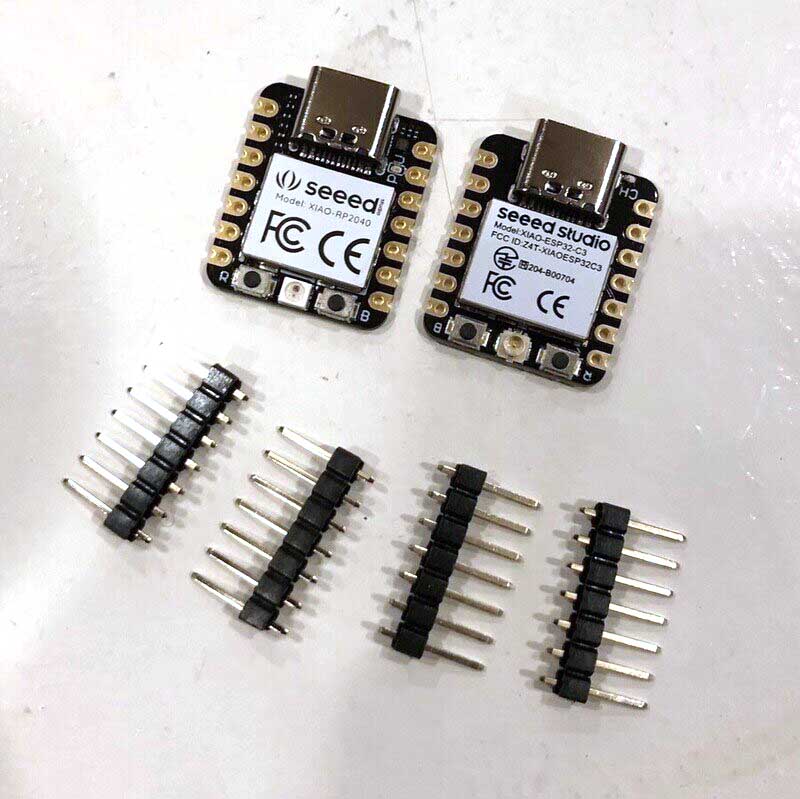

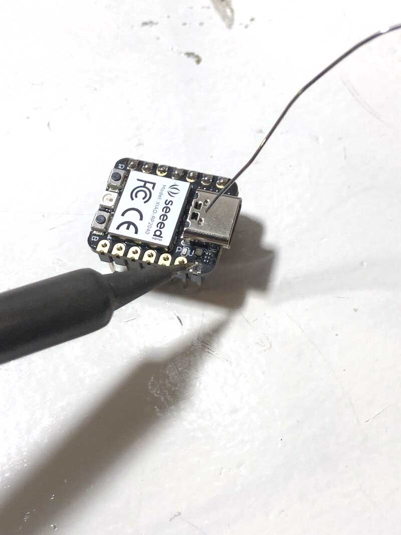
Soldering header pins
We’re starting with soldering header pins to the boards. For all future projects with these chips, we will add pin sockets to the boards and move the board from project to project (unless you’re using another chip).

How to program them
Programming is done via USB cable so that’s pretty easy. Both boards already have a bootloader: a bootloader is a tiny piece of code that tells computers how to deal with the chip, how to communicate; it stays on the chip until you overwrite it. The bootloader on the RP2040 is MicroPython, you can overwrite it with a bootloader by pressing the two buttons on the board to program with C. There is always a fallback to the default bootloader but you have to put the file for it back manually.
- Bootstrapping: sequence of programs that starts up all of the code
It’s probably easiest to pick one language and stick to it, so Python or C (Arduino). For now I’ll stick to Arduino because of its extensive library collection, community and documentation. For programming with Python you can use Thonny.
Setting up the Arduino IDE
The documentation for the XIAO ESP32 can be found here and for the XIAO RP2040 here.
I already have the Arduino IDE installed and I’ve worked with it plenty of times, so I won’t go over the installation steps. I’m working with Arduino 1.8.16 on a Windows 10 computer.
Steps to set up both boards in the Arduino IDE:
- Open the Arduino IDE
- Add
https://raw.githubusercontent.com/espressif/arduino-esp32/gh-pages/package_esp32_dev_index.jsonandhttps://github.com/earlephilhower/arduino-pico/releases/download/global/package_rp2040_index.jsonto the Additional Boards Manager URLs in Preferences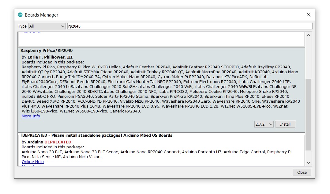
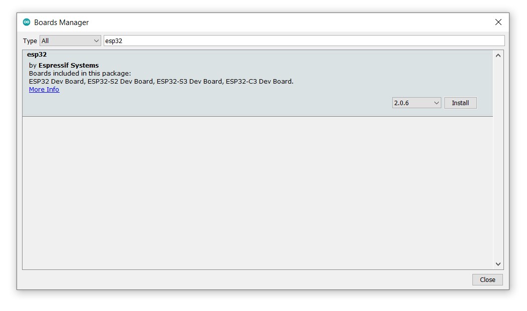
- Install the boards via the Boards Manager. Especially the ESP takes long because the toolchain is much larger than the RP2040 because it has a lot of libraries for its peripherals.
- Select the board you’re working with: in our case either
XIAO_ESP32C3orSeeed XIAO RP2040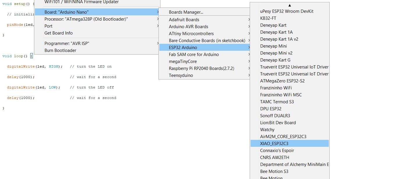
- Connect the boards to your computer with a USB-C cable.
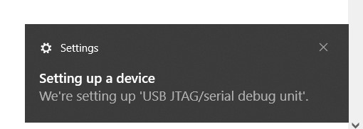
When you connect the boards to your computer, it automatically recognizes the devices:

Blinking an LED
To see if I can program the ESP and the RP2040 I used the following basic Blink sketch (D10 was where I added an external LED to the ESP32 because the XIAO board doesn’t have an integrated LED).
int led = D10;
// when you're programming the RP2040, use the integrated diode on pin 25:
// int led = 25;

void setup() {
  // initialize digital pin led as an output
  pinMode(led, OUTPUT);
}

void loop() {
  digitalWrite(led, HIGH);   // turn the LED on
  delay(1000);               // wait for a second
  digitalWrite(led, LOW);    // turn the LED off
  delay(1000);               // wait for a second
}
Here the LED connected to the ESP32 in action (150 Ohm resistor used):
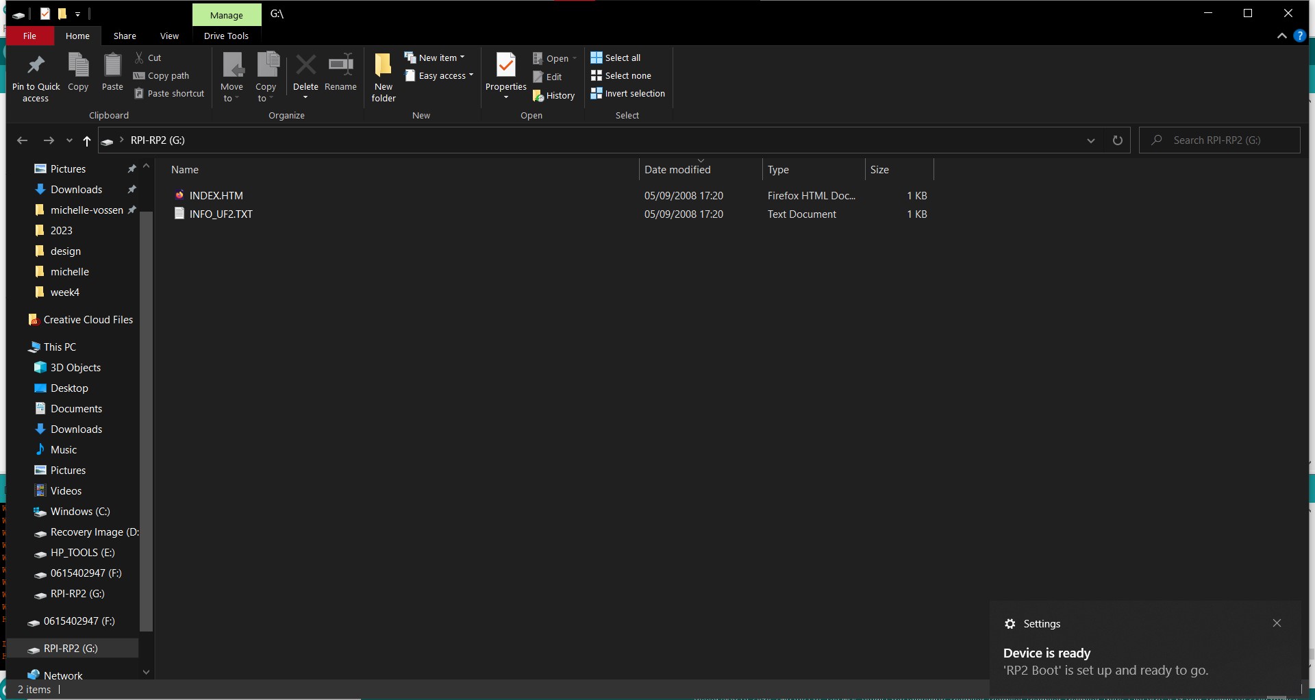
To program the RP2040 with Arduino, you have to press the two buttons on the board until it enters boot mode (your computer will load a removable disk), and you get a message that RP2 BOOT is set up. If you want to go back to MicroPython you need to get the file from here and put it back onto the drive.
Here the integrated LED on the RP2040 in action:
Comparing architectures
For the group assignment this week, we have to compare the performance and development workflow for different architectures. Architectures are basically families of chips, so for example ARM vs ATMEL vs Extensa.
- ESP: Extensa architecture
- RP: ARM architecture
- ATtiny/ATmega: ATMEL architecture
We’re going to compare the RP2040 with the ESP32C3 and also have a look at the Arduino Uno (ATmega328P) and the ATtiny24A/44A/84A.
Performance
| done | compare calculation speeds |
| done | compare bit depth values |
| done | features table |
Development workflow
| done | compare Arduino (C) code and Arduino IDE vs MicroPython Thonny IDE workflows, compare C vs Arduino, Arduino workflow VSC with PlatformIO |
| done | describe the steps to program |
| done | compare compiling times |
Features
| Features | ATTiny 24A/44A/84A | XIAO RP2040 |
|---|---|---|
| CPU | single core AVR processor | Dual-core ARM Cortex M0+ processor |
| Clock speed | internal 1 MHz or 8 MHz, external up to 20 MHz | Flexible clock running up to 133 MHz, can be overclocked to 300 MHz |
| Bit depth | 8-bit | 32-bit |
| Storage | 128/256/512 Bytes of internal SRAM; 128/256/512 Bytes of In-System Programmable EEPROM; 2K/4K/8K Bytes of In-System, Self-programmable Flash Program Memory | 264 kB of embedded SRAM (Static Random Access Memory); 2MB of on-board Flash memory |
| I/O pins | 12 I/O pins | 11 digital pins, 4 analog pins, 11 PWM Pins |
| Power | 1.8 – 5.5V | 3.3V/5V DC; USB Type-C connection or power pads on the bottom to connect a battery power supply |
| Dimensions | 6x8.7x1.65mm (including legs) | 20×17.5×3.5mm (entire board) |
| Bluetooth | no (only with external module) | no (only with external module) |
| WiFi | no | no |
| How to program | Arduino as ISP (in system programmer), USBTinyISP, UPDI | USB-C cable directly to board |
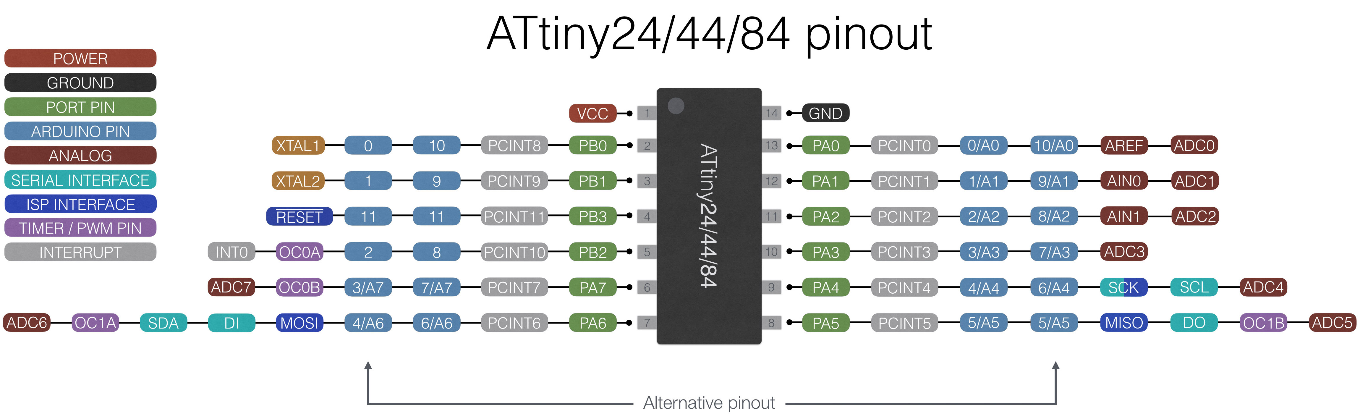
Pin-out ATT
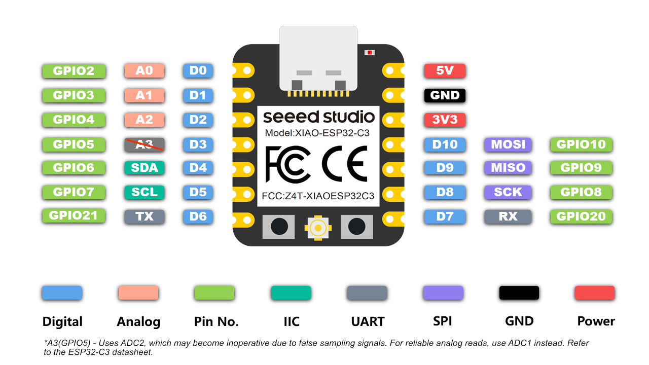
Pin-out XIAO ESP32-C3
Pin-out XIAO RP2040
Resolution
- The Sizeof operator returns the number of bytes in a variable type, or the number of bytes occupied by an array.
- Printf doesn’t work with Arduino Uno; Pieter sent me his test code that used printf and the code above is the adaptation of his code
This comparison isn’t really necessary for the performance comparison, but it is something that can be an issue if you don’t know about it which was the case for me. To compare resolution or bit depth for 8 bit vs 32 bit architectures I’ve used the following code:
String str;

void setup() {
  Serial.begin(9600);
  while (!Serial) {
    ; // wait for serial port to connect. Needed for native USB port only
  }
  Serial.println(str + "size of byte: " + sizeof(byte));
  Serial.println(str + "size of int: " + sizeof(int));
  Serial.println(str + "size of long: " + sizeof(long));
  Serial.println(str + "size of float: " + sizeof(float));
  Serial.println(str + "size of double: " + sizeof(double));
  Serial.println(str + "size of int32_t: " + sizeof(int32_t));
  Serial.println(str + "size of int64_t: " + sizeof(int64_t));
  Serial.println(str + "size of String: " + sizeof(String));
}

void loop() {
}
This is the output on the RP2040:

And this on Arduino:
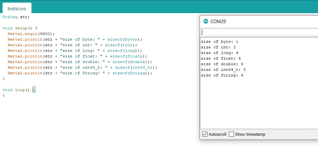
Results
| Resolution of: | RP2040 (32 bit) & ESP32C3 | Arduino Uno (8 bit) |
|---|---|---|
| int | 2 | 4 |
| long | 4 | 4 |
| float | 4 | 4 |
| double | 8 | 4 |
| int32_t | 4 | 4 |
| int64_t | 8 | 8 |
| String | 12 | 6 |
Speed test
Making the test
We’re going to have the different microcontrollers execute a bunch of complicated calculations and measure how long it takes them so we can determine their speed.
- Open the serial port with Serial.begin(9600);
- Making a stopwatch with two millis functions
- Put the calculation in between the two millis functions
- Measure the time difference between the two millis functions
This sounds easy enough, but the first results were a bit strange:
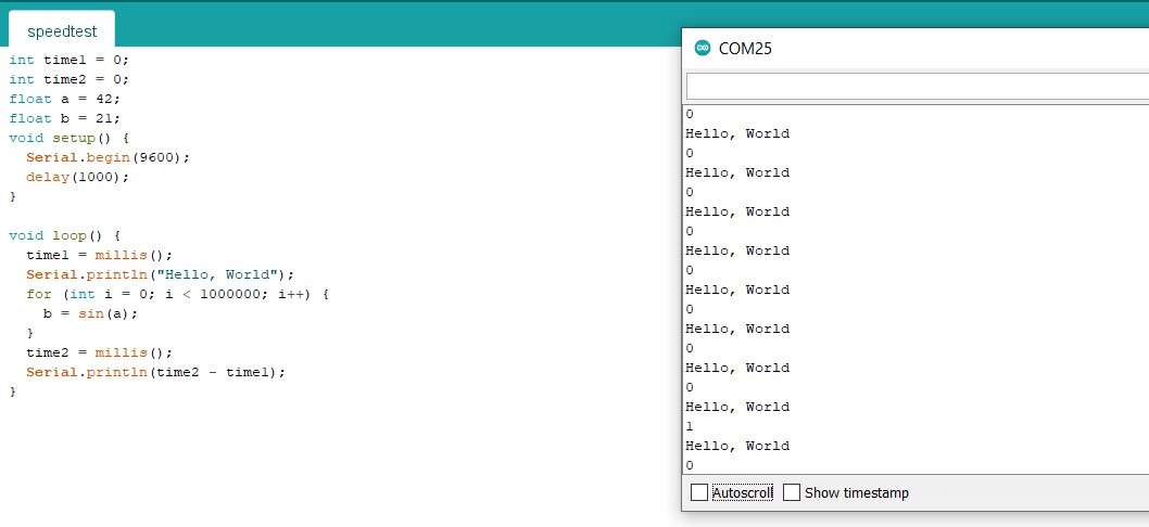
It’s pretty unlikely that it takes less than one millisecond to do one million calculations. Bas suggested that Arduino may be smarter than we want it to be. Two possible reasons why it’s not working:
- Right now we are asking the chip to perform the same calculation one million times, so it may be that instead the calculation is just done once
- We are also not asking for the answer of the calculation outside of the for loop, so maybe the for loop is just skipped entirely
Both possibilities are easy to tackle: the first one can be solved by changing the calculation for every iteration of the loop by taking the sine of i (or j, which is what I did; for no other reason than that I first added another for loop around the current for loop, then removed the initial loop). I also used b += instead of b =, so that Arduino can’t cheat by only taking the last value of j (which seems unlikely to me, but at least now we’re sure that every calculation has to be executed). The second issue can be solved by printing the answer to the serial monitor.
I tried the code with 100, 1000, 10000, 100000 and 1000000 iterations for the ESP with the following results (to see what range would be reasonable and to see if there would be a direct correlation between time and amount of calculations).
| Iteration count | Time (milliseconds) |
|---|---|
| 100 | 3/4 |
| 1000 | 33 |
| 10000 | 334/335 |
| 100000 | 3741 |
| 1000000 | 39820 |
You can see that when there are more calculations, it takes relatively longer to perform all of the calculations. I settled on 100000 iterations because I wanted as many as possible without waiting too long.
So with this code I measured the calculation speed of the different chips:
int time1 = 0;
int time2 = 0;
double b = 0;
void setup() {
Serial.begin(9600);
delay(1000);
}
void loop() {
Serial.println("Initializing");
b = 0;
time1 = millis();
for (int j = 0; j < 100000; j++) {
b += sin(j);
}
time2 = millis();
//Serial.println(b);
Serial.print(time2 - time1);
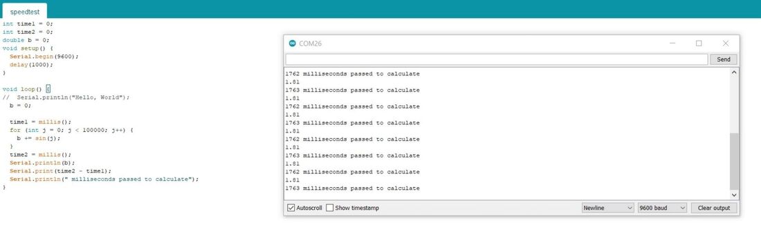
Serial.println(" milliseconds passed to calculate");
}
Test results
ESP results:
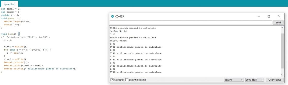
RP2040 results:
Arduino Uno
I also wanted to compare these results to how fast an Arduino Uno would be. I uploaded the same code as before and waited for about two minutes, but I got no answer. I thought it was just taking long, but Bas said that I would probably have to wait forever because integers on an Arduino Uno have a lower maximum value than on the RP2040 and ESP32. This is because these chips are 32 bit while Arduino Uno is 8 bit.
This can be resolved by using uint32_t instead of int. Using this makes sure that integers have a resolution of 4 bytes (32 bits) instead of 2 bytes (16 bits).
Integers are signed values meaning they can be negative; the last bit is the sign bit making it positive or negative. On ATMEGA boards like Arduino Uno integers can have a range of -32,768 to 32,767 (minimum value of -2^15 and a maximum value of (2^15) - 1). Since we don’t need negative numbers here, we can use unsigned integers; using the uint32_t gives us a range from 0 to 4,294,967,295 (2^32 - 1). That’s more than enough.
With this changed in the code from above, these were the results for Arduino Uno:

Summary and reflection
So to summarize:
| ESP32C3 | RP2040 | Arduino Uno |
|---|---|---|
| 3741ms | 1763ms | 13538ms |
The RP2040 is a clear winner, followed by the ESP. The Uno is almost 8 times slower than the RP2040.
One thing to consider about this speed test, is its relevance. For most projects, you wouldn’t have to do so many calculations. For simple electronics projects, Arduino Uno works just fine. Only if you have something that depends on a lot of fast calculations you may run into speed issues.
Compiling and uploading times
Measured in Arduino IDE with the speedtest code as code.
| Time | ESP32C3 | RP2040 | Arduino Uno |
|---|---|---|---|
| Compiling time | 23s | 16s | 11s |
| Uploading time | 8s | 5s | 4s |
Development workflows
We distributed describing workflows; Samson describes the workflow with Arduino code in the Arduino IDE, Pieter the workflow with Python code in the Thonny IDE and I’m looking into cpp (Arduino) code in Visual Studio Code with PlatformIO.
PlatformIO in VSC - RP2040
PlatformIO is a plugin for VSC that I’ve used for updating firmware for 3D printers in the past (if I remember correctly). It seemed pretty nice, so I decided to have a look at it. Comparison (from this tutorial):
| Arduino IDE | PlatformIO |
|---|---|
| Does not have a debugger. | Has an integrated debugger. |
| It does not have autocomplete suggestions for code. | Can suggest code as you type. |
| Easy to use. | Has a little learning curve. |
| Does not have embedded Git. | Git integration. |
| Supports C/C++ programming languages. | Supports a wide range of languages such as Python, Java, C/C++, Javascript etc. |
I already had the PlatformIO extension installed; it can be downloaded via the extensions tab in VSC. After that it appears as a little alien in the side bar on the right.

It opens up the PIO Home as another tab in VSC alongside any other open projects (perfect for documenting as you go?!).

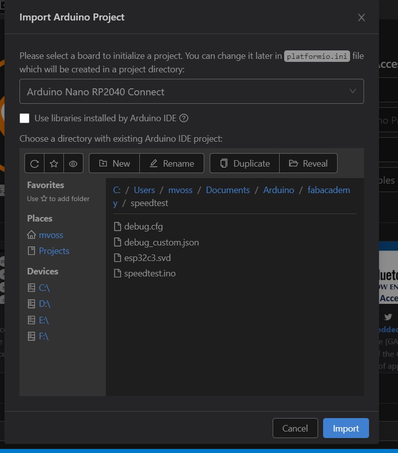
Open up the PlatformIO tab and click on Create New Project or Import Arduino Project. You can change the board later if it’s not in the list.
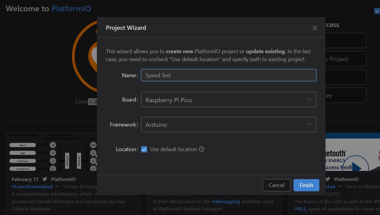
You can also work from an existing Arduino project, which is what I did; I imported the speed test project.
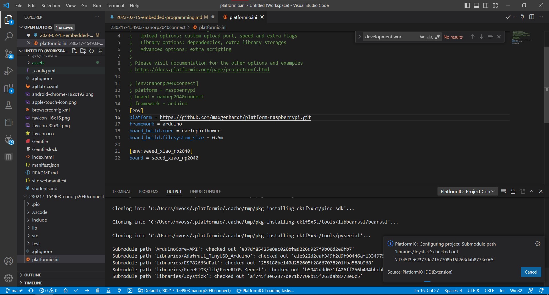
Add board to platformio.ini and disable what is already there (https://community.platformio.org/t/support-for-seeed-xiao-rp2040/28989/2) with the following code:
[env]
platform = https://github.com/maxgerhardt/platform-raspberrypi.git
framework = arduino
board_build.core = earlephilhower
board_build.filesystem_size = 0.5m

[env:seeed_xiao_rp2040]
board = seeed_xiao_rp2040
This starts installing all of the dependencies it needs (which takes a while).
After that I hoped that it would work immediately, but I kept running into this error:
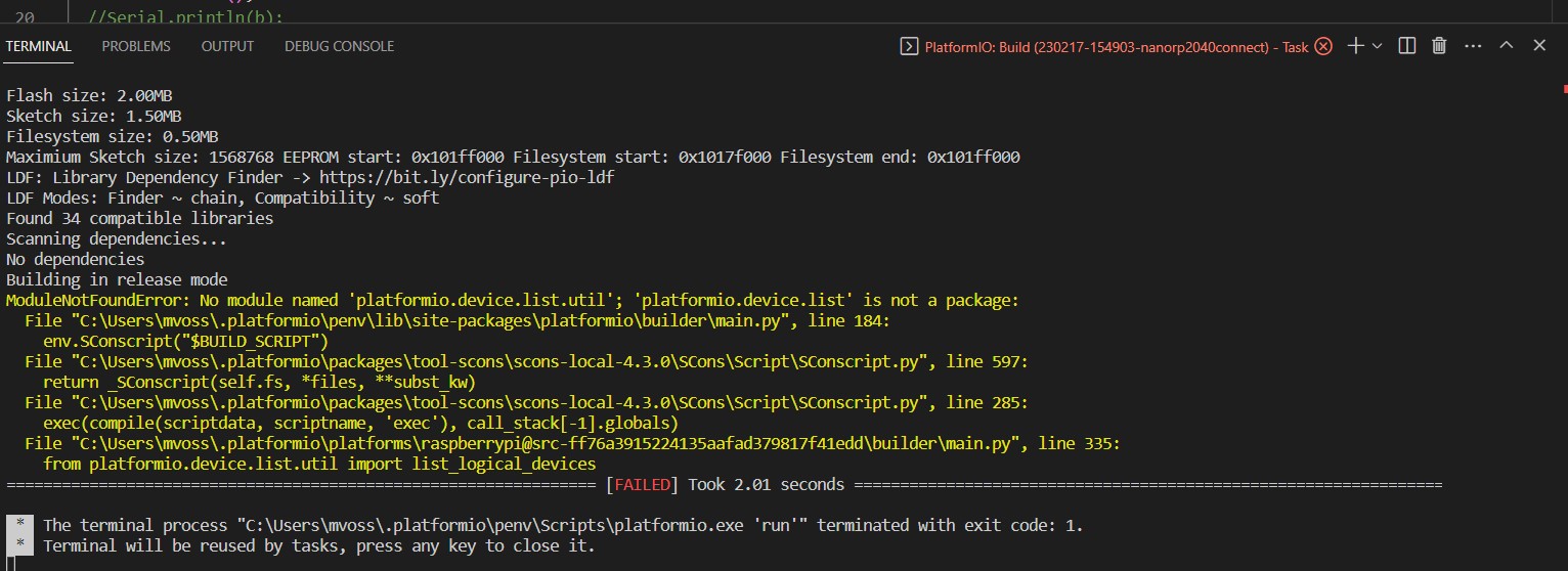
Error: Processing seeed_xiao_rp2040 (board: seeed_xiao_rp2040; platform: https://github.com/maxgerhardt/platform-raspberrypi.git; framework: arduino)
...
Building in release mode
ModuleNotFoundError: No module named 'platformio.device.list.util'; 'platformio.device.list' is not a package:
  File "C:\Users\mvoss\.platformio\penv\lib\site-packages\platformio\builder\main.py", line 184:
    env.SConscript("$BUILD_SCRIPT")
  File "C:\Users\mvoss\.platformio\packages\tool-scons\scons-local-4.3.0\SCons\Script\SConscript.py", line 597:
    return _SConscript(self.fs, *files, **subst_kw)
  File "C:\Users\mvoss\.platformio\packages\tool-scons\scons-local-4.3.0\SCons\Script\SConscript.py", line 285:
    exec(compile(scriptdata, scriptname, 'exec'), call_stack[-1].globals)
  File "C:\Users\mvoss\.platformio\platforms\raspberrypi@src-ff76a3915224135aafad379817f41edd\builder\main.py", line 335:
    from platformio.device.list.util import list_logical_devices
======================== [FAILED] Took 1311.00 seconds ========================
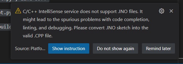
I tried the following things to fix it:
- Convert .ino file to .cpp file manually if it didn’t convert automatically. Steps:
- Add #include
at the top of the source file - Declare each custom function (excluding built-in, such as setup and loop) before it will be called
- Save as .cpp file
- Add #include
- I tried updating PIO, that didn’t help
- renamed speedtest.cpp to main.cpp
- Opened the blink arduino example in PlatformIO
When using the following settings (that are part of the list you can choose from in PlatformIO), the code builds just fine, just like replacing the speedtest code with the blink code, so there is definitely something wrong with the env I tried to use; either fails.
[env]
platform = raspberrypi
framework = arduino

[env:pico]
board = pico

[env:nanorp2040connect]
board = nanorp2040connect
Then I got new errors:
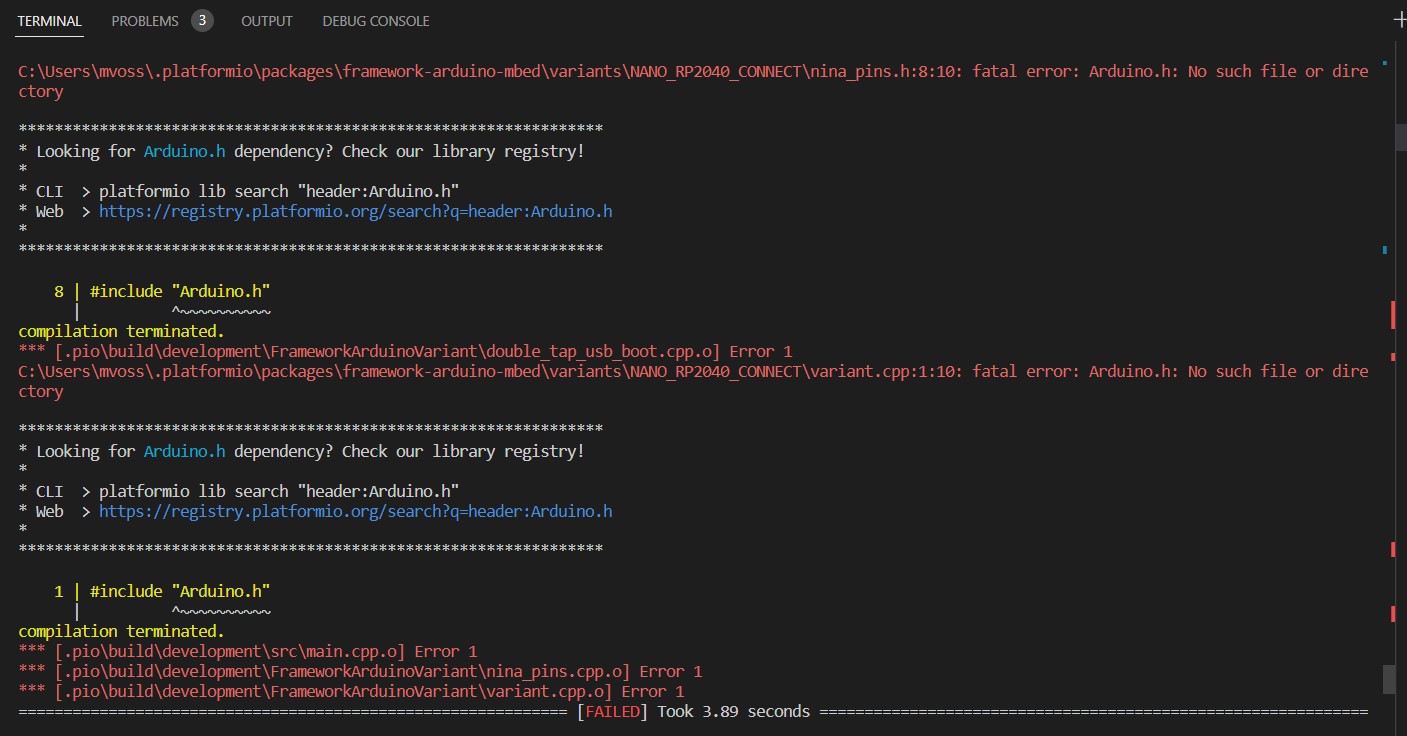
I tried this to remove the folder C:\Users\<user>\.platformio\packages\framework-arduino-avr, C:\Users\<user>\.platformio\.cache and C:\Users\<user>\.platformio\platforms\atmelavr (plus all of the other frameworks just to be sure) and then rebuild as suggested here. That resulted in an *** [upload] Error 1; also after a pio run -v -t upload command in the terminal for verbose upload as suggested here.
Then I saw this error that it couldn’t find the serial port, and the auto-detect didn’t detect the right port. The person in the forum had a similar issue. It detected port 12 while it should be port 26.

Once I set it manually to the correct port, I still got an error 1. At this point I found new settings to try out (from the platform-raspberrypi github).
These were the last settings I had in the platformio.ini file (pico added because then I can see if one of them works and one of them doesn’t):
[env]
platform = https://github.com/maxgerhardt/platform-raspberrypi.git
framework = arduino
board_build.core = earlephilhower
board_build.filesystem_size = 0.5m

[env:pico]
board = pico

[env:seeed_xiao_rp2040]
board = seeed_xiao_rp2040
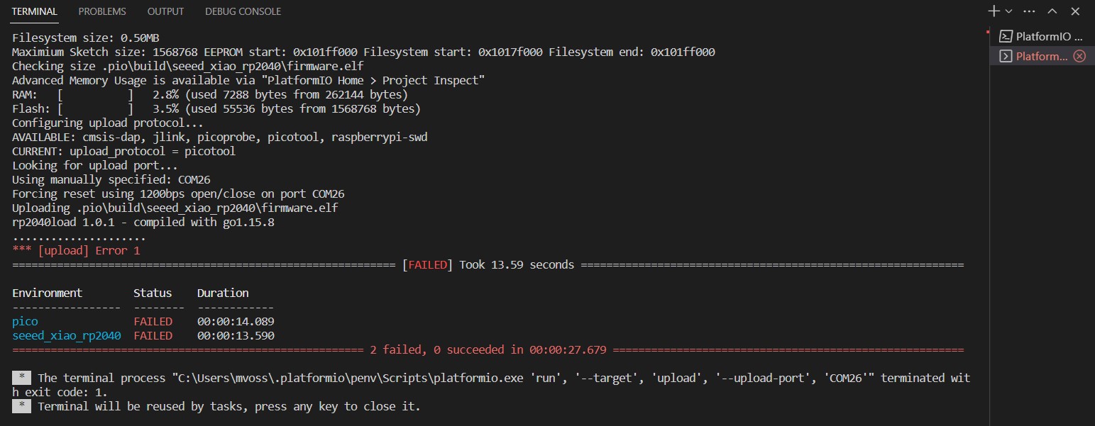
After this, I didn’t really know what to do anymore, so I did something else. In the evening I tried building the Blink example again, and that built succesfully:
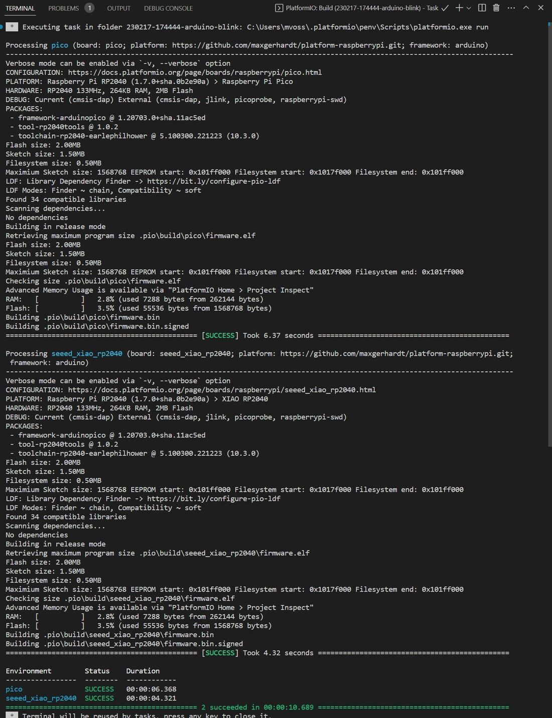
So I ran to grab the RP2040, but uploading just caused the upload error 1 again; which did make sense because before it already said that it went wrong when uploading. I tried out a suggestion from here, so setting the env:seeed_xiao_rp2040 in the bottom blue menu, and adding an upload protocol to the .ini file. If I upload it like this, I get a warning that the upload protocol is unknown, but the upload does succeed according to the terminal. If I remove that line, the upload fails. In both cases, the upload doesn’t actually succeed though, so I’m not sure if I’m one step further.
[env:seeed_xiao_rp2040]
platform = https://github.com/maxgerhardt/platform-raspberrypi.git
framework = arduino
board_build.core = earlephilhower
board_build.filesystem_size = 0.5m
upload_protocol = sam-ba
board = seeed_xiao_rp2040
Opinion
So I didn’t get it to work with the RP2040 so far. Henk got the ESP32 working easily, so I’ll also have a look at that, because now I got stuck on endless troubleshooting. What that tells me is that it was true that it has a learning curve that is a little steeper than Arduino; the Arduino IDE and language work well together, and there is a lot of documentation available if you don’t know what to do.
Another thing that I noticed is that I was really annoyed that PlatformIO is within VSC, the place where I document. I am so used to alt + tab my way around my computer, that I kept losing where I was documenting. Of course I could have opened a new window for PlatformIO, but I didn’t do that because I tried to get used to it. So far it didn’t make me document faster sadly. I will try PlatformIO again though, because I like the command line and debugging tools that are available.
Interaction
Button with LED
I’ve already tried blinking an LED with both boards and printing something to the serial monitor, but now it’s time to make something more interactive. Henk gave us a button, some resistors and an LDR (light dependent resistor), and we have some LEDs to our disposal.
I started out with the example code that Henk sent to us which is this:
/*
  Fab Academy 2023
  Embedded programming
  XIAO ESP32-C3

  This example code is in the public domain.

  ! Button!

  Turns on and off a light emitting diode(LED) connected to digital pin D8,
  when pressing a pushbutton attached to pin D0.

  The circuit:
  - LED attached from pin D8 to ground through 220 ohm resistor
  - pushbutton attached to pin D0 from +5V
  - 10K resistor attached to pin D0 from ground

  See Serial Console and Plotter!

  https://www.arduino.cc/en/Tutorial/BuiltInExamples/Button
*/

// constants won't change. They're used here to set pin numbers:
const int buttonPin = D0;     // the number of the pushbutton pin
const int ledPin =  D8;      // the number of the LED pin

// variables will change:
int buttonState = 0;         // variable for reading the pushbutton status

void setup() {
  // initialize the LED pin as an output:
  pinMode(ledPin, OUTPUT);
  // initialize the pushbutton pin as an input:
  pinMode(buttonPin, INPUT);
  Serial.begin(9600);
}


void loop() {
  // read the state of the pushbutton value:
  buttonState = digitalRead(buttonPin);

  // check if the pushbutton is pressed. If it is, the buttonState is HIGH:
  if (buttonState == HIGH) {
    // turn LED on:
    digitalWrite(ledPin, HIGH);
    Serial.println("ON");

  } else {
    // turn LED off:
    digitalWrite(ledPin, LOW);
    Serial.println("OFF");
  }
}

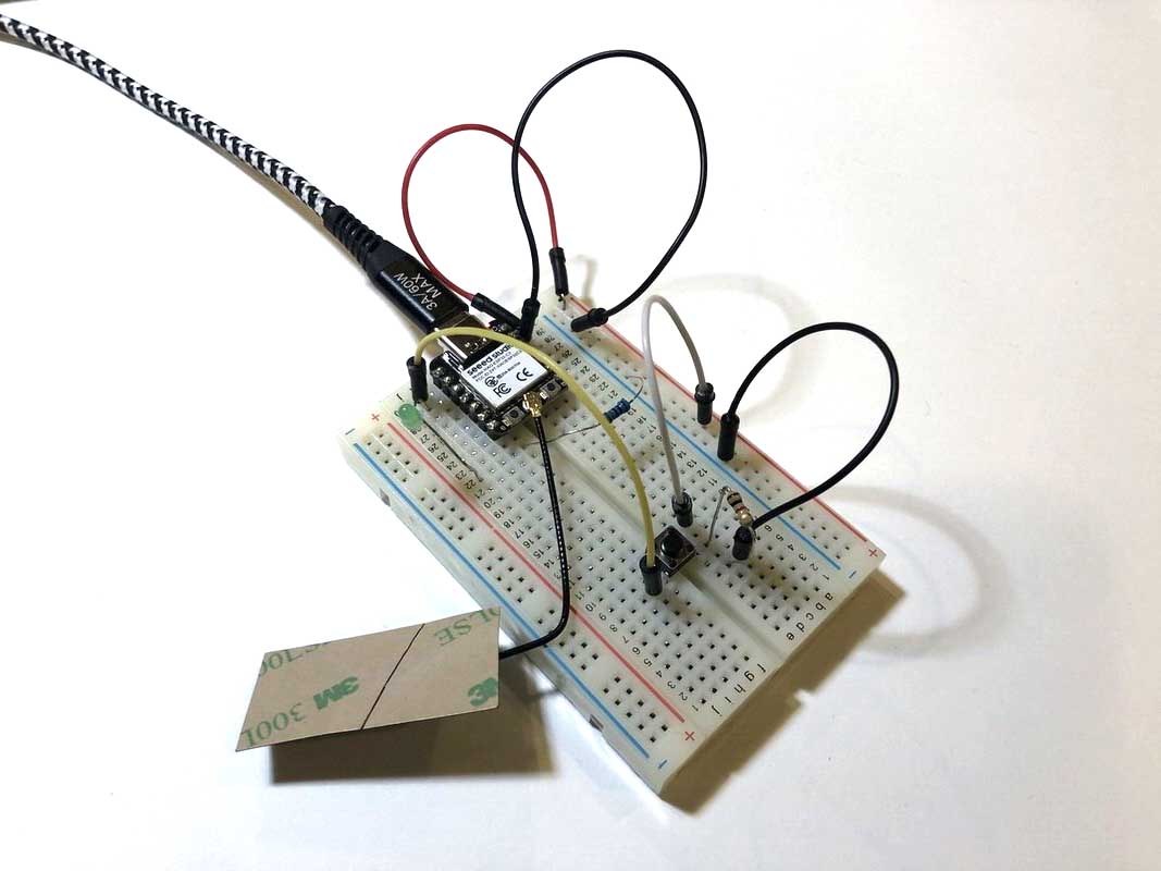
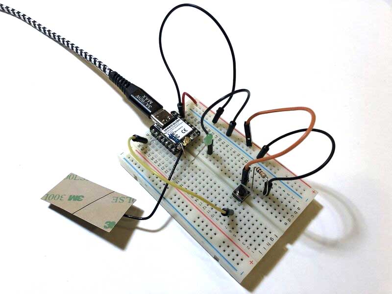
The code above is pretty simple: turn on an LED while a button is pressed. My first attempt wasn’t wired correctly (red lines are where the legs of the button are connected), so that’s why the behavior of the LED is a little random. The serial port was working fine.
I rewired the button correctly, but now nothing was working anymore, so I was pretty confused since it’s a simple circuit. After checking all of the wiring I looked up again how to wire an LED and swapped the direction of the LED and resistor (see pictures); I don’t think it actually mattered. I tried a simple LED Blink sketch which worked fine (but it also worked before), but the button didn’t do anything and the serial port didn’t open.
I added this to the setup to check:
while (!Serial);
Serial.begin(9600);
Serial.println("Serial port opened");
And it didn’t open the serial port; adding a delay also didn’t help. I tried an ASCII table dump to see if the serial monitor opened which also worked fine. I then tried to upload the sketch that Henk sent (only changing to correct pins) which worked for some reason although both were almost identical (only printing some extra lines to the serial monitor). When I modified my code to be the same as Henks code, it didn’t work. Then I tried to upload Henks code again and then it also didn’t work anymore, leaving me very confused because it seems very random. Now nothing worked anymore. So I went for lunch.
After a bit of fiddling again (and restarting my computer) I uploaded a Blink sketch that didn’t work, then pressed the reset button on the board to see if it would help, and magically, it did. So that’s one to keep in mind.
Now to change the code, I wanted to change the blinking behavior of the LED based on various button inputs. I have written this code before to switch between neopixel color modes (not the full code, only the relevant loop):
void lightSwitcher() {
  currentState = digitalRead(pushButton);
  int sensorValue = analogRead(potSensor);

//  Serial.println("lightSwitcher loop start");
//  Serial.print(sensorValue);  // potentiometer value 0-1023
//  Serial.println(" potentiometer value");
  Serial.print(currentState); // HIGH (1) or LOW (0), button pressed or not pressed
  Serial.println(" button value");

  if (currentState != lastState) {
    if (currentState == LOW) {
      hits = hits + 1;
      Serial.print(hits);
      Serial.println(" hits");
      delay(1);
    }
  }

  if (hits == 0) {
    whiteLight();
  }

  if (hits == 1) {
    rainbow(1);
    hits = hits + 1; // otherwise we can't exit the rainbow part
  }

  if (hits == 3) {
    potentioMeter();
  }

  if (hits == 4) {
    whiteLight();
    if (currentState != lastState) {
      if (currentState == LOW) {
        hits = 0;
        Serial.println(hits);
        Serial.println("reset hits");
      }
    }
  }
}
Toggle switch
I’m going to adapt this to blink LEDs at different intervals, using the button as a toggle switch. This is the first iteration:
int lastState = LOW; // the previous state from the input pin
int currentState = LOW;    // the current reading from the input pin
static int hits = 0;

// constants won't change. They're used here to set pin numbers:
const int buttonPin = D0;     // the number of the pushbutton pin
const int ledPin =  D1;      // the number of the LED pin

// variables will change:
int buttonState = 0;         // variable for reading the pushbutton status

void setup() {
  // initialize the LED pin as an output:
  pinMode(ledPin, OUTPUT);
  // initialize the pushbutton pin as an input:
  pinMode(buttonPin, INPUT);
  Serial.begin(9600);
  while (!Serial) {
    ; // wait for serial port to connect. Needed for native USB port only
  }
}

void loop() {
  // read the state of the pushbutton value:
  buttonSwitcher();
}

void buttonSwitcher() {
  currentState = digitalRead(buttonPin);

  //  Serial.println(buttonSwitcher loop start");
  Serial.print(currentState); // HIGH (1) or LOW (0), button pressed or not pressed
  Serial.println(" button value");

  if (currentState != lastState) {
    if (currentState == HIGH) {
      hits = hits + 1;
      Serial.print(hits);
      Serial.println(" hits");
      delay(1);
    }
  }

  if (hits == 0) {
    digitalWrite(ledPin, LOW);
  }

  if (hits == 1) {
    digitalWrite(ledPin, HIGH);
    delay(500);
    digitalWrite(ledPin, LOW);
    delay(500);
    digitalWrite(ledPin, HIGH);
    delay(500);
    digitalWrite(ledPin, LOW);
    delay(500);
  }

  if (hits == 2) {
    digitalWrite(ledPin, HIGH);
    delay(250);
    digitalWrite(ledPin, LOW);
    delay(250);
    digitalWrite(ledPin, HIGH);
    delay(250);
    digitalWrite(ledPin, LOW);
    delay(250);
  }

  if (hits == 3) {
    digitalWrite(ledPin, HIGH);
    delay(100);
    digitalWrite(ledPin, LOW);
    delay(100);
    digitalWrite(ledPin, HIGH);
    delay(100);
    digitalWrite(ledPin, LOW);
    delay(100);
  }


  if (hits == 4) {
    if (currentState != lastState) {
      if (currentState == HIGH) {
        hits = 0;
        Serial.println(hits);
        Serial.println("reset hits");
      }
    }
  }
}
Here is the result:
With this code, you need to time when you press the button, which is inconvenient. The program needs to finish a loop before it can read the change in button state. It works slightly better when you remove the second half of the three blinking patterns (they’re the same as the first half anyway). But it’s still not optimal. I looked into better ways to do it, and I found this sketch here about debouncing buttons. Basically what it does is just adding a delay of 100ms so it allows reading the changed button state without interference from a button that is pressed and vibrating slightly. This is the sketch without debouncing:
Note: a ! is a boolean operator called logical NOT which turns TRUE into FALSE and vice versa. With the slightly modified code below you get a better toggle, but it doesn’t toggle between multiple states which is what I would want.
#define BUTTON_PIN D0
#define LED_PIN D1
#define buttonState digitalRead(BUTTON_PIN)
#define hits = 0;

void setup() {
  Serial.begin(9600);
  pinMode(BUTTON_PIN, INPUT);
  pinMode(LED_PIN, OUTPUT);
}

void loop() {
  static byte toggle_sw_memory = 1;
  Serial.print(toggle_sw_memory); // HIGH (1) or LOW (0), button pressed or not pressed
  Serial.println(" toggle state");
  Serial.print(buttonState); // HIGH (1) or LOW (0), button pressed or not pressed
  Serial.println(" button state");
  // Check for keypress
  if ( !digitalRead(BUTTON_PIN) ) {           // if button is not pressed (LOW)
    delay(100);
    if ( !digitalRead(BUTTON_PIN) ) {         // if it is still not pushed after a delay, so still LOW
      toggle_sw_memory = !toggle_sw_memory; // change the toggle memory from 1 to 0 or 0 to 1
      if (toggle_sw_memory)                  // if the toggle is 1
        digitalWrite(LED_PIN, HIGH);          // led on
      else
        digitalWrite(LED_PIN, LOW);           // led off
    }
    while (!digitalRead(BUTTON_PIN)); // wait for low; while button is not pressed
  }

}
This is the better toggle with the code above:
I tried combining these two codes to make a better toggle but it didn’t work, and at some point I didn’t really know what I was doing anymore and it felt a little useless in any case so I went on to the next spiral. Below the two codes that are not working. Maybe they can be a useful starting point in a future project.
#define BUTTON_PIN D0
#define LED_PIN D1
#define buttonState digitalRead(BUTTON_PIN)
#define hits = 0;

void setup() {
  Serial.begin(9600);
  pinMode(BUTTON_PIN, INPUT);
  pinMode(LED_PIN, OUTPUT);
}

void loop() {
  static byte toggle_sw_memmory = 0;
  Serial.print(toggle_sw_memmory); // HIGH (1) or LOW (0), button pressed or not pressed
  Serial.println(" toggle state");
  Serial.print(buttonState); // HIGH (1) or LOW (0), button pressed or not pressed
  Serial.println(" button state");
  // Check for keypress
  if ( digitalRead(BUTTON_PIN) ) {         // if button is pressed (HIGH)

    delay(100);

    if ( digitalRead(BUTTON_PIN) ) {       // if it is still pushed after a delay.
      toggle_sw_memmory += 1; // change the toggle memory from 1 to 0 or 0 to 1

      if (toggle_sw_memmory == 1)                  // if the toggle is 1
        digitalWrite(LED_PIN, HIGH);
        delay(100);
        digitalWrite(LED_PIN, LOW);
        delay(100);

      if (toggle_sw_memmory == 2)
        digitalWrite(LED_PIN, HIGH);
        delay(500);
        digitalWrite(LED_PIN, LOW);
        delay(500);
      if (toggle_sw_memmory == 3)
        digitalWrite(LED_PIN, LOW);           // led off
        toggle_sw_memmory == 0;
    }
    while (!digitalRead(BUTTON_PIN)); // wait for low; while button is not pressed
  }

}

=============================================================================

int lastState = LOW; // the previous state from the input pin
int currentState = LOW;    // the current reading from the input pin
static int hits = 0;

// constants won't change. They're used here to set pin numbers:
const int buttonPin = D0;     // the number of the pushbutton pin
const int ledPin =  D1;      // the number of the LED pin

// variables will change:
int buttonState = 0;         // variable for reading the pushbutton status

void setup() {
  // initialize the LED pin as an output:
  pinMode(ledPin, OUTPUT);
  // initialize the pushbutton pin as an input:
  pinMode(buttonPin, INPUT);
  Serial.begin(9600);
}


void loop() {
  // read the state of the pushbutton value:
  buttonSwitcher();

}

void buttonSwitcher() {
  currentState = digitalRead(buttonPin);
  static byte toggle_sw_memory = 0;

  //  Serial.println(buttonSwitcher loop start");
  Serial.print(currentState); // HIGH (1) or LOW (0), button pressed or not pressed
  Serial.println(" button value");

  if ( currentState ) {           // if button is pressed (HIGH)
    delay(100);
    if ( currentState ) {         // if it is still pushed after a delay, so still HIGH
      toggle_sw_memory = !toggle_sw_memory; // change the toggle memory from 1 to 0 or 0 to 1
      if (toggle_sw_memory) {                  // if the toggle is 1
        hits = hits + 1;
      }
      else
        digitalWrite(ledPin, LOW);           // led off
    }
    while (digitalRead(buttonPin)); // wait for low; while button is not pressed
  }

  if (hits == 0) {
    digitalWrite(ledPin, LOW);
  }

  if (hits == 1) {
    digitalWrite(ledPin, HIGH);
    delay(1000);
    digitalWrite(ledPin, LOW);
    delay(500);
    digitalWrite(ledPin, HIGH);
    delay(1000);
    digitalWrite(ledPin, LOW);
    delay(500);
  }

  if (hits == 2) {
    digitalWrite(ledPin, HIGH);
    delay(500);
    digitalWrite(ledPin, LOW);
    delay(250);
    digitalWrite(ledPin, HIGH);
    delay(500);
    digitalWrite(ledPin, LOW);
    delay(250);
  }

  if (hits == 3) {
    if (currentState != lastState) {
      if (currentState == HIGH) {
        hits = 0;
        Serial.println(hits);
        Serial.println("reset hits");
      }
    }
  }
}
LDR
I was a little fed up with the ESP so I went back to the RP2040 to try out the LDR sketch that Henk sent us:
/*
  Fab Academy 2023
  Embedded programming
  XIAO ESP32-C3

  This example code is in the public domain.

  ! LDR !


  Connect 1 ldr leg to 5V, the other to D0
  and through 10K resistor to GND.

  See serial and plotter for values!

*/

#define LDRpin D0 // pin where we connected the LDR and the 10K resistor
#define LEDpin D1 // pin where we connected the LDR and the 10K resistor

int LDRValue = 0;     // result of reading the analog pin
int mappedValue = 0;

void setup() {
  Serial.begin(9600); // sets serial port for communication
}

void loop() {
  LDRValue = analogRead(LDRpin); // read the value from the LDR
  mappedValue = map(LDRValue, 100, 310, 0, 255);
  analogWrite(LEDpin, mappedValue);
  Serial.print(LDRValue);      // print the value to the serial port
  Serial.println(": LDR value");      // print the value to the serial port
  Serial.print(mappedValue);      // print the value to the serial port
  Serial.println(": mapped value");      // print the value to the serial port

  delay(100);                    // wait a little
}
Here you can see the values changing when my hand blocks the LDR:
Fading an LED
Then I tried the code to fade an LED which wasn’t too exciting. Here is the result; the LED fades out then starts at full power again.
Fading an LED with LDR
Now I’m going to adapt combine the two to have the LDR value as input for the LED output. For this we need PWM: pulse width modulation.
PWM signal ranges between 0 to 255. Where 255 represents 5 volts and 0 represents 0 volts. 127 represents 2.5 volts. (via https://www.engineersgarage.com/fading-led-with-ldr-using-arduino/)
I figured the easiest way to do this was by mapping the data. In this tutorial they’re just dividing the LDR value output by 4, because the LDR range can be from 0 to 1023, and the PWM analogWrite range is from 0 to 255. I think mapping is better, because then I have more control over the ranges. I noticed that only with a bright flashlight the LDR value reaches its max value, so with mapping I can play around more.
This is the result of the values mapped from full range to full range; in the video you can’t see any difference but you could see a slight change IRL.
And this with the LDR range mapped from 100-310 to 0-255. Here you can clearly see a change in brightness.
Code:
#define LDRpin D0 // pin where we connected the LDR and the 10K resistor
#define LEDpin D1 // pin where we connected the LDR and the 10K resistor

int LDRValue = 0;     // result of reading the analog pin
int mappedValue = 0;  // mapped value of analog pin

void setup() {
  Serial.begin(9600); // sets serial port for communication
}

void loop() {
  LDRValue = analogRead(LDRpin); // read the value from the LDR
  mappedValue = map(LDRValue, 100, 310, 0, 255);
  analogWrite(LEDpin, mappedValue);
  Serial.print(LDRValue);      // print the value to the serial port
  Serial.println(": LDR value");      // print the value to the serial port
  Serial.print(mappedValue);      // print the value to the serial port
  Serial.println(": mapped value");      // print the value to the serial port

  delay(100);                    // wait a little
}
Communication
Serial
I used the following code from the walkthrough from before to try out serial communication. It works the same for both boards.
void setup() {
    Serial.begin(115200);
    while (!Serial);
}

void loop() {
    Serial.println("Hello,World");
    delay(1000);
}
This is the output on the serial monitor for the ESP:
And for the RP2040:
Bluetooth
Bluetooth is only possible natively on the ESP32, not on the RP2040. You need to add the Bluetooth antenna to the board.
Following this Bluetooth usage tutorial I’m first scanning for Bluetooth devices.
- Connect Bluetooth antenna to board and the board to your computer via USB-C
- Copy and paste the demo code in the tutorial
- Open the serial monitor to 115200 baud rate
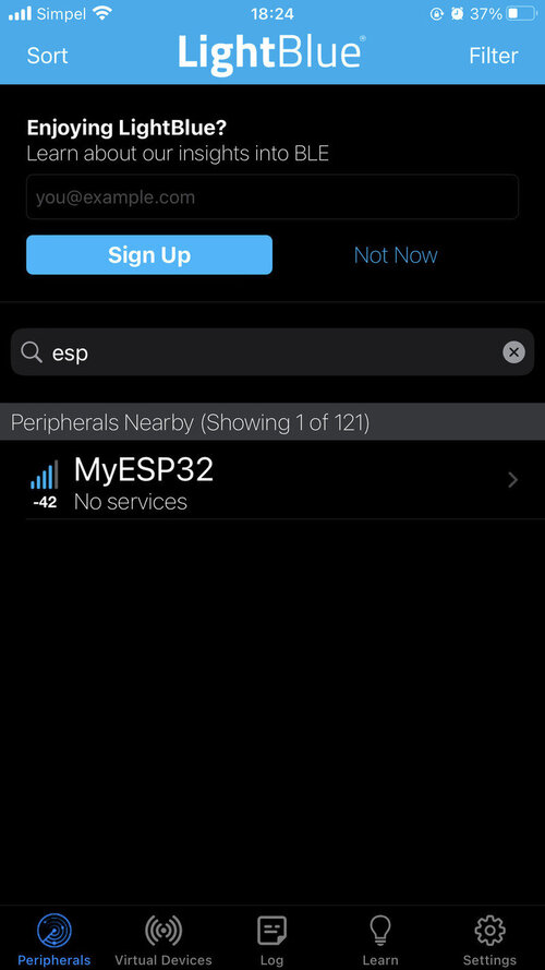
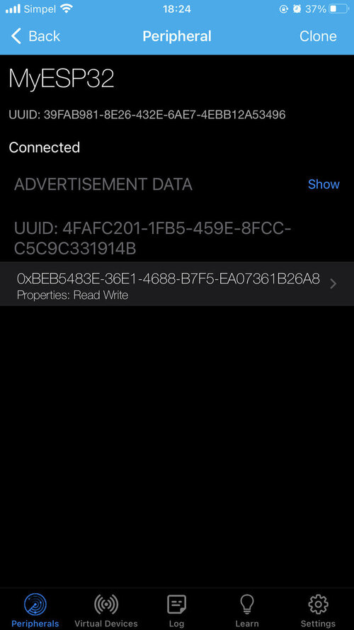
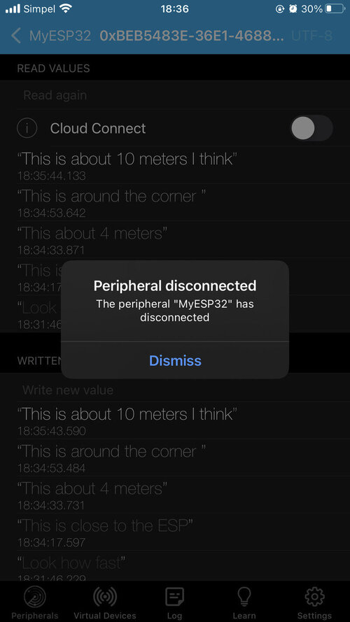
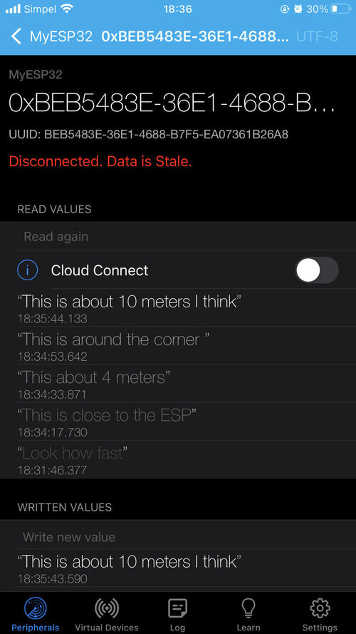
The next tutorial is using the ESP as a Bluetooth server to send strings to the serial monitor via my phone. I copied the code from the tutorial and uploaded it, and downloaded LightBlue as suggested on my iPhone 8 Plus.
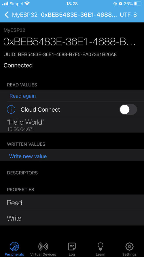
Here you can see the ESP device; if you click on it you can connect to it. You can click on the long string with Properties: Read Write under it. Then click on HEX in the top right corner to change the characteristic format. I changed it to UTF-8 String to print text to the serial monitor.

Then you can click on Write new value and type a message.

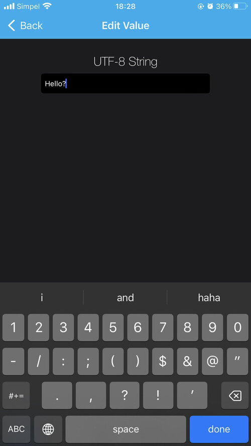

Finally something that works without too much trouble!
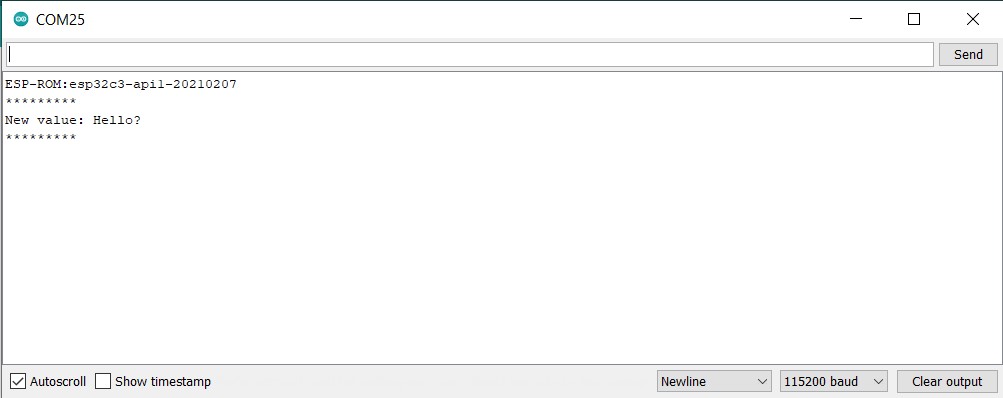
Here you can see how fast it is:
I tested the connection from different distances; when I was at about 15 meters with a wall between me and the ESP, I lost connection. 10 meters through an open door was fine. I did read here that it should have a stable connection over a distance of 100 meters, but maybe the wall was too thick, or it’s an optimistic number.

Troubleshooting
No serial output
Note: first check if you actually started the serial communication in the setup!
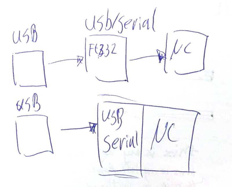
When trying to get the resolution of the various data types, I ran into a problem: I didn’t get any output on the serial monitor, although the code was uploaded successfully according to the terminal. With an Arduino Uno, this worked fine, but on the RP2040 there was nothing.
To see if the board was broken, I uploaded the Blink sketch I had before, which worked just fine. An ASCII table dump also didn’t work, so I was a bit puzzled. Luckily Bas was sitting next to me and had an idea of what it could be: the XIAO boards work differently from how the chips from previous Fabacademy years work, in that there is not a physical serial connection between the board and the computer. Instead, the serial connection is kind of integrated into the board. It is a board with a direct (native) USB port. A result of this is that Arduino tries to open the serial monitor before it is available. Bas visualized it like this:
And to quote Majenko on Stack Overflow:
When you open the serial port of a board like the Uno or Mega the whole board usually resets*, so opening the serial port allows you to see the first bits of the serial data. On the Leonardo etc it doesn’t reset when you open the serial, so any serial output during the setup() function would be missed. Adding that line makes the board pause until you open the serial port, so you get to see that initial bit of data. (via https://arduino.stackexchange.com/questions/4556/what-does-the-line-while-serial-do-in-an-arduino-program)
A workaround is to add a delay of a second or so to the setup, or to add a while (!Serial);. This means that the program waits for the serial port to connect. This second method is the better option of the two.
String str;

void setup() {
  Serial.begin(9600);
  while (!Serial) {
    ; // wait for serial port to connect. Needed for native USB port only
  }
  Serial.println(str + "size of byte: " + sizeof(byte));
  Serial.println(str + "size of int: " + sizeof(int));
  Serial.println(str + "size of long: " + sizeof(long));
  Serial.println(str + "size of float: " + sizeof(float));
  Serial.println(str + "size of double: " + sizeof(double));
  Serial.println(str + "size of int32_t: " + sizeof(int32_t));
  Serial.println(str + "size of int64_t: " + sizeof(int64_t));
  Serial.println(str + "size of String: " + sizeof(String));
}

void loop() {
}
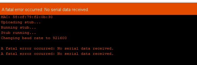
esptool
After a first succesful Blink sketch, I suddenly couldn’t upload to the ESP anymore. I kept getting this fatal error message:
I started some simple troubleshooting:
- Looking the error message up online
- Restarting computer
- Pressing reset button
- Pressing bootloader button
- Pressing both buttons together
- Connecting cable to different port
This all didn’t help, so Bas downloaded esptool for me (although I have it somewhere on my computer already, Arduino uses it to talk to the ESP) and we checked it out. Pressing bootloader and reset again suddenly did help of course, it was in the wrong mode. This happens from time to time; pressing both buttons, hoping for the best and uploading again is one workflow, but checking whether it worked is better.
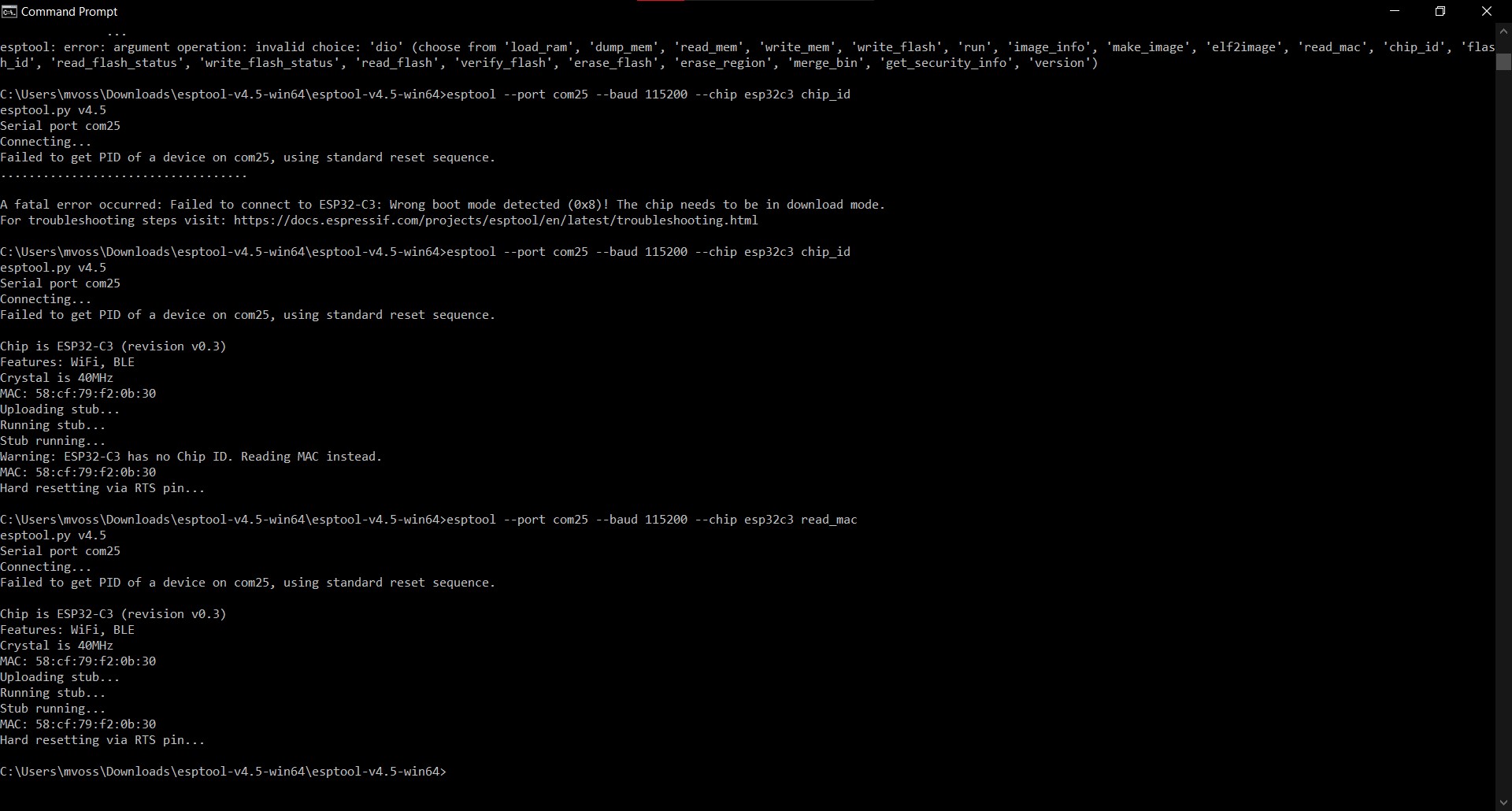
In the esptool folder run esptool --port com25 --baud 115200 --chip esp32c3 read_mac to check the connection. If you get a serial exception error, the serial monitor is probably still open in Arduino. Close it and run it again.
C:\Users\mvoss\Downloads\esptool-v4.5-win64\esptool-v4.5-win64>esptool --port com25 --baud 115200 --chip esp32c3 read_mac
esptool.py v4.5
Serial port com25
Connecting...
Failed to get PID of a device on com25, using standard reset sequence.
...............

A serial exception error occurred: ClearCommError failed (PermissionError(13, 'The device does not recognize the command.', None, 22))
Note: This error originates from pySerial. It is likely not a problem with esptool, but with the hardware connection or drivers.
For troubleshooting steps visit: https://docs.espressif.com/projects/esptool/en/latest/troubleshooting.html
If you get this fatal error, it’s in the wrong boot mode, so you have to press the bootloader and reset button together and send the same command again.
C:\Users\mvoss\Downloads\esptool-v4.5-win64\esptool-v4.5-win64>esptool --port com25 --baud 115200 --chip esp32c3 read_mac
esptool.py v4.5
Serial port com25
Connecting...
Failed to get PID of a device on com25, using standard reset sequence.
...................................

A fatal error occurred: Failed to connect to ESP32-C3: Wrong boot mode detected (0x8)! The chip needs to be in download mode.
For troubleshooting steps visit: https://docs.espressif.com/projects/esptool/en/latest/troubleshooting.html
If you get this, you’re ready to upload code again:
C:\Users\mvoss\Downloads\esptool-v4.5-win64\esptool-v4.5-win64>esptool --port com25 --baud 115200 --chip esp32c3 read_mac
esptool.py v4.5
Serial port com25
Connecting...
Failed to get PID of a device on com25, using standard reset sequence.

Chip is ESP32-C3 (revision v0.3)
Features: WiFi, BLE
Crystal is 40MHz
MAC: 58:cf:79:f2:0b:30
Uploading stub...
Running stub...
Stub running...
MAC: 58:cf:79:f2:0b:30
Hard resetting via RTS pin...
It’s really annoying to have to keep pressing the two tiny buttons almost every time you want to upload code; so far there isn’t an alternive bootloader (https://forum.seeedstudio.com/t/xiao-esp32c3-wont-upload-programs-unless-im-in-bootloader-mode/267446/9).
If nothing is happening but your code did upload succesfully, press the reset button on the board
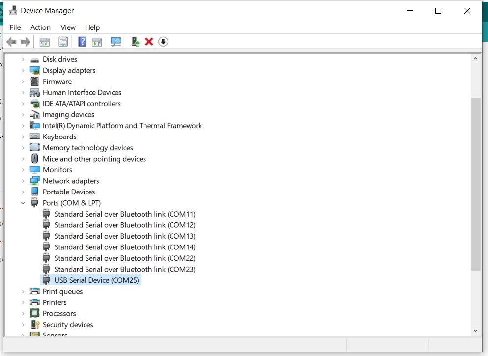
Device Manager
If you don’t know what COM port the board is connected to, you can have a look at the Device Manager (Windows) (Windows button > search for device manager). Unplug and plug back in to see which one appears.
Reading a datasheet
I decided to read through the datasheet of the ESP32-C3; the RP2040 has a 646 pages datasheet while the ESP32-C3 has only 45, and I like that the ESP32-C3 has Bluetooth and WiFi capabilities. I also hope to find out more about the reset and boot buttons because they have been very frustrating.
ESP32-C3
Notes:
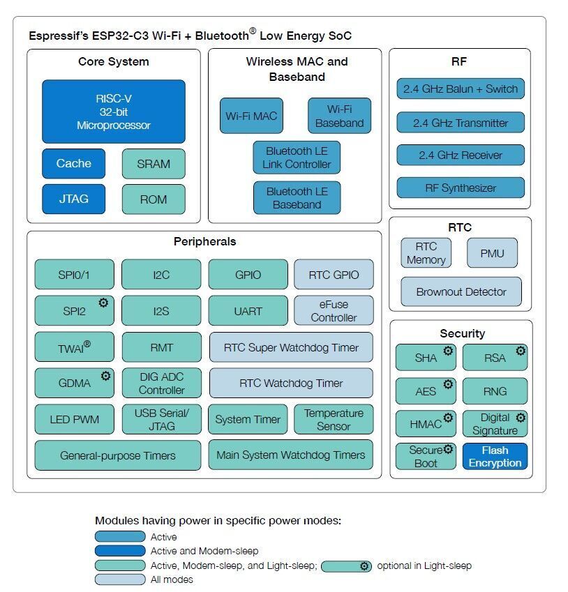
- The ESP32-C3 is ultra-lower-power
- Supports 2.4 GHz WiFi (20 MHz, 40 MHz bandwidth)
- Supports Bluetooth Low Energy (supports features of Bluetooth 5 and Bluetooth mesh)
- 32-bit RISC-V single core processor (RP2040 is dual core)
- Operates at up to 160MHz
- 400kb SRAM (16kb of which for cache)
- 384kb ROM
- You can connect external flash for more memory
Overview:
The name of the various versions of the chip is built like this:
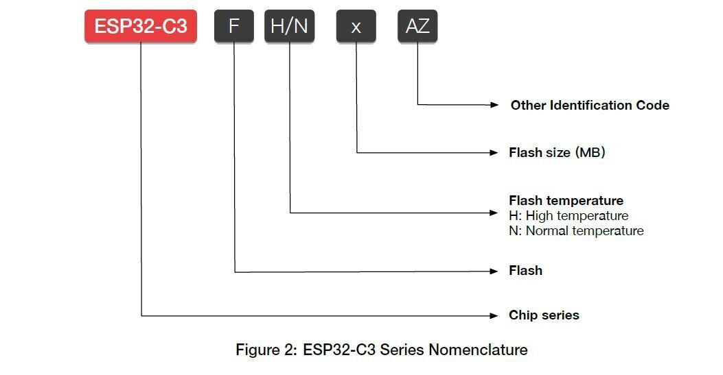
The chip on the XIAO board says that it’s the ESP32-C3, which according to the datasheet means that there is no embedded flash. On the seeed studio website it is explicitly mentioned that the ESP32-C3 has 4MB flash on the chip, while the RP2040 has 2MB flash on board (so not on the chip). I think it means that the 4MB flash on the XIAO is external SPI flash, or the chip is the ESP32-C3FH4 which has 4MB embedded flash.
This is the lay-out of the chip with descriptions of the pins:
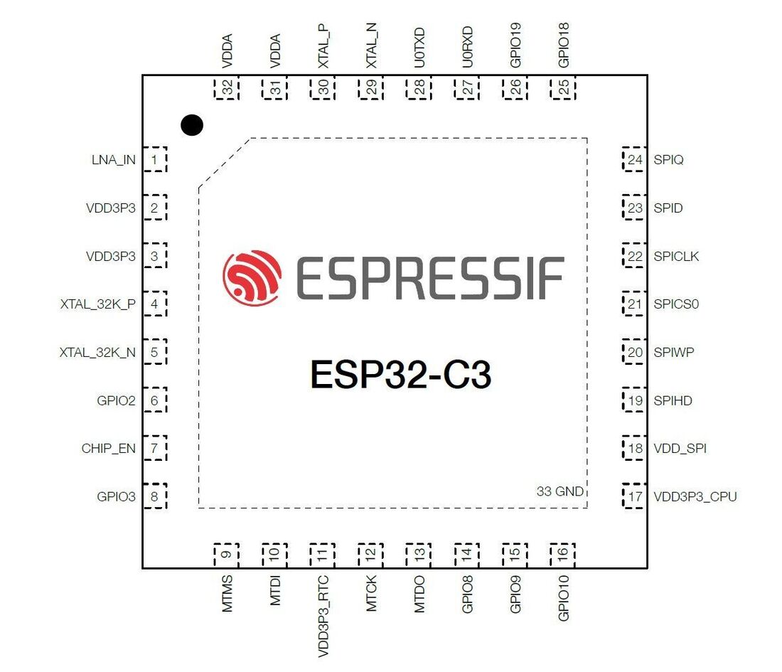

All of these acronyms don’t mean much to me, so an overview of what it means might be useful for me.
- Pa: analog power supply
- Pd: power supply for RTC IO
- I: input
- O: output
- T: high impedance
High impedance
I looked up high impedance and I found this site explaining the difference between normal pins, open collector pins and high impedance pins. High impedance pins are pins that can float between 1 and 0 if they don’t have a resistor to pull their value up (hence pull-up resistor). I’ve seen pull-up and pull-down resistors being mentioned in code before, but I mostly succesfully ignored it. On Arduino Uno there are some pins that have a build-in pull-up or pull-down resistor that you can activate by calling

- Normal pins (S1) switch between high (supply voltage) and low (ground)
- Open collector pins (S2) switch between disconnected (Hi-Z) and low (ground)
- Open collector/high impedance pins cannot output a high (1)
- A pull-up resistor (1K to 10K ohms) holds the open collector/high impedance pin high
So an example:
- With a pull-up resistor: button unpressed = logic state HIGH & button pressed = logic state LOW
- With a pull-down resistor: button pressed = logic state HIGH & button unpressed = logic state LOW
The erratic behavior of floating values can be made visible with an LED as done in this example.
Open collector buses
On the previous page I also saw something about open collector buses, which I also thought might be relevant. It’s the same as an open drain output, uses a transistor as a switch that disconnects/connects an IC output pin to ground, instead of outputting a specific voltage or current. (via https://en.wikipedia.org/wiki/Open_collector)
This is a visualization of an open collector output:
Open drain output is pulled Low when the MOSFET is conducting. In the nonconducting hi-Z state, an external resistor pulls the output High so the output’s voltage does not float.
These outputs can be used to drive higher or lower voltage devices with a chip operating at 5V, because the pull-up resistor is external and does not need to be connected to the chip supply voltage. I’ve seen this in action during Fabricademy when making a cardboard MOSFET circuit, but I didn’t know why it worked, just how to make and use it.
Strapping pins
Then there is a part about strapping pins. I found this answer on edaboard.
To assign a default state of a pin on power on or reset time. When do we use : If a logic value ‘0’ or ‘1’ is an active value of this pin, and you don’t want to be activated it on power-on or reset, you may strap it to a value that you need…
Analog peripherals
ESP32-C3 integrates two 12-bit SAR ADCs.
- ADC1 supports measurements on 5 channels, and is factory-calibrated.
- ADC2 supports measurements on 1 channel, and is not factory-calibrated.
ADC means analog/digital converter; this is a way to convert analog real world data into digital signals.

An 8-bit ADC will have a resolution of one part in 255, (28 – 1). Thus an analogue to digital converter takes an unknown continuous analogue signal and converts it into an “n”- bit binary number of 2n bits (via https://www.electronics-tutorials.ws/combination/analogue-to-digital-converter.html)
The chip also has an integrated temperature sensor: it generates a voltage that varies with temperature which is internally converted via an ADC into a digital value.The temperature sensor has a range of –40 °C to 125 °C. It is designed primarily to sense the temperature changes inside the chip.
Digital peripherals
The chip has 22 GPIO pins. These are general purpose input output pins: pins that aren’t dedicated to anything. They’re there to input or output single bits (0 or 1) (via https://www.switchdoc.com/2018/02/gpio-pins-general-purpose-input-output/). Some of these can be used for analog functions like ADC.
All GPIOs have selectable internal pull-up or pull-down, or can be set to high impedance. When these GPIOs are configured as an input, the input value can be read by software through the register. Input GPIOs can also be set to generate edge-triggered or level-triggered CPU interrupts. All digital IO pins are bi-directional, non-inverting and tristate, including input and output buffers with tristate control. These pins can be multiplexed with other functions, such as the UART, SPI, etc. For low-power operations, the GPIOs can be set to holding state.
Reflection
I spent more time looking up acronyms online than reading the datasheet, maybe that’s why it’s so short. I learned more about general electronics than about this specific chip, but I think that’s okay. I’m glad I learned about floating values, because I’ve run into issues with it I believe, but just blamed it on the circuits since I was working with e-textiles (they can be pretty unstable).
To remember:
- Floating pins have an undefined value causing irregular behavior which can be fixed with pull-up or pull-down values
Here is a comparison of all of the boards; interestingly the table mentions that ESP is not compatible with MicroPython while Pieter got it to work so maybe it’s not up to date.
Glossary
| Definition | What is it |
|---|---|
| IC | integrated circuit, a chip |
| RAM | It is a type of volatile memory as it loses data after the power is disconnected. It contains data and processes for a limited amount of time, only until the CPU requires it. (via https://www.geeksforgeeks.org/difference-between-ram-and-sram/) |
| Flash, ROM, RAM | “Flash memory combines the advantages of ROM and RAM. It not only has the electrically erasable and programmable capability (EEPROM), but also can read data quickly without power loss (the advantage of NVRAM). This memory is used in USB and MP3. For the past 20 years, embedded systems have been using ROM (EPROM) as their storage device. However, in recent years, FLASH has completely replaced the position of ROM (EPROM) in embedded systems to store Bootloader and operating systems, or Program code or directly as the hard disk (U disk).” (via https://hackernoon.com/differences-between-ram-rom-and-flash-memory-all-you-need-to-know-ghr341i) |
| SPI | Serial Peripheral Interface, standard protocol for serial communication |
| PWM pins | Pulse Width Modulation pins (indicated with ~); getting analog results with digital means. Digital control is used to create a square wave, a signal switched between on and off. This on-off pattern can simulate voltages in between the full Vcc of the board (e.g., 5 V on UNO, 3.3 V on a MKR board) and off (0 Volts) by changing the portion of the time the signal spends on versus the time that the signal spends off. The duration of “on time” is called the pulse width. To get varying analog values, you change, or modulate, that pulse width (via https://docs.arduino.cc/learn/microcontrollers/analog-output) |
| Clock speeds | Clock speed is the number of pulses that a crystal oscillator generates within a second, and processor speed is the number of cycles completed by a processor within a second. A processor should be synchronized by a clock, and therefore, processor speed is depended on clock speed. (via https://www.differencebetween.com/difference-between-clock-speed-and-vs-processor-speed/) |
| Baud rate | speed of communication over a data channel (pulses per second) (via https://en.wikipedia.org/wiki/Baud) |
What is EEPROM vs SRAM vs Flash memory https://en.wikipedia.org/wiki/EEPROM
Flash memory is a type of EEPROM designed for high speed and high density, at the expense of large erase blocks (typically 512 bytes or larger) and limited number of write cycles (often 10,000).
SPI:
- SCLK: Serial Clock (output from master)
- MOSI: Master Out Slave In (data output from master)
- MISO: Master In Slave Out (data output from slave)
- CS /SS: Chip/Slave Select (often active low, output from master to indicate that data is being sent)

Python is an interpreter and if you upload code, the code stays in Python and Python is also on the chip, it’s not compiled before you upload it. Python runs the script on the chip so the python interpreter is a compiled program/executable file C/Arduino is code that has to be compiled before it is being sent to the processor, it’s a ready to go executable file. It’s turned into a binary.
Notes
- We’re going to use the XIAO boards this year for the first time
- Architecture: we’re going to use the Harvard
- RISC (instead of CISC) this week
- Microcontroller is a both simpler and more advanced than a microcontroller; simpler because it has both a processor and it has built-in communication and other things
- GPU for larger projects (not this week)
- Pulse Width Modulation (PWM): important
- Peripherals
- Lower frequency means its slower
- 8 bit processors can do 32 bit operations, it just takes a couple of cycles
- ATTiny 10 is smallest (in Fabacademy), size of a grain of rice
- AVR
- ATTiny families
- ARM
- SAMD11C
- RP2040 (Raspberry Pi); this is on one of the two XIAO boards (castellated board)
- RISC-V (this is going to take over the world according to Neil)
- ESP32-C3; this is the other XIAO boards (same pin-out)
- ATTiny vs ARM: ARM runs at lower voltage and faster clocks, more powerful peripherals (roughly), but the architecture is much more general; wide range in the family
-
XIAO board is a complete system, you can integrate it into all kinds of projects
- We’re going to use C to program
- Start from an existing program and modify it
-
GCC transforms your code into code that the processor understands
- Microchip Studio for Windows for AVR and SAMDI
- Rust or Go can be used instead of C (memory leaks and memory overruns can make it possible data to be stolen, race conditions)
- This week you can work in C (Arduino is C with libraries) or Python
MicroPython:
- Interpreting is way more direct; compiled code is way faster
- MicroPython can do both, so you can use it for realtime things
In-system development: how you load code into it
- AVR
- ISP (original AVR, kind of obsolete)
- UPDI (newer)
- ARM
- JTAG SWD
IDE (integrated development environments)
- Arduino and PlatformIO in VSC are the ones I’ve used before
- Cores install the whole toolchain for you in Arduino
Operating systems:
- Bare-metal: just your program
-
Multitasking: multiple programs doing different things on one processor
- Embedded debugging with GDB
AI
- ChatGPT or Copilot code can be used but you have to attribute (to both humans and machines)
- Often the code has bugs in it so you need to review it
- They can make stuff up and they can steal from copyrighted code and not add the correct licenses