Machine building week
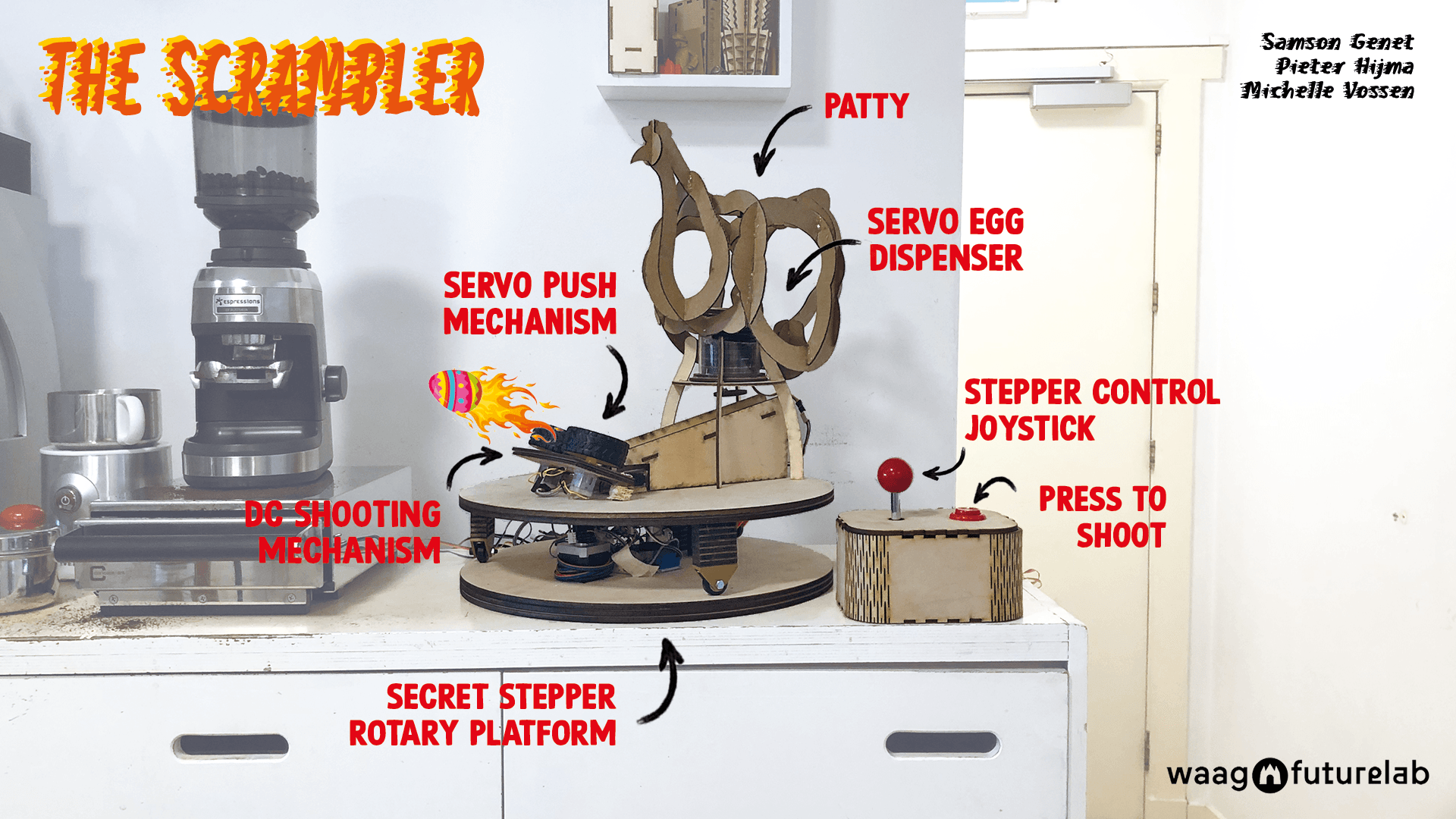
Easter Egg Shooter: the Scrambler
Slide
Video
What does it do?
The Scrambler keeps you focused and concentrated because it provides you with unwrapped chocolate Easter eggs without the hassle of standing up. The incredible innovative design makes use of a joystick and button that are both incredibly important. The joystick controls the platform so you can shoot in the correct direction. The push button activates the egg dispenser, egg pusher and shooting mechanism. The Scrambler is THE machine you can't miss during a week full of work and chocolate Easter eggs.
How does it work?
- Rotate the Scrambler clockwise and counterclockwise with the joystick to aim
- Press the big red button to initiate the system
- The two DC motor wheels start spinning in opposite direction
- The micro servo door dispenses one egg from the chicken reservoir
- The egg rolls down the slide
- At the bottom of the slide, another servo motor pushes the egg towards the spinning wheels
- The egg gets launched with great force to our table! If you're lucky it gets unwrapped in the process.
Why do we need it?
Machine week started 1.5 weeks before the Easter weekend. The Waag was filled with delicous colorful easter eggs. We came to the conclusion that we would be too busy this week to stand up and leave our desk to get an Easter chocolate egg. So it was obvious to us that we needed to solve this problem, and design a machine that would help us out and ensure us with unwrapped Easter eggs without the time-consuming task of getting up. And BAMM, the Scrambler was born!
Who made it?
Samson Genet, Pieter Hijma and Michelle Vossen. The links to everyone's individual documentation pages can be found here:
Process
Thursday March 30
On Thursday morning after Saco's lecture we started by checking everyones availability in the coming two weeks since our calendars are quite a 'gatenkaas' (cheese with holes) as we call it in Dutch. After that we started a brainstorm session. Inspired by the bowl of Easter chocolate eggs and Pieter's frustration that he has to get up to grab some chocolate instead of it coming to him automatically, Samson's passion for animatronics and Michelle's love for chicken, we quickly decided on a chicken ornithopter that can lay chocolate eggs.
Our first goal is to make it fly, and to be able to control its flight, so that is our primary focus. Since there is a pretty good chance that it's going to be trickier than we hope, we have some back-up ideas to bring our chicken to life. Some possible spirals:
- Flying/flapping for short distances (like a real chicken)
- Walking (think Theo Jansen's strandbeesten)
- Bopping its head
- Screaming chicken sounds
- Laying chocolate Easter eggs
We gave ourselves the deadline of Tuesday the 4th at the end of the day to make our chicken fly. We divided some tasks and got to work. Pieter dove into batteries and DC motors suitable for flight, Samson looked into gears and Michelle made a first ornithopter prototype in Fusion. Ella and Maria, the fablab interns, did research on the crank mechanism to make the wings fly simultaneously.
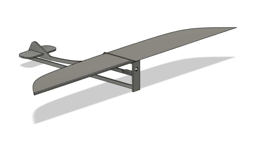
This is the assembled prototype; the crank mechanism is not attached to the wings because the motor and wings are too close together.
As a reflection on the first day: we kind of all started like chicken without a head after dividing the tasks. We didn't make a sketch and no one really knew what the other was doing, so that wasn't very productive. We also didn't discuss our progress and made a plan for the next days together, so it was a bit chaotic.
Friday March 31
On Friday it was just Michelle in the fablab together with the interns and Saco. She worked on the body of the chicken and a mechanical design with a new gear system the whole day.
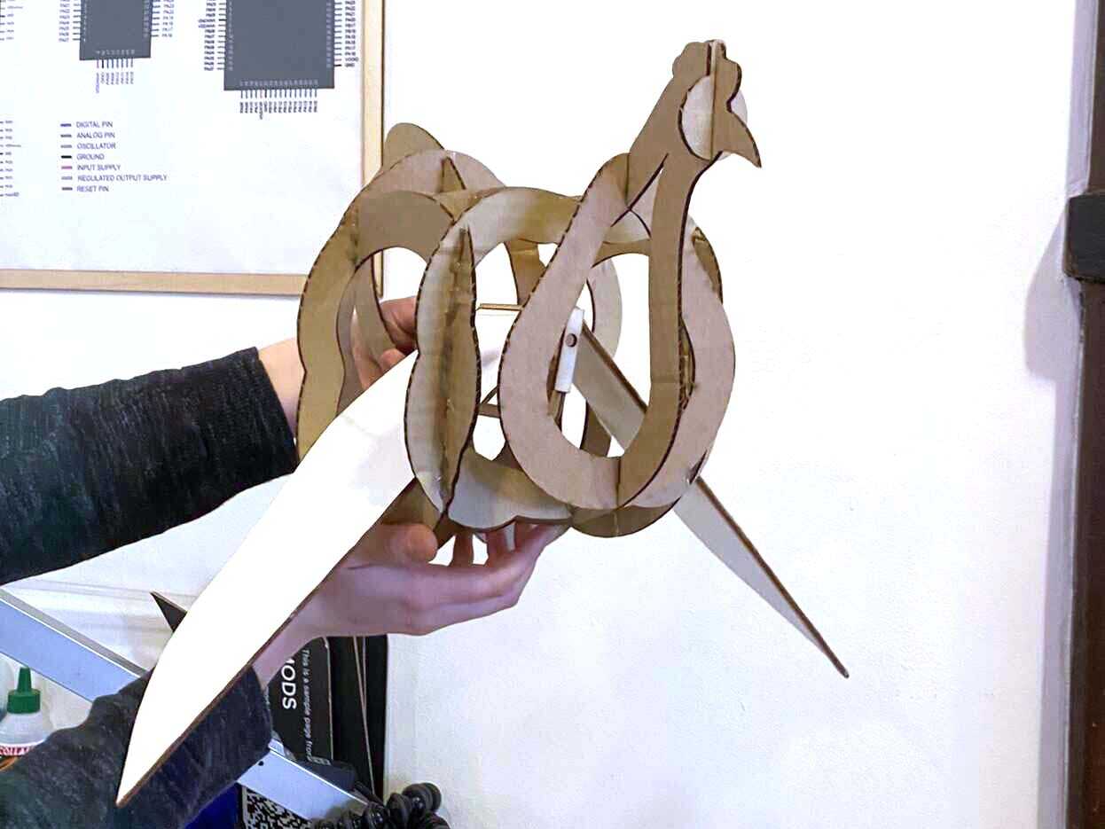
Chicken prototype
To make the body of the chicken, Michelle used this 3D model of a chicken from Thingiverse. Then the chicken was turned into 2D slices with Slicer for Fusion360 with interlocked slices. Some of the slices are moved around so there's enough space for wings to flap freely.
Single gear crank mechanism
We decided against the staggered crank mechanism that we had on Thursday, because it didn't work yet and didn't feel reliable and stable. Samson found this example of a simple flapping mechanism with a bunch of gears:
Saco helped with simplifying the gear mechanism: there are four gears and they transfer the motion from motor gear to bottom gear, bottom gear to right wing gear, and right wing gear to left wing gear, so a lot of motion transfer. Saco advised to only use the gear on the motor and the bottom to make it simpler. What it comes down to then is to make a single gear crank. More on the process to make the gear mechanism can be found on Michelle's documentation page.
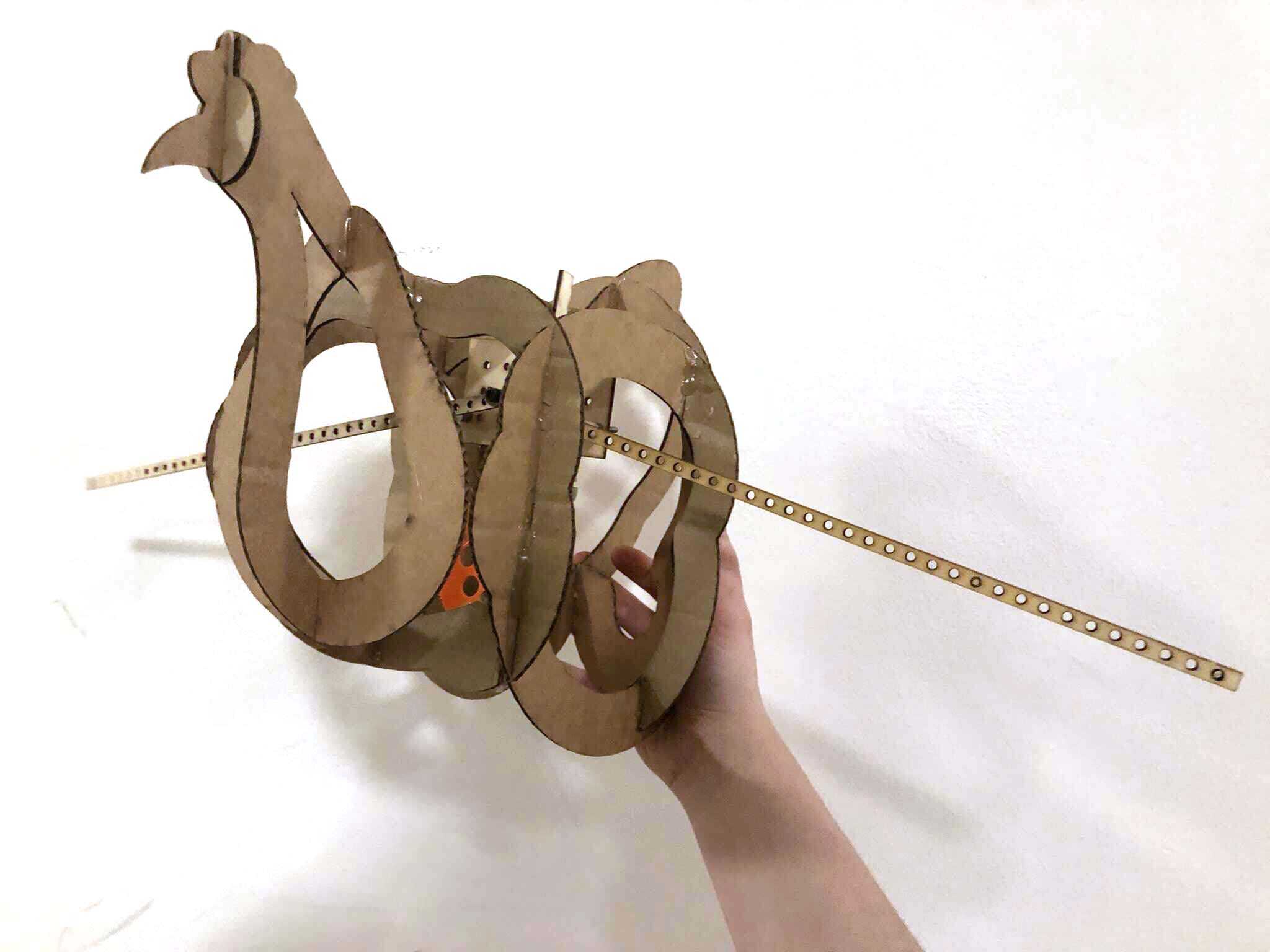
After a couple of iterations there was a working single crank mechanism, although it still needed some improvements. It was still quite wobbly because the distances have to be improved between the gears. The distance between the big gear and small gear is a little too much, and you can see it's still a little wobbly. The mechanism works because there is some play possible between the crank and the two wings; otherwise the mechanism would be completely stuck because of Pythagoras' theorem.
The mechanism fits in the chicken; here it's taped to the cardboard frame.
Monday April 3
On Monday it was just Pieter in the lab together with Maria and Henk. Pieter worked on a new mechanical design entirely because he thought there was too much play in the current mechanism. Maria worked on a wing design based on actual chicken wings.
Today we ran into the problem that not everyone uses the same programs: Michelle, Samson and the interns use mostly Fusion360 to design because it's provided during the Fabacademy while Pieter uses FreeCAD because it's open source. This makes it harder to work together on files (or actually impossible). Maria worked from Michelle's file while Pieter made something in FreeCAD. The gears were made in OpenSCAD so that was easier to share.
Pieter started on a new gear mechanism:

Tuesday April 4
On Tuesday we were finally together with the whole group again. Today we really learned the importance of communication when working in a group. We discussed the problems we had and divided tasks again. Samson looked into materials suitable for the wings and how to connect them to the wing frames. Michelle and Pieter both had a different vision of the gear system so they ended up both continuing to work on their own gear mechanisms. In hindsight, this is the opposite of working together. Both mechanisms worked somewhat, but just not good enough for flight, and frustration was building up. We didn't have a clear vision of what we were doing and we were just continuing stubbornly with what we wanted but weren't sure was going to work.
Michelle's gears were somewhat working but the motor had to work really hard because there was too much resistance, even with a bearing. It was really easy to stop the motor with your finger, so it wouldn't be enough torque to make a wing flap let alone flap fast enough for flight.
Pieter continued his gears but also didn't manage to finish in time:

Change of plans
Since we had our deadline today to get an actual flying ornithopter, and we were nowhere close to something flying, we had to give ourselves an intervention. At 15:30 we sat down together with Henk to discuss what to do. We were all tired and frustrated, and the project wasn't fun at all anymore. The weight budget and battery troubles turned it into a really complicated and technical project, and we are all no mechanical engineers. To put it simply, we likely don't have the time and skill to make it work well, and it's distracting us from actually working together on something cool. Henk said what we were doing is way too complicated and is skeptical too.
At this point we could decide to continue, or we could start over. The only thing that would be lost if we wouldn't make an ornithopter is the flying mechanism research we have done, but it hasn't really gotten us into flight yet. We decided to start over and head back to the drawing table. One of the other ideas we had on Thursday was an Easter Egg shooting machine. This is a machine that would allow us to work more in spirals and to divide tasks easily. We (finally) made a sketch together:
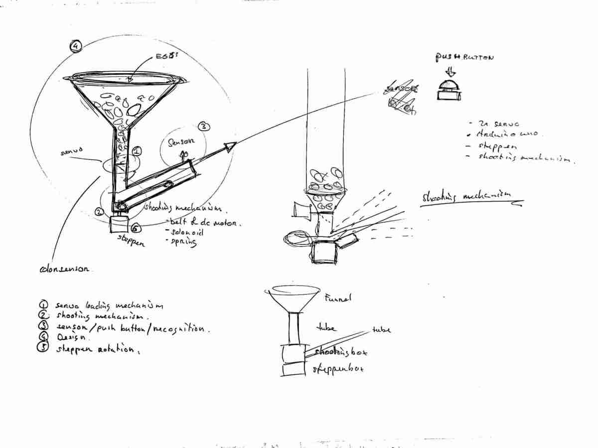
We divided the tasks for Tuesday and Wednesday like this: - Samson worked on the shooting mechanism with DC motors - Michelle worked on an egg dispenser with a servo motor - Pieter worked on the rotating platform with a stepper motor
We had all kinds of wild ideas to control the shooting of the eggs, but Henk warned us to work in spirals, and to not make it super complicated right away again. So we decided to first make the machine work with buttons, and see if we can use different sensors (like actuating it by waving at it with an ultrasonic sensors) or Bluetooth after we have a working machine.
We agreed to involve each other more in the things we were working on, and to have a mini-meeting every hour or so to discuss our progress and make sure we would be on the same page.
At the end of the day, Samson had a first powerbench powered prototype of the shooting mechanism:
Pieter was busy with stepper motor control:
And Michelle had a first mechanical prototype for the egg dispenser:
Wednesday April 5
The next day, we were all together again. Pieter tested positive for COVID and Michelle had a worsening cold, but we continued working (there are no COVID restrictions in the Netherlands anymore, it's treated like any other endemic virus now). We all continued working on our respective tasks.
Samson mounted the DC motors and ramp on a heavy piece of wood and Michelle made a tube to put the eggs in that will dispense eggs at the bottom with a servo motor. Here you can see them together:
The eggs only got shot when they received a little push. You can see the issue clearly here:
Pieter proposed a servo that pushes it, so Samson integrated a pushing servo into the next iteration.
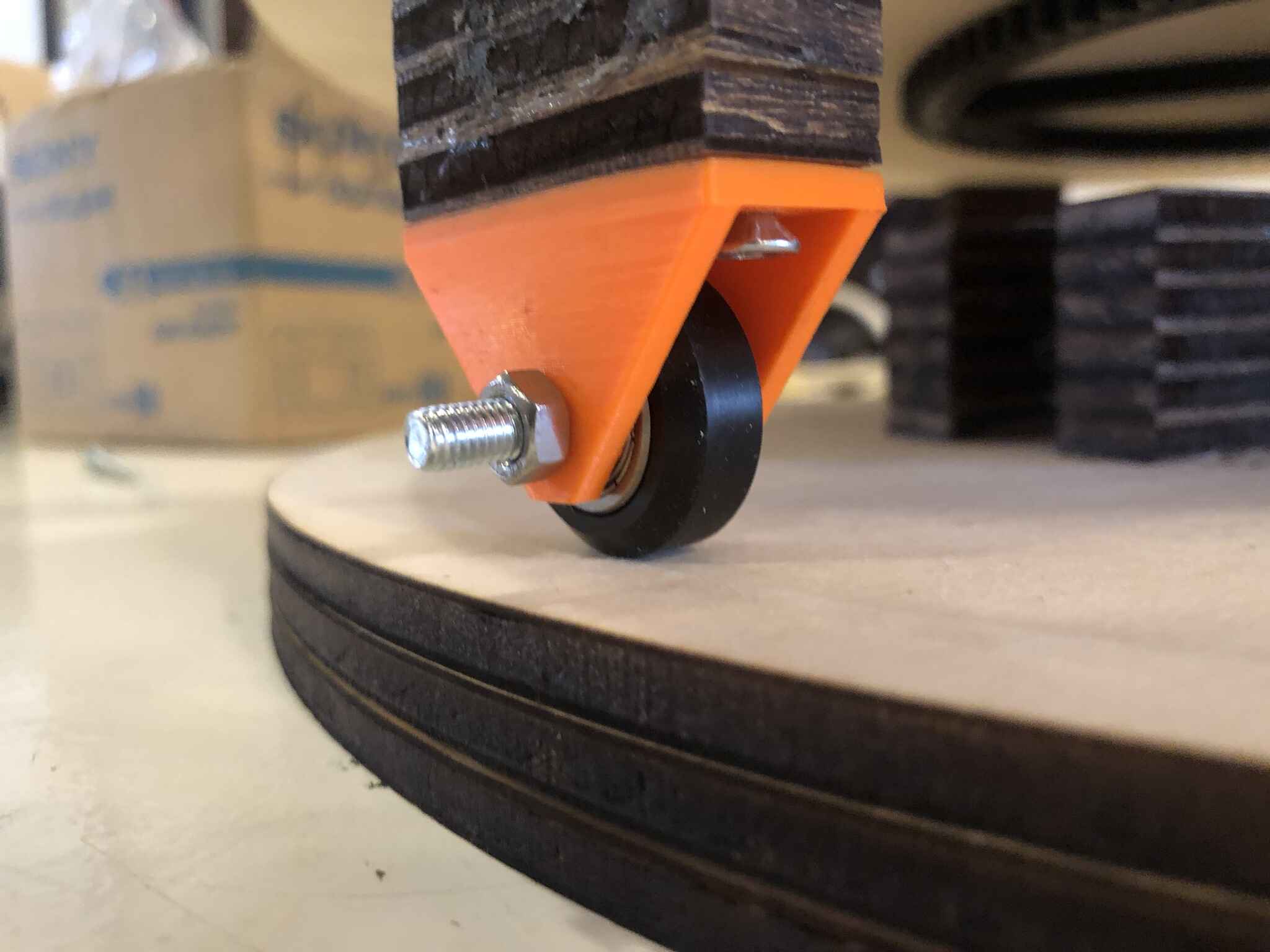
Pieter was focusing on the round table, looking for mechanisms to drive the platform. He designed and 3D printed bearing wheel holders for the platform.
The egg dispenser servo that Michelle was working on attached to an Arduino Mini Pro opens and closes just fine, however the eggs easily find equilibrium above the dispensing hole. When they are all balanced, no eggs come out.
After multiple iterations the next attempt was a bunch of donut shaped spacers and stacked them together. What this does is basically just moving the problem up, but as long as there are eggs in the 'tube' it's dispensings eggs pretty OK. Here you can see it working:
The next step was to add a button to the dispenser, so we would have a trigger to start the system; it had to be recalibrated plenty of times.
Samson's and Michelle's system working together:
Then after this the servo for the egg dispenser broke, so that part had to be redone.
Thursday April 6
We were all in the lab again today. Pieter wanted to mill a board with the motor inside and a gear but Henk called it a stupid system because it puts a lot of strain on the motor when you connect it directly to the platform. He suggested an adaptation of the Urumbu system with fishing lines and windings to make the load on the motor lighter, so Pieter worked on that (read more on the process here).
Pieter also started working on Bluetooth communication between two ESP32C3 boards, our next spiral to operate the board from the table we all work together at. Michelle wanted to make a really long cable between the button box and the canon but Henk said it really was not our priority and a waste of materials.
Michelle worked on the integration of all separate motors into one system, using an Arduino Mini Pro and a breadboard, and on powering the individual parts separate from a power bench.
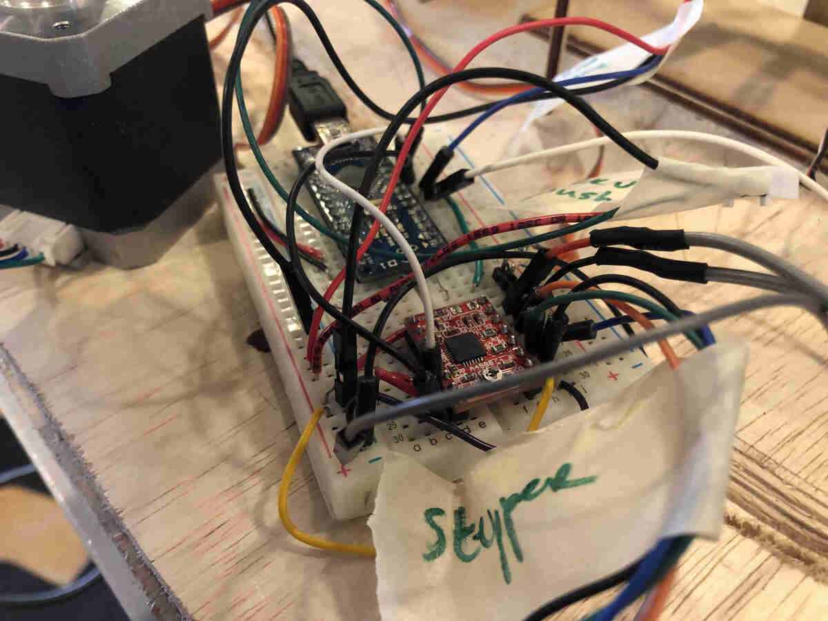
The stepper motor and DC motors are powered by a 12V power supply and the Arduino board plus servos are powered by the computer. We also integrated a joystick to be able to rotate the future stepper platform in whatever direction you want. Here you can see the entire system working together. It's a bit messy, but it's a machine!
This is the code used:
#include <Servo.h>

int servoPin = 6;
int servoPos = 0;
int servoPin2 = 10;
int pos = 0;
Servo myServo1;
Servo myServo2;

int dcPin = 5;

int inputPin = 7;  // input pin for pushbutton

#define dirPin 8
#define stepPin 9

int leftPin = 16;
int rightPin = 15;
int upPin = 14;
int downPin = 17;

int leftValue = 0;
int rightValue = 0;
int upValue = 0;
int downValue = 0;


void setup() {
  // put your setup code here, to run once:
  Serial.begin(9600);
  myServo1.attach(servoPin);
  myServo2.attach(servoPin2);
  pinMode(inputPin, INPUT);  //declare pushbutton as input
  pinMode(stepPin, OUTPUT);
  pinMode(dirPin, OUTPUT);
  pinMode(leftPin, INPUT_PULLUP);
  pinMode(rightPin, INPUT_PULLUP);
  pinMode(upPin, INPUT_PULLUP);
  pinMode(downPin, INPUT_PULLUP);
  pinMode(dcPin, OUTPUT);

}
void loop() {
  // put your main code here, to run repeatedly:
  int val = digitalRead(inputPin);  //read input value
  if (val == HIGH)   { //check for input is HIGH
    digitalWrite(dcPin, HIGH);   // turn the RELAY on
    delay(3000);                     // wait for a second

    for (servoPos = 115; servoPos >= 30; servoPos--) {
      myServo1.write(servoPos);
      delay(3);
    }
    for (servoPos = 30; servoPos <= 115; servoPos++) {
      myServo1.write(servoPos);
      delay(3);
    }
    delay(20);

    for (pos = 0; pos <= 120; pos += 1) { // goes from 0 degrees to 180 degrees
      // in steps of 1 degree
      myServo2.write(pos);              // tell servo to go to position in variable 'pos'
      delay(50);                       // waits 15ms for the servo to reach the position
    }

    for (pos = 120; pos >= 0; pos -= 1) { // goes from 180 degrees to 0 degrees
      myServo2.write(pos);              // tell servo to go to position in variable 'pos'
      delay(15);                       // waits 15ms for the servo to reach the position
    }
  }
  digitalWrite(dcPin, LOW);    // turn the RELAY off

  leftValue = digitalRead(leftPin);
  rightValue = digitalRead(rightPin);
  upValue = digitalRead(upPin);
  downValue = digitalRead(downPin);

  Serial.println(leftValue);
  Serial.println(rightValue);
  Serial.println(upValue);
  Serial.println(downValue);


  if (leftValue ==  LOW) {
    digitalWrite(dirPin, HIGH); // Enables the motor to move in a particular direction

    digitalWrite(stepPin, HIGH);
    delayMicroseconds(700);    // by changing this time delay between the steps we can change the rotation speed
    digitalWrite(stepPin, LOW);
    delayMicroseconds(700);
  }
  if (rightValue ==  LOW) {
    digitalWrite(dirPin, LOW); //Changes the rotations direction
    // Makes 400 pulses for making two full cycle rotation
    digitalWrite(stepPin, HIGH);
    delayMicroseconds(500);
    digitalWrite(stepPin, LOW);
    delayMicroseconds(500);
  }
}
As you can see in the video the DC motors have to run for a bit longer because they shut off before launching the egg. We tried to add a delay before shutting it off, but that actually made the entire system not work anymore (it took a while before we figured out that the delay was the problem).
Friday April 7
Today it was just Samson, Pieter and Henk in the lab. First we had a lot of faith in the progress we would make this day, not only because it was a holy Friday but also because we had only one goal and that was making the rotating platform work with an existing principle by Quentin Bolsee.
To start the day with a good feeling we wanted to run the machine. But unfortunately it didn't work. There was a problem with the egg dispenser and the shooting mechanism.
The shooting mechanism was a easy solve. The cables were connected in the wrong order. So after a little soldering it worked fine again.
The servo took us not too long either. The servo wasn't positioned in its start or end position. So we uploaded a simple servo code, and disassembled the arm. We attached the arm in the correct position and now we could update the code. The servo starts at 0 degrees and ends at 92 degrees. We did a couple of test to set the timing right and after a while we got it right.
Now it was time to fix the rotary platform. But after a lot of trial and error. We had to conclude that the system didn't work because the tension was too loose beacause of the play in the middle axle.
After all the hassle Pieter designed a very simple gear mechanism that worked instantly! Patty is working beautifully now!
Monday April 10
It was Easter Monday so we didn't come in to the lab. Michelle set up the group documentation page.
Tuesday April 11
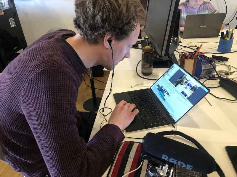
Today it was Michelle and Pieter in the lab. Pieter finished the platform and then started editing the video. We shot some videos and looked at all of our documentation videos so far to get an overview of the process.
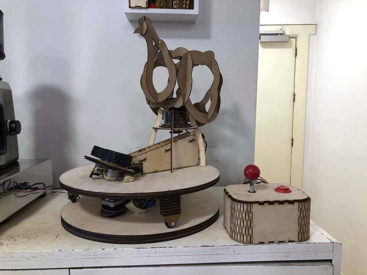
Michelle worked on bringing the parts of the machine together and making the machine look good. We replaced the cardboard slide with a plywood one and called it the 'legbatterij', which is Dutch for battery cage. The international title of our machine is the Scrambler.

Cables are hidden in the control box and between the rotating and stationary platform.
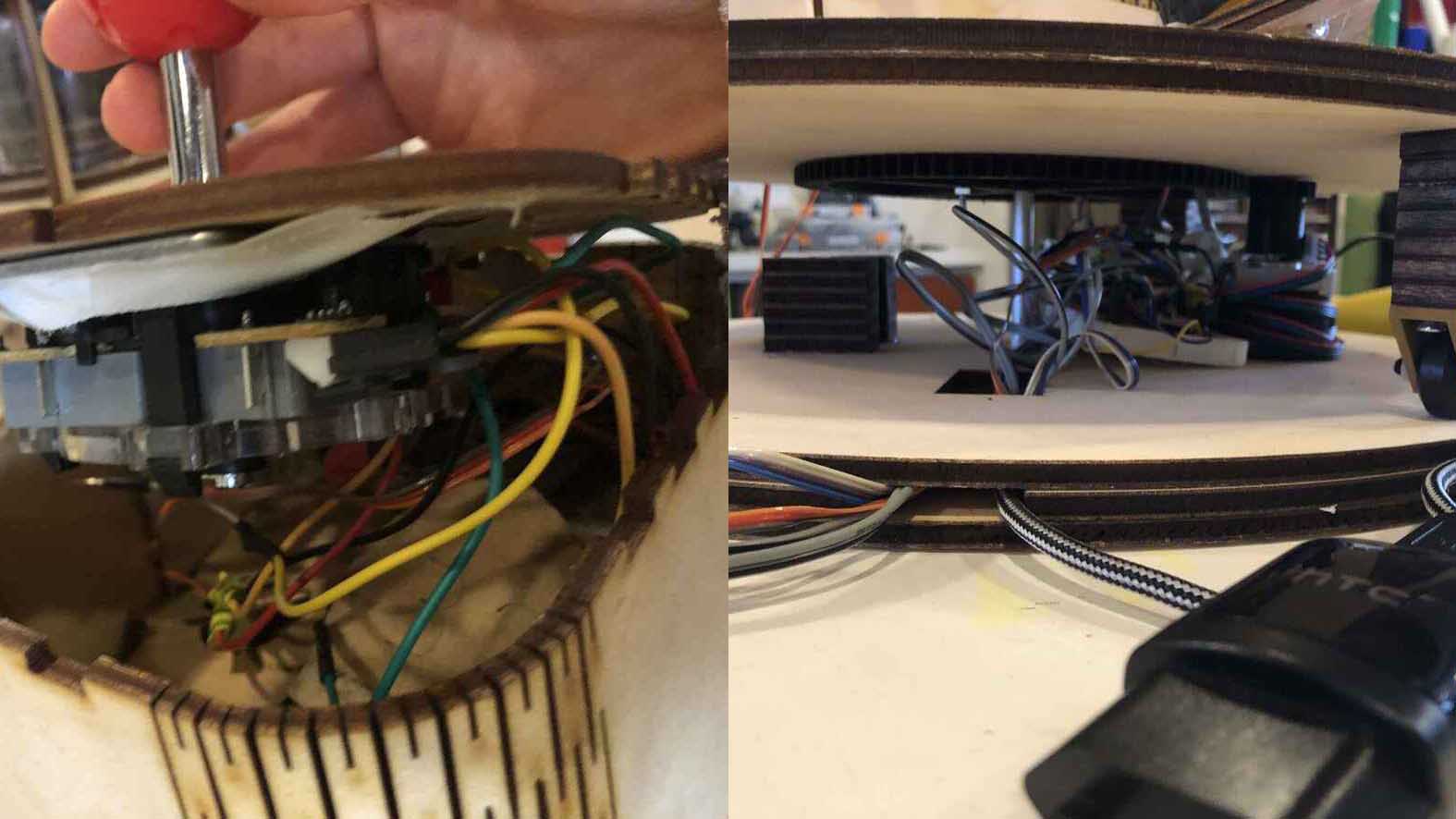
Testing the assembly:
Wednesday April 12
All together at the lab again, we shot the videos of our machine working (after some minor tweaking of the code) in between the morning rush for the coffee machine. Then Samson worked on the poster, Pieter on the video and Michelle on the group documentation. The result of this you've already seen at the top of the page.
We called our chicken Patty. Here she is at her new home in the coffee corner.
Future development possibilities
Like every living creature Patty is PERFECT! But at the Waag we always strive for more perfection. So here's a list of a few things we would like to innovate:
- The shooting mechanism can change in the horizontal direction but not in the vertical. We would like to add a servo that could higher or lower the shooting direction.
- The egg dispense mechanism is not always working. Sometimes two or even three eggs slip through the dispenser. A different design for this dispenser would come in handy, we would get to fat otherwise. We're thinking of a flapping hatch.
- The eggs roll downwards too fast. The angle of the slide should be less steep.
- Pieter figured out how to use bluetooth communication between two ESP Xiao boards. Next time we would like to control Patty wireless.
Code
#include <Servo.h>

/* We have two DC motors attached to wheels that will launch the easter eggs.

    We will call them the launcher DCs. There is a relay, the launcher_relay
    that turns the motors on. *
    We have two Servo motors, one dispensing an easter egg and one to push the
    egg into the wheels. Let's call the first one the dispense servo and the
    other one the push servo. *
    Finally, there is a turntable that rotates left or right. */

#define LAUNCHER_RELAY 5

#define LAUNCHER_DC_DELAY 3000

#define LAUNCH_PIN 7

#define DISPENSE_SERVO_PIN 6

#define DISPENSE_DELAY 3 // milliseconds

#define EGG_ROLL_DELAY 20 // milliseconds

#define DISPENSE_START_POS 0

#define DISPENSE_END_POS 92

#define PUSH_SERVO_PIN 10

#define PUSH_DELAY 50 // milliseconds

#define MOVE_BACK_DELAY 15 // milliseconds

#define PUSH_START_POS 0

#define PUSH_END_POS 120

#define UP_PIN 14

#define RIGHT_PIN 15

#define LEFT_PIN 16

#define DOWN_PIN 17

#define DIRECTION_PIN 8

#define ROTATE_PIN 9

#define STEPPER_DELAY 700 // microseconds

Servo dispenseServo;
Servo pushServo;

void setup() {
  // put your setup code here, to run once:
  Serial.begin(9600);
// set up the servos

  dispenseServo.attach(DISPENSE_SERVO_PIN);
  dispenseServo.write(DISPENSE_START_POS);
  pushServo.attach(PUSH_SERVO_PIN);
  pushServo.write(PUSH_START_POS);

  pinMode(LAUNCH_PIN, INPUT);  //declare pushbutton as input

  pinMode(LEFT_PIN, INPUT_PULLUP);
  pinMode(RIGHT_PIN, INPUT_PULLUP);
  pinMode(UP_PIN, INPUT_PULLUP);
  pinMode(DOWN_PIN, INPUT_PULLUP);

  pinMode(LAUNCHER_RELAY, OUTPUT);
pinMode(DIRECTION_PIN, OUTPUT);
pinMode(ROTATE_PIN, OUTPUT);

  //digitalWrite(LAUNCHER_RELAY, HIGH);
}

void dispenseEgg() {
    for (int pos = DISPENSE_START_POS; pos <= DISPENSE_END_POS; pos++) {
        dispenseServo.write(pos);
        delay(DISPENSE_DELAY);
    }
    for (int pos = DISPENSE_END_POS; pos >= DISPENSE_START_POS; pos--) {
        dispenseServo.write(pos);
        delay(DISPENSE_DELAY);
    }
    delay(EGG_ROLL_DELAY);
}

void pushEgg() {
    for (int pos = PUSH_START_POS; pos <= PUSH_END_POS; pos += 1) {
        // goes from PUSH_START_POS degrees to PUSH_END_POS degrees
        // in steps of 1 degree
        pushServo.write(pos);
        delay(PUSH_DELAY);
    }
for (int pos = PUSH_END_POS; pos >= PUSH_START_POS; pos -= 1) {
    pushServo.write(pos);
    delay(MOVE_BACK_DELAY);
}

}

void loop() {
  if (digitalRead(LAUNCH_PIN) == HIGH) { // we are launching an egg
    digitalWrite(LAUNCHER_RELAY, HIGH);
    delay(LAUNCHER_DC_DELAY); // wait a bit to the DCs are up to speed
    dispenseEgg();

    pushEgg();
delay(5000);

  }
  digitalWrite(LAUNCHER_RELAY, LOW);

  int leftVal = digitalRead(LEFT_PIN);
  int rightVal = digitalRead(RIGHT_PIN);
  int upVal = digitalRead(UP_PIN);
  int downVal = digitalRead(DOWN_PIN);

  Serial.println(leftVal);
  Serial.println(rightVal);
  Serial.println(upVal);
  Serial.println(downVal);

  if (leftVal ==  LOW) {
    digitalWrite(DIRECTION_PIN, HIGH); // Enables the motor to move in a particular direction
digitalWrite(ROTATE_PIN, HIGH);
delayMicroseconds(STEPPER_DELAY);
digitalWrite(ROTATE_PIN, LOW);
delayMicroseconds(STEPPER_DELAY);

  }

  if (rightVal == LOW) {
    digitalWrite(DIRECTION_PIN, LOW);
    digitalWrite(ROTATE_PIN, HIGH);
    delayMicroseconds(STEPPER_DELAY);
    digitalWrite(ROTATE_PIN, LOW);
    delayMicroseconds(STEPPER_DELAY);
  }
}