Brainstorm
This week is one large group assignment with its own Group assignment documentation . Michelle, Samson, and I are assisted by Ella and Maria. Since we have some holidays coming up we made a simple schedule of when everybody is available.
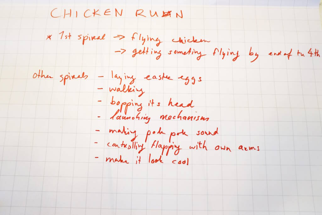
We had a brief brainstorming session that converged to an ornithopter, a flying helicopter with flapping wings. We analyzed how to do this in spirals and we concluded that we first focus on making the device fly. Since we anticipate that we won't succeed in making that happen, we decided to go mimick a chicken because they cannot fly well either.
Additionally, since we have a bowl with chocolate easter eggs, we can make the chicken lay eggs as well. We anticipate that we can't make it work, so to be safe, we came up with different directions, such as an egg dispencer, the head of the chicken bobbing, etc. We will decide on Tuesday if we can make the flying work and what we're going to focus on as alternatives.
Below a picture of our ideas, directions/spirals:
Ornithopter Approach
We first individually came up with resources to follow an existing example. We basically all found the same resources but Samson had the most concrete idea, namely to first follow the following tutorial and make the mechanical design first.
On the Ornithopter Society page, we found a Design Manual that gave us some bounds to take into account. On this page we learned that we should ideally strive for about 100 W per kg from the motor, but that 10 to 50 W per kg is also possible. We used 50 W per kg as a number to strive for.
Establishing Motor Power
Determining the power output of the motor gives us a weight budget to design the chicken. We had many DC motors available but it was difficult to find the right specs. First I tested the smallest DC motor, which is a type 130 DC motor.
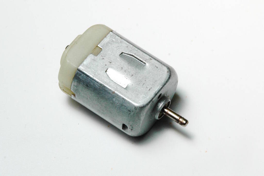
There are no markings on the body, so I assumed what I found on most websites is what we have, which uses a rated voltage of 6 V. The Adafruit website listed a maximum current of 250 mA and a stall current of 500 mA. However, if I connect it to a power source, it draws more current and I have a voltage drop. Let's stick to these numbers which means that the power of this motor is P = V * I = 6 V * 0.5 A = 3 W. This means that we have 3 W / 50 W / kg * 1000 = 30 g for a weight budget.
For the motor below, we kind-of have the datasheet:
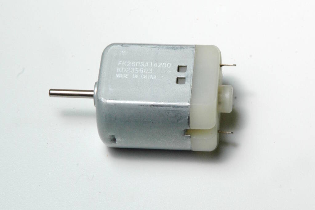
.
The numbers in the data sheet are not matching the numbers on the motor (14280), but it is most likely a 12 V motor. Attaching it to a power source, we measure a current of 1.3 A:
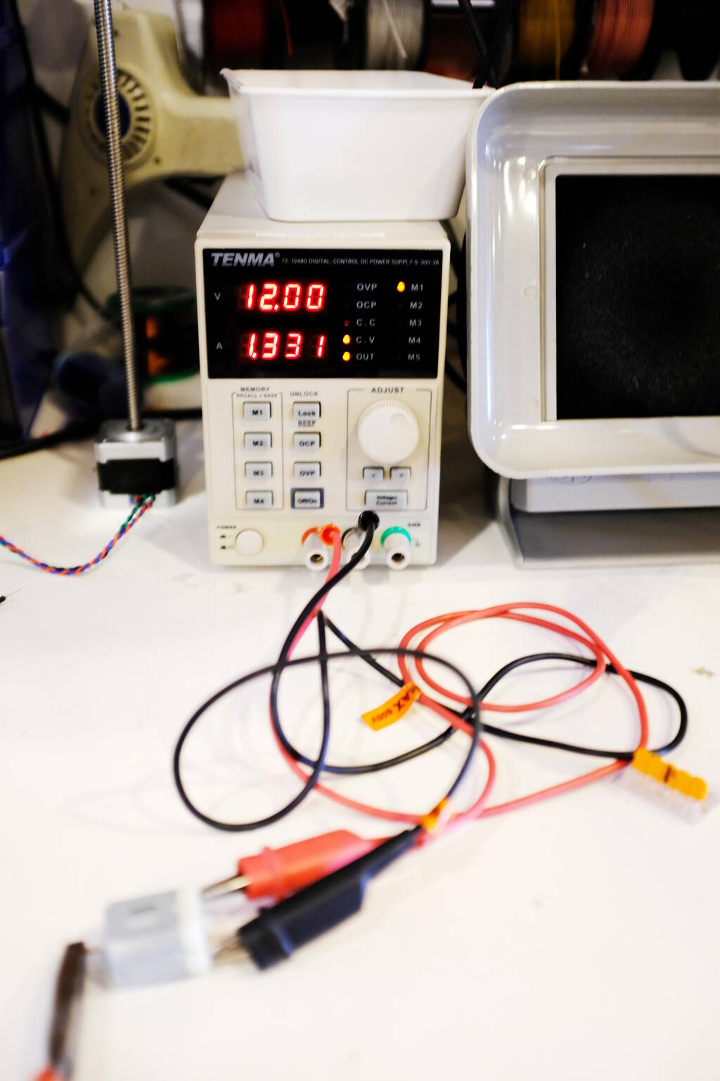
We did this while clamping it down:
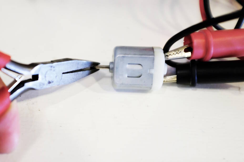
This means that the power of the motor is: P = V * I = 12 * 1.3 = 17 W. This gives us a power budget of 17 W / 50 W / kg * 1000 = 340 g. The motor itself weighs 30 g.
Determining a Power Source
Since we are critical on weight, we need to find a good power source. Let's do some measurements and calculations.
9V Battery
The first idea is to attach it to a 9 V battery. Unfortunately, now reality kicks in and we have to find out how much current it can deliver for this motor. We used a multi meter to measure the current while under load and found:
The current was 600 mA on maximum load. This means that we have power P = V * I = 9 * 0.6 = 5.4 W. This gives us a weight budget of 5.4 W / 50 W / kg * 1000 = 108 g. Since the battery itself is 47 g, the motor is 30 g, we have 31 g left for the frame and wings. We concluded this is not possible.
LiPo Batteries
After some research, it appeared that LiPo batteries are much more promising. We found 3.7 V LiPo batteries with a capacity of 1000 mAh that can deliver a current of 1.5 theoretically. In practice, it says it is only 1 A. A current of 1.5 would be perfect, because then with 3 batteries, we can get a voltage of 11.1 V with a current of 1.5 A giving us 16.7 W, close to the 17 W that we want. Additionally, the weight is only 18 g, so the total weight of batteries and the motor = 3 * 18 + 30 = 84 g in a weight budget of 340 g.
The capacity of 1000 mAh is of less relevance to us, because if we can make it fly only briefly it would already be good enough for us. With a capacity of 1000 mAh and a current of 1500 mA, we can fly for 40 minutes, so perfect for our goal.
Ornithopter Mechanical Design
Michelle did an awesome job Michelle documenting her, Ella, and Maria's progress last Friday and I was very impressed with what they achieved. Now it is Monday morning and I can see the design myself and there are various problems in my opinion:
- There is too much play on the axes and gears. This will make the gears slip.
- If you tighten the axis of the large gears, there is too much friction and we will lose power.
- The flapping angle is too little.
- The axes protrude too much causing there to be too much force on the front plate. This will give play and will make the gears slip as well.
- Currently, I don't see how we can make proper wings from the beams with holes.
Trying to find a rule of thumb about the flapping angle, it becomes clear that "all is connected". If we attach the beam that drives the wings further from the center of the large gear, the angle of the flapping will vary as well.
So, successfully flying will depend on the rotational speed of the motor, the gearing that transfers it to the motion of the beam, which controls both the flapping angle and the flapping speed...
To make this fly, we need a design that is highly parametric to figure out the right set of parameters. From the top of our head right now (I'm here with Maria):
- size of the wings,
- size of the gears,
- size of the crank
Collaboration
I'm trying to recreate a new frame, but I don't use Fusion and Michelle only provided STEP files. Trying to recreate a press-fit kit that works as well as Michelle's is going to take me hours to recreate it in FreeCAD, finding out all the right parameters. The STEP file does not have the parameters and the design differs from what came out in the end. So, Maria is going to ask for the Fusion files to redesign it in Fusion.
Play and Forces
In the mean time, I will work on getting the mechanical part better. The transfer from gear to gear is not working well, the transfer to the crank is bad, andthe transfer to the wing beams is also suboptimal:
Using bearings would make the design quite heavy and we know that we have a limited weight budget. My solution is to use 3D-printed pins of which I can change the parameters such that there is little play and the operation is quite smooth. As a proof of concept I made a small pin to attach the wings to the crank:
I simply copied the design of Michelle fixating all the pins in the same way that Michelle did:
However, what I didn't realize is that this will never work because now that there is a lack of play, the large gear can't turn because the beams of the wings can't move up and down. I realized that the play that Michelle has at the pivot points is actually necessary to make here design work. At this point, we opted to try my route and Michelle's route to find out what would be best. Michelle would try to tighten all the connections with gears except for the wing pivot points because her design needs that.
I instead would continue my design and add slots for the wings to move:
However, it was Tuesday 4 April by now, almost one week had past and we had decided beforehand to have a very promising flapping ornithopter working or move to other topics, such as bopping the head, dispensing eggs, etc. I felt that my design would be tricky because I needed bigger holes and pins, different pins and slots to constrain the wing movement vertically, so much experimentation to get smooth operation and good transfer. I felt that Michelle was closer to a working solution, but also she recognized how difficult it would be to make it work properly.
We had a serious discussion on what to do. Henk thought we had flown too close to the sun with our ideas of flapping wings. Ella and Maria had kind of worked on a walking mechanism, but this is very complicated as well.
I argued that no matter what we would do, we basically start from scratch except for flapping wings without a function. The reason is that the walking mechanism is new, the egg-laying would be a new mechanism, the bopping would be a new mechanism, etc. I suggested perhaps to focus on my original idea, namely an egg-shooting machine.
Reflections
My takeaways from this process are the following: The idea was ambitious and we fully realized this. We had a good plan with a fixed date to focus on different aspects.
We didn't succeed in making an ornithopter. Especially the weight budget restricted us quite in the design making it quite a challenging endeavor. I also felt quite restricted because the frame that was made by Michelle in Fusion worked well in terms of fitting the motor. Fusion is really not an option for me and I didn't want to redesign the thing in FreeCAD duplicating work. In hindsight, I think I should have redesigned it afterall making the holes bigger for stronger pins, and making an 3D assembly to understand the operation of the mechanisms.
Another thing that I realize is that it is difficult to judge where to spend time: is it worth it to spend hours for a 3D design without having something physical? Or is it better to first experiment in the physical world and then try to design it later in a 3D program or to not even design it. For me the former approach would work much better, but I noticed that Michelle and Samson preferred the latter approach.
Easter Egg Shooter
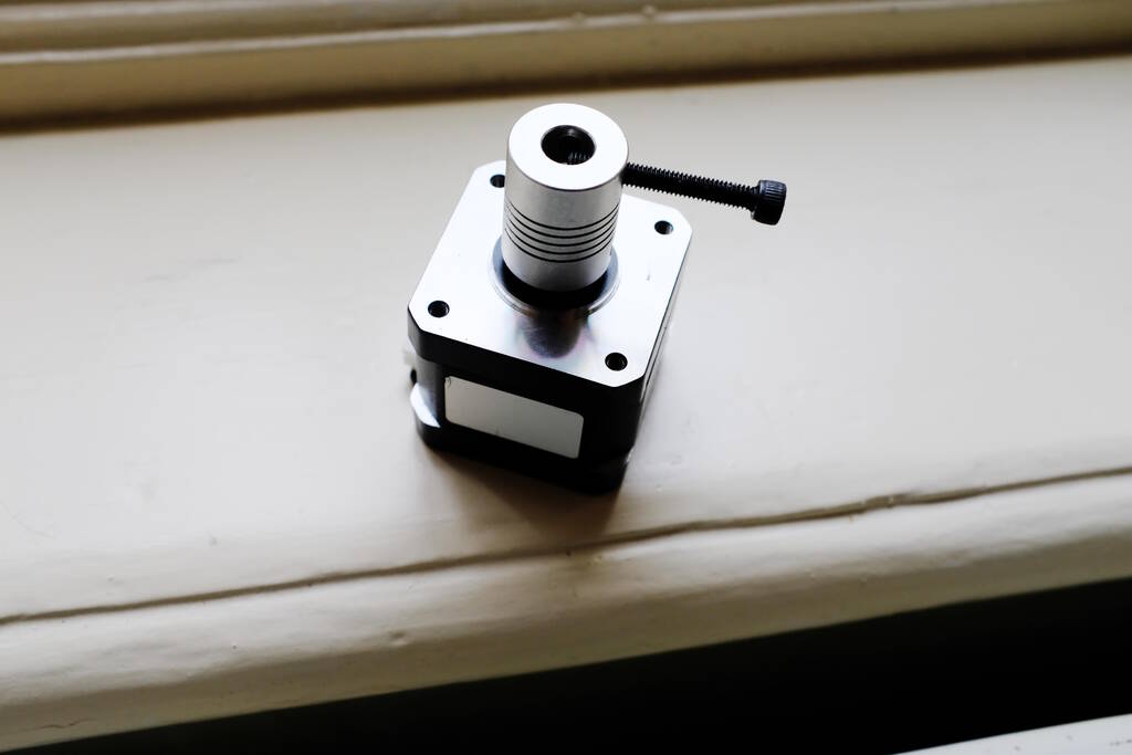
After we had decided to switch to a chocolate easter egg shooter, Samson made great progress in a launching mechanism and Michelle created a prototype of a mechanism that dispensed eggs. I was tasked with creating the turntable but unfortunately, I didn't have a clear thing in mind that would work well. I decided to first get the stepper motors to work.
Controlling the Stepper Motors
Since I had an idea to control the stepper motors from a distance with Bluetooth using the ESP32-C3, I preferred a solution that did not make use of libraries. Since Michelle and Samson were working on Arduino's I first focused on making it work with an Arduino Uno. I used one of Samson's A4988 stepper drivers.
From this tutorial I learned that you can find out the pair of wires that make a phase for the stepper motor by measuring continuity between two pins with a multimeter. If you find two of the four wires that short circuit, then these two wires make a phase and should be connected to either pin 1A and 1B or pin 2A and 2B. Which one is not important.
/*
 *   Basic example code for controlling a stepper without library
 *
 *   by Dejan, https://howtomechatronics.com
 */

// defines pins
#define stepPin 10
#define dirPin 11

void setup() {
  // Sets the two pins as Outputs
  pinMode(stepPin,OUTPUT);
  pinMode(dirPin,OUTPUT);
}
void loop() {
  digitalWrite(dirPin,HIGH); // Enables the motor to move in a particular direction
  // Makes 200 pulses for making one full cycle rotation
  for(int x = 0; x < 800; x++) {
    digitalWrite(stepPin,HIGH);
    delayMicroseconds(700);    // by changing this time delay between the steps we can change the rotation speed
    digitalWrite(stepPin,LOW);
    delayMicroseconds(700);
  }
  delay(1000); // One second delay

  digitalWrite(dirPin,LOW); //Changes the rotations direction
  // Makes 400 pulses for making two full cycle rotation
  for(int x = 0; x < 1600; x++) {
    digitalWrite(stepPin,HIGH);
    delayMicroseconds(500);
    digitalWrite(stepPin,LOW);
    delayMicroseconds(500);
  }
  delay(1000);
}
The Turntable Platform
I took inspiration from Quentin Bolsee's final project . His Photogrammetry 3D Scanner uses a circular bottom plate with a motor, a circular bottom plate that is the platform for the objects to scan. The platform rests on three wheels made out of bearings. I replicated the three rests and used wheels made from bearings as well:
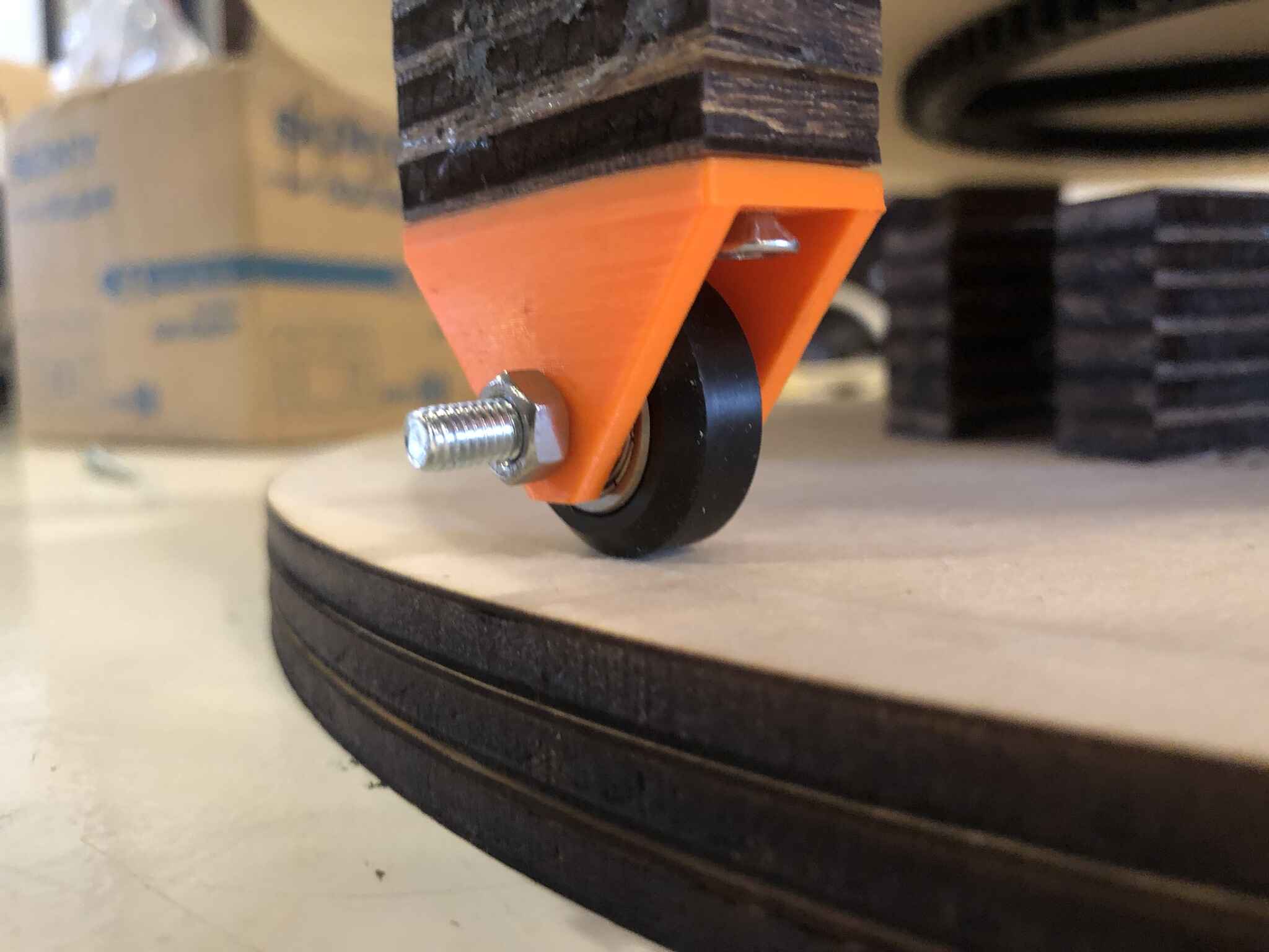
The supports that hold the wheels:

I wanted to mill the bottom plate and platform but Samson and Michelle suggested to laser cut a couple of plywood sheets and create the bottom plate from them. This also allows us to create channels for the cables.
The Mechanism for the Turntable
Quentin had a motor on the side with a small gear and the platform had a large 3D-printed gear. The gears were connected with a belt. I could have gone the same way, but to me this seemed to be an overly complex design for our use case. Quentin can drive 4 kg on his platform and our dispenser will be lighter.
Because of this, I thought about using no gears at all assuming that the motor had enough power. However, there is a chance of bringing the motor to the limit, so I tried to come up with something that would reduce the torque. From this point on I started to get confused and to mix concepts about torque and rotation. However, I learned much from this tangent and I will try to explain my train of thought and how I understand it now.
Misconception Torque
Suppose you have a door and you want to push it open. If you do this on the inside of the door, you need much force to do so, but if you push on the outside of the door, you need little force. This seemed logical to me because if you look at the unit for torque, Nm, pushing on the inside give is force applied over a small distance, whereas pushing on the outside is force applied over a large distance (because the radius is larger, the circumference is larger). So, if the torque is constant for both actions, the force measured in Newton can be smaller because it is compensated by a larger factor of distance.
So, based on this, I thought to be smart and use something like the following design:
My idea was that the head of the screw would push against the platform and the further the head of the screw would be out, the lighter it would be on the motor, in the same way that it is easier to push a door on the outside than on the inside. So, the length of the screw would determine how much force was required.
However, this was a misconception and it has to do with where the force originates from. In the case of pushing a door, the force comes from the outside of where the door rotates, so pushing on the inside requires more force than from the outside for the same amount of rotation because the force cannot be spread over a longer distance as is the case with pushing on the outside.
For the case with a motor at the center, the force to rotate comes from the motor itself, so it is kind of "part of" the rotational system and whether the motor pushes on the inside or an outside diameter does not change how much the platform turns. Discussing this with Erwin, he explained to me that for a motor, the diameter of the windings around the core of a motor effectively determine how much torque a motor has.
Using Beehive Fishing Line
As an alternative Henk suggested to copy the approach from the Beehive using fishing line, making something with a large "gear". I did not have much faith in this because it was perhaps even more complex than Quentin's design, but on the other hand, I really like the Beehive concept, so it was good to have a better understanding.
We tried many different ways to attach the center pole to the Beehive setup, here a picture of one of the setups:
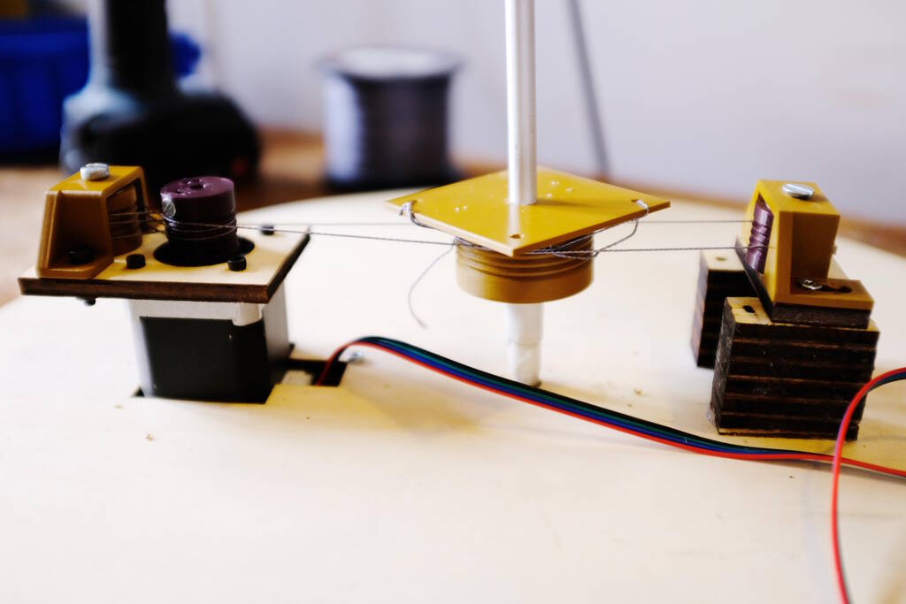
We tried winding the wire around the center platform, and we tried tying the wires to the platform but all these options failed because of one fundamental problem: The play at the center pole was to much to get a proper tension between in the wire. Because of this, the wire would always slip at some place making the whole solution ineffective. The play the system has:
The lack of tension:
What we learned from this is that the Beehive concept with fishing line can work well, but you need to have a mechanism with little play to be able to tension the fishing line for it to grip. Unfortunately, this didn't work, but we learned much from it.
Using a Large Gear
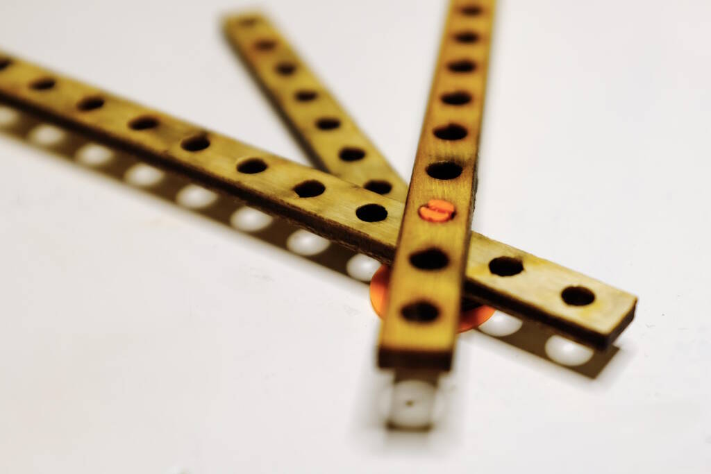
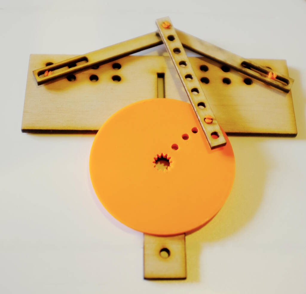
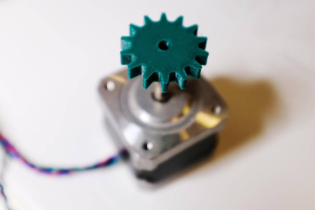
I don't know why I didn't come up with this idea sooner, but something Samson said triggered me and make me think of a mechanism of which I was sure to reduce the torque and was easy to execute. We had a motor with a small gear on it:
What if I simply drive a larger gear attached to the platform. I would only require a large gear that I could laser cut, attach it to the platform and place the motor such that it would drive this large gear.
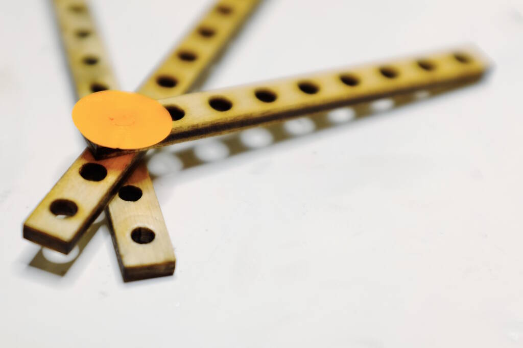
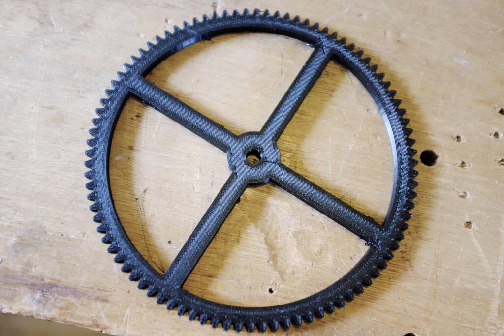
I measured the gear:

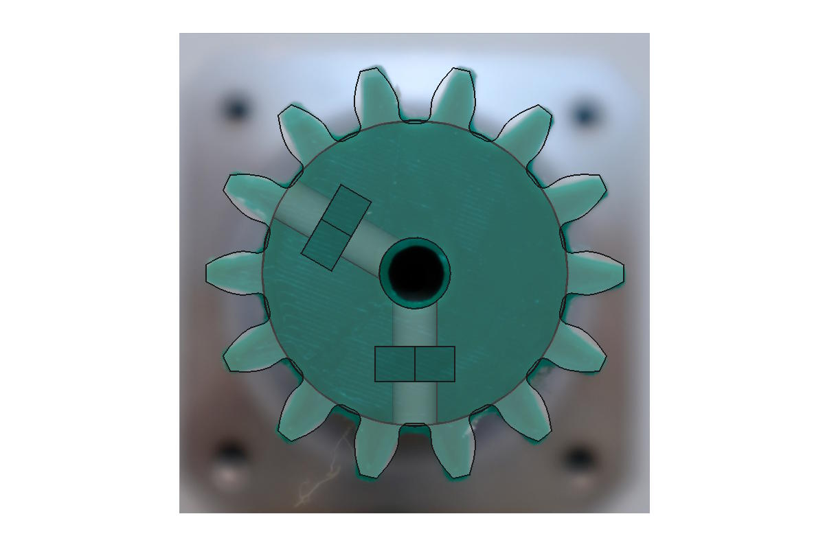
Took a photo to use in FreeCAD to design the gear:
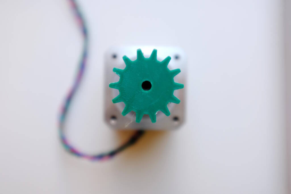
Incorporate this image in FreeCAD to design a similar gear:
We could go with the original motor with the green gear on top, but to be sure I also printed an equivalent gear that we could fit on a different motor. This was important to be extra flexible in terms of height of the platform:

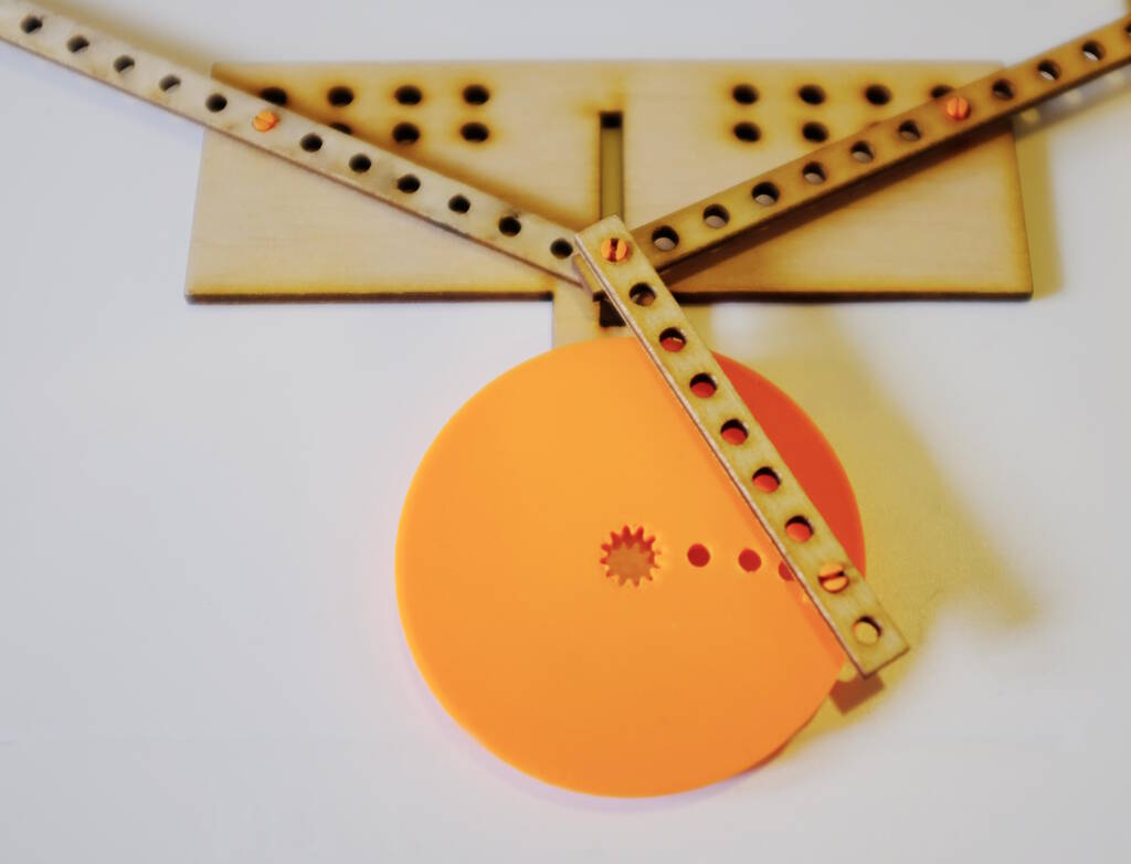
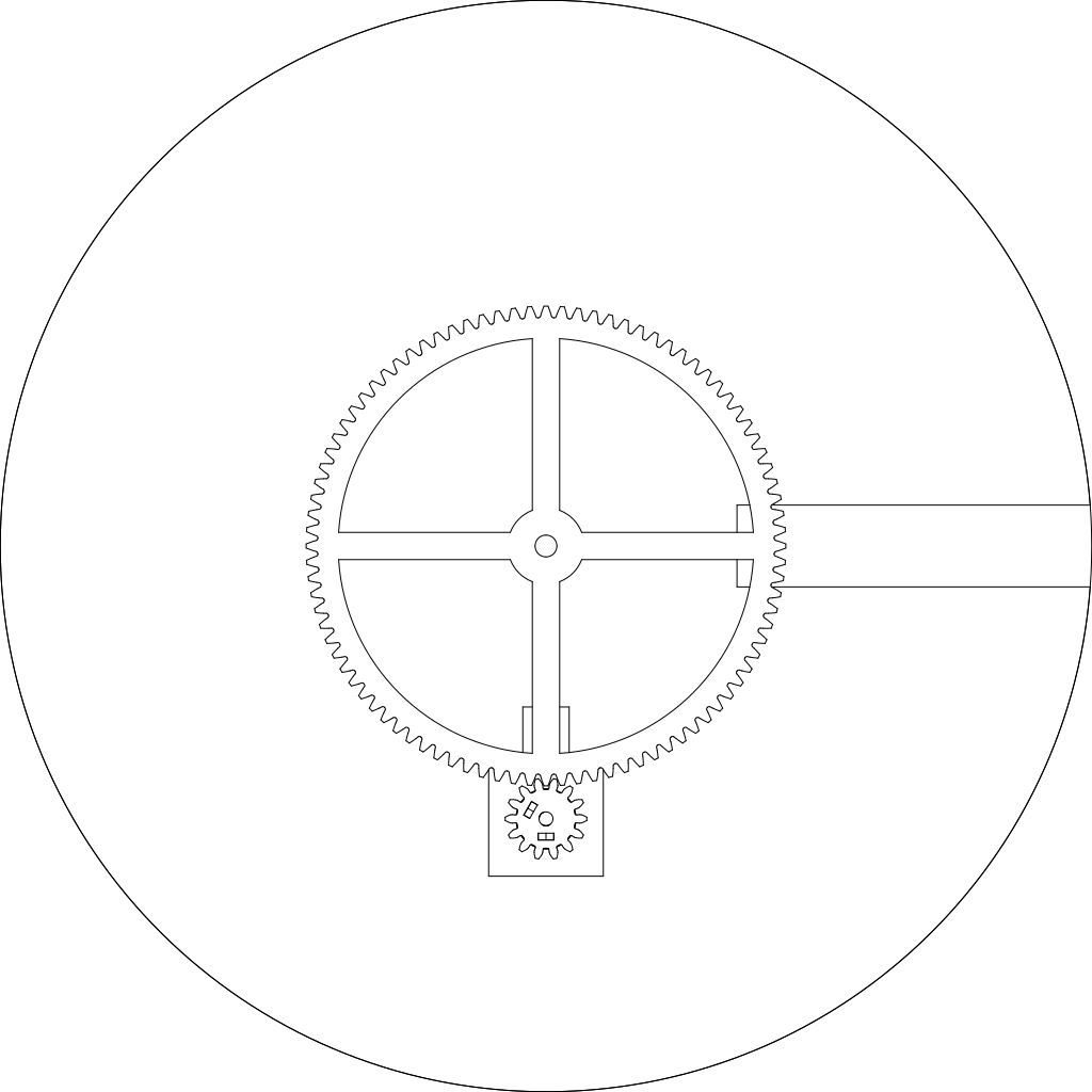
Based on this I designed the large gear for the platform. Everything layed out, such that I could fit it immediately after Easter:
The 3D printed version:
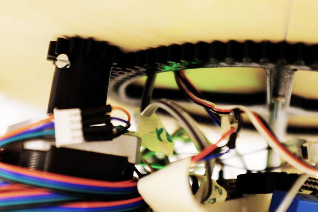
The mechanism working:
A picture of the underside of the platform with the gears:
Bluetooth Connection
Although we didn't use it in the end, I spent some time to try to control the Easter Egg Shooter separately using ESP32s. I used this server example and this corresponding client example and adjusted it to our needs. I can simply communicate "rotate the platform left", "rotate the platform right", and "launch an easter egg". I also added an LED to the code to give a visual cue that we have connection.
This video shows that it works, the distance is about 10 meters, so plenty of range. Note that the right side is the screen of a different computer with some distance between the computers:
Refactoring the Code
Samson and I had difficulty understanding the code, so I couldn't resist the urge to refactor the code such that I could understand it as well. It is a simple process but it makes the code so much easier to read. Below the original code:
#include <Servo.h>

int servoPin = 6;
int servoPos = 0;
int servoPin2 = 10;
int pos = 0;
Servo myServo1;
Servo myServo2;

int dcPin = 5;

int inputPin = 7;  // input pin for pushbutton

#define dirPin 8
#define stepPin 9

int leftPin = 16;
int rightPin = 15;
int upPin = 14;
int downPin = 17;

int leftValue = 0;
int rightValue = 0;
int upValue = 0;
int downValue = 0;


void setup() {
  // put your setup code here, to run once:
  Serial.begin(9600);
  myServo1.attach(servoPin);
  myServo2.attach(servoPin2);
  pinMode(inputPin, INPUT);  //declare pushbutton as input
  pinMode(stepPin, OUTPUT);
  pinMode(dirPin, OUTPUT);
  pinMode(leftPin, INPUT_PULLUP);
  pinMode(rightPin, INPUT_PULLUP);
  pinMode(upPin, INPUT_PULLUP);
  pinMode(downPin, INPUT_PULLUP);
  pinMode(dcPin, OUTPUT);

}
void loop() {
  // put your main code here, to run repeatedly:
  int val = digitalRead(inputPin);  //read input value
  if (val == HIGH)   { //check for input is HIGH
    digitalWrite(dcPin, HIGH);   // turn the RELAY on
    delay(3000);                     // wait for a second

    for (servoPos = 115; servoPos >= 30; servoPos--) {
      myServo1.write(servoPos);
      delay(3);
    }
    for (servoPos = 30; servoPos <= 115; servoPos++) {
      myServo1.write(servoPos);
      delay(3);
    }
    delay(20);

    for (pos = 0; pos <= 120; pos += 1) { // goes from 0 degrees to 180 degrees
      // in steps of 1 degree
      myServo2.write(pos);              // tell servo to go to position in variable 'pos'
      delay(50);                       // waits 15ms for the servo to reach the position
    }

    for (pos = 120; pos >= 0; pos -= 1) { // goes from 180 degrees to 0 degrees
      myServo2.write(pos);              // tell servo to go to position in variable 'pos'
      delay(15);                       // waits 15ms for the servo to reach the position
    }
  }
  digitalWrite(dcPin, LOW);    // turn the RELAY off

  leftValue = digitalRead(leftPin);
  rightValue = digitalRead(rightPin);
  upValue = digitalRead(upPin);
  downValue = digitalRead(downPin);

  Serial.println(leftValue);
  Serial.println(rightValue);
  Serial.println(upValue);
  Serial.println(downValue);


  if (leftValue ==  LOW) {
    digitalWrite(dirPin, HIGH); // Enables the motor to move in a particular direction

    digitalWrite(stepPin, HIGH);
    delayMicroseconds(700);    // by changing this time delay between the steps we can change the rotation speed
    digitalWrite(stepPin, LOW);
    delayMicroseconds(700);
  }
  if (rightValue ==  LOW) {
    digitalWrite(dirPin, LOW); //Changes the rotations direction
    // Makes 400 pulses for making two full cycle rotation
    digitalWrite(stepPin, HIGH);
    delayMicroseconds(500);
    digitalWrite(stepPin, LOW);
    delayMicroseconds(500);
  }
}
Let me try to explain what makes it so difficult to understand: There are two
servo motors but they are called
myServo1
and
myServo2
with
servoPin
and
servoPin2
. First, this naming is inconsistent,
but more severe is that the naming does not reflect the semantics. The two
servos have different functionality and in this code it is not clear which
one is the servo pushing an egg and which one is dispensing eggs.
I can imagine a situation in which the two servos have the same functionality
and in that situation the naming scheme could be acceptable, albeit that I
would probably give them a name based on location then. Then in
loop()
there are suddenly magic numbers such as
115
,
30
,
3
, etc. These numbers most likely have a meaning and from this code
it is unclear what the meaning is. So, to figure out what this code does, we
have to change one of the numbers and try to spot the effect that it has.
The third major problem is that the
loop
function is very long. It
has several if-statements with for-loops inside and there is essentially no
separation between the different kinds of functionality.
Finally, the code looks well documented, but many of the comments can be removed if the code had better structure and would be closer to the semantics of the functionality it implements.
The code below is the same code but then refactored:
#include <Servo.h>

/* We have two DC motors attached to wheels that will launch the easter eggs.
 * We will call them the launcher DCs.  There is a relay, the launcher_relay
 * that turns the motors on.
 *
 * We have two Servo motors, one dispensing an easter egg and one to push the
 * egg into the wheels.  Let's call the first one the dispense servo and the
 * other one the push servo.
 *
 * Finally, there is a turntable that rotates left or right.
 */


#define LAUNCHER_RELAY 5
#define LAUNCHER_DC_DELAY 3000

#define LAUNCH_PIN 7

#define DISPENSE_SERVO_PIN 6
#define DISPENSE_DELAY 3 // milliseconds
#define EGG_ROLL_DELAY 20 // milliseconds
#define DISPENSE_START_POS 115
#define DISPENSE_END_POS 30

#define PUSH_SERVO_PIN 10
#define PUSH_DELAY 50 // milliseconds
#define MOVE_BACK_DELAY 15 // milliseconds
#define PUSH_START_POS 0
#define PUSH_END_POS 120

#define UP_PIN 14
#define RIGHT_PIN 15
#define LEFT_PIN 16
#define DOWN_PIN 17

#define DIRECTION_PIN 8
#define ROTATE_PIN 9
#define STEPPER_DELAY 700 // microseconds


Servo dispenseServo;
Servo pushServo;

void setup() {
  // put your setup code here, to run once:
  Serial.begin(9600);

  // set up the servos
  dispenseServo.attach(DISPENSE_SERVO_PIN);
  pushServo.attach(PUSH_SERVO_PIN);

  pinMode(LAUNCH_PIN, INPUT);  //declare pushbutton as input

  pinMode(LEFT_PIN, INPUT_PULLUP);
  pinMode(RIGHT_PIN, INPUT_PULLUP);
  pinMode(UP_PIN, INPUT_PULLUP);
  pinMode(DOWN_PIN, INPUT_PULLUP);

  pinMode(LAUNCHER_RELAY, OUTPUT);

  pinMode(DIRECTION_PIN, OUTPUT);
  pinMode(ROTATE_PIN, OUTPUT);


}

void dispenseEgg() {
  for (int pos = DISPENSE_START_POS; pos >= DISPENSE_END_POS; pos--) {
    dispenseServo.write(pos);
    delay(DISPENSE_DELAY);
  }
  for (int pos = DISPENSE_END_POS; pos <= DISPENSE_START_POS; pos++) {
    dispenseServo.write(pos);
    delay(DISPENSE_DELAY);
  }
  delay(EGG_ROLL_DELAY);
}

void pushEgg() {
  for (int pos = PUSH_START_POS; pos <= PUSH_END_POS; pos += 1) {
    // goes from PUSH_START_POS degrees to PUSH_END_POS degrees
    // in steps of 1 degree
    pushServo.write(pos);
    delay(PUSH_DELAY);
  }

  for (int pos = PUSH_END_POS; pos >= PUSH_START_POS; pos -= 1) {
    pushServo.write(pos);
    delay(MOVE_BACK_DELAY);
  }
}

void loop() {
  if (digitalRead(LAUNCH_PIN) == HIGH) { // we are launching an egg
    digitalWrite(LAUNCHER_RELAY, HIGH);
    delay(LAUNCHER_DC_DELAY); // wait a bit to the DCs are up to speed

    dispenseEgg();

    pushEgg();
  }
  digitalWrite(LAUNCHER_RELAY, LOW);

  int leftVal = digitalRead(LEFT_PIN);
  int rightVal = digitalRead(RIGHT_PIN);
  int upVal = digitalRead(UP_PIN);
  int downVal = digitalRead(DOWN_PIN);

  Serial.println(leftVal);
  Serial.println(rightVal);
  Serial.println(upVal);
  Serial.println(downVal);

  if (leftVal ==  LOW) {
    digitalWrite(DIRECTION_PIN, HIGH); // Enables the motor to move in a particular direction

    digitalWrite(ROTATE_PIN, HIGH);
    delayMicroseconds(STEPPER_DELAY);
    digitalWrite(ROTATE_PIN, LOW);
    delayMicroseconds(STEPPER_DELAY);
  }

  if (rightVal == LOW) {
    digitalWrite(DIRECTION_PIN, LOW);
    digitalWrite(ROTATE_PIN, HIGH);
    delayMicroseconds(STEPPER_DELAY);
    digitalWrite(ROTATE_PIN, LOW);
    delayMicroseconds(STEPPER_DELAY);
  }
}
An important factor in writing proper code is to name things well. The code above starts with a comment that explains the background of the naming scheme. The code then has several constants with names that try to reflect what the value of the constants mean. Some numbers have units in comments.
The servos are called
dispenseServo
and
pushServo
reflecting
the task of the servo, making it clear immediately which servo we are dealing
with. For example, it allows us to spot a mistake if we initialize the
dispenseServo
with the
PUSH_SERVO_PIN
for example, something
that is very difficult to do if the names are essentially numbers.
The
loop()
function is refactored into a
dispenseEgg()
and
pushEgg()
function that shows the reader what is done to dispense an
egg or to push an egg respectively.
The benefit of the code above is that we can easily tweak the timing of enabling the motors by just modifying some of the constants at the top of the file. The constants have better names, making it easy to understand which constant needs to be modified to reflect a change we desire.
Making the Video
To make the video, I created a shot list, planning the takes and making sure that I had the right people at the right moment to take some videos. This allowed me to record some videos for which I didn't need the final product to work. It also allowed me to gather the videos that we had already recorded.
The editing was done Kdenlive and nothing fancy was used. It was just shots of video with titles inbetween. I simply used the original sound from the recorded videos and I put a track underneath that Samson found on some website and was in the public domain.
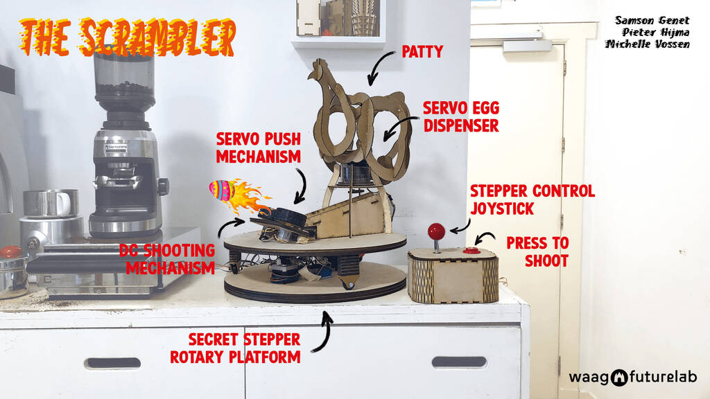
The final video was done right before our regional review, so it was tight, but I made it:

The resulting video:
This is the poster that Samson and Michelle created:
Tasks
Fab Academy
- Design a machine that includes mechanism + actuation + automation + application
- Build the mechanical parts and operate it manually.
- Actuate and automate your machine.
- Recognise opportunities for improvements in the design.
- Include an aprox. 1 min video (1920x1080 HTML5 MP4).
- Include a slide (1920x1080 PNG).
Personal
- Add the Bluetooth functionality to the machine.