Mid semester Project:

The project
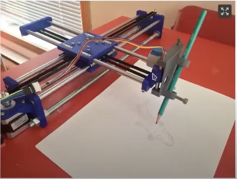
Together wil my team mate Constanza Cipriani, we have decided to build a plotter and for logistic reason, we had to split the work into tow pieces: Costanza will take care of the mechanical components and assembly of the same, and I will take care of all the electronics and SW prepararion. The final stage of integration will be done jointly.
HW components selection and HW architecture:
Overview of the main HW electronical components:
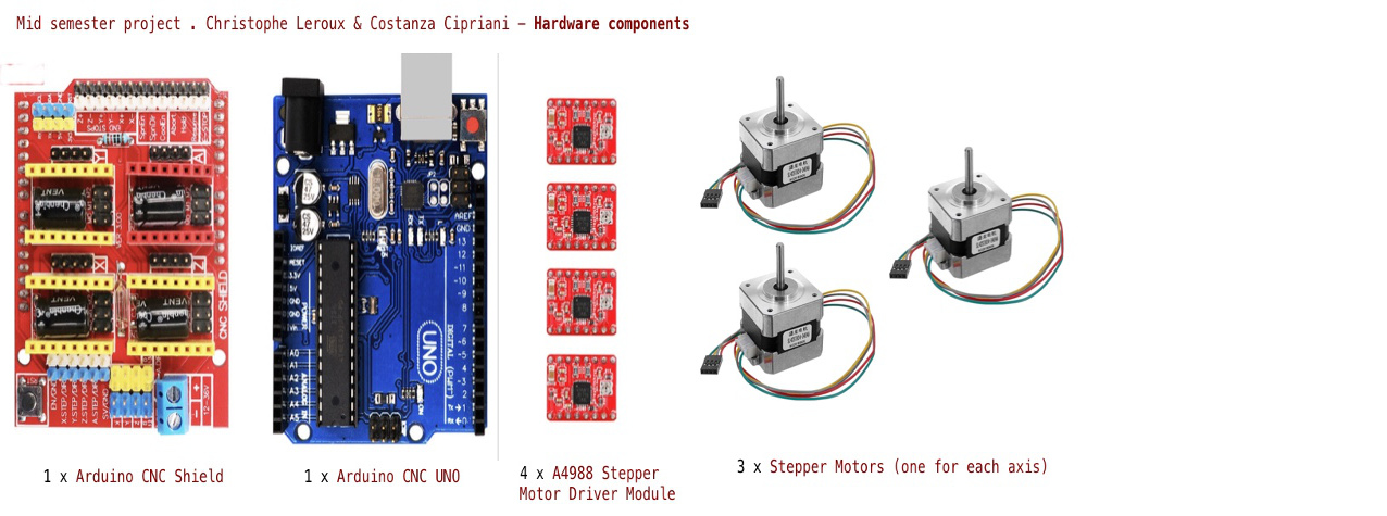
The Arduino CNC Shield is a central component in this electronic set-up: the CNC Shield PCB is an extremely powerfull and low cost solution to control a CNC Machine
This PCB is natively interfaceable with the Arduino Uno expanding the Arduino UNO to provide all the necessary features for a CNC Machine:
Using this CNC Shield will defintely ease our life in the project and make us spare time.
Simplified workflow overview:
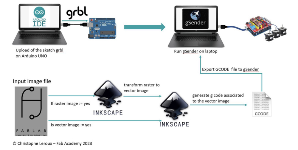
In the sections below, we will in details through the different steps and sub-steps summarized in the workflow.
Step 1, GRBL installation:
The Grbl is an open source SW for controlling the motion of machines that move, that make things, or that make things move, and will run on a straight Arduino. This open source from GRBL has massively used and adapted in hundreds of projects including laser cutters, automated hand writers and drawing machines.
Dowload of the right installation package on the GRBL GitHub repository (github.com/gnea/grbl/wiki)
Considering that I was using Arduino IDE 2.x I havd downloaded the following package:
https://github.com/gnea/grbl/wiki/Compiling-Grbl#if-you-are-using-arduino-ide-2x
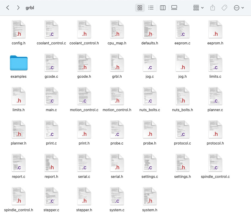
After downloading the grbl-master.zip, I have unzipped the grbl subfolder and copied it to the Arduino sketchbook folder. In case you don't know how to locate the Arduino sketchbook folder, open the Arduino IDE preferences (File > Preferences) and looking at the path shown in the "Sketchbook location".
In my case, i am using a mac and the Arduino sketchbook folder is the following:
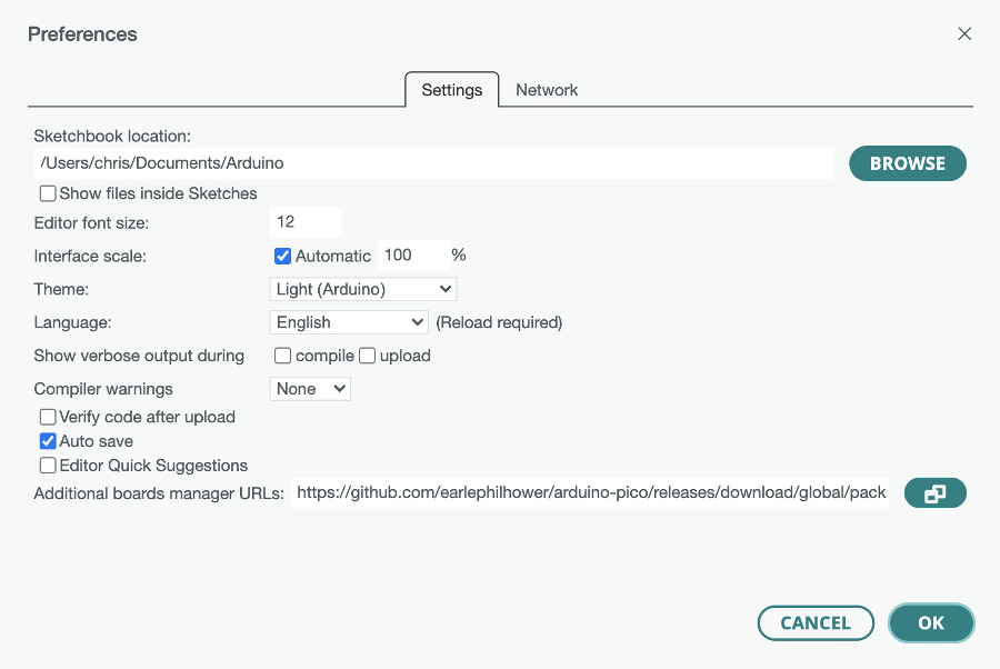
Preview of the Documents/Arduino/Libraries/grbl/ after copying the grbl subfolder files from the grbl.master.zip
After that I launched the Arduino IDE then go to menu File > Examples > grbl > grblUpload from the Arduino IDE menus. /
It's extremeòy important not to alter this exmaple file that would lead to a failure in the compilation operations later on
I have then connected my ARDUINO UNO to my MacBook via the USB port
Then I selected the correct Arduino version : in the menu Select Tools > Board > Arduino AVR Boards > Arduino Uno from the Arduino IDE menus
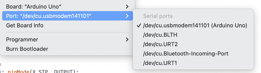
Then it came to the selection of the right port of communication. in the menu, Tools > Port
Then upload the sketch on the Arduino : menu, Select Sketch > Upload
Add photo or video of the test here
Step 2, quick check on the 3 Stepper motors and the 3 Pololu A4988 stepper drivers:
I have used the code taken from the internet (https://www.adrirobot.it/cnc-shield-v3-per-a4988-drv8825-controller/) to quickly test my HW configuration
Video of the test performed:
Step 3, generation of the g code associated to an image:
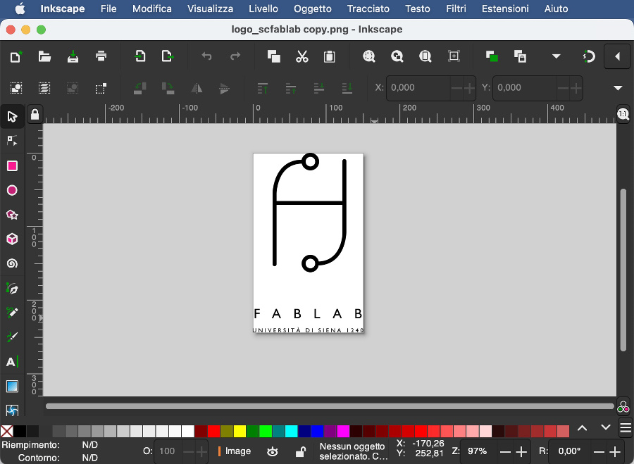
During this step, we will select a raster file image (logo if the Santa Chiara Lab) and use Inkscape SW to transform it into a vector image.Santa Chiara lab logo used for all the demo of the mid-semester assigment:
Open the image file (in this case the .png file of the Santa Chiara logo) in Inkscape.
Select of the image (only one click):
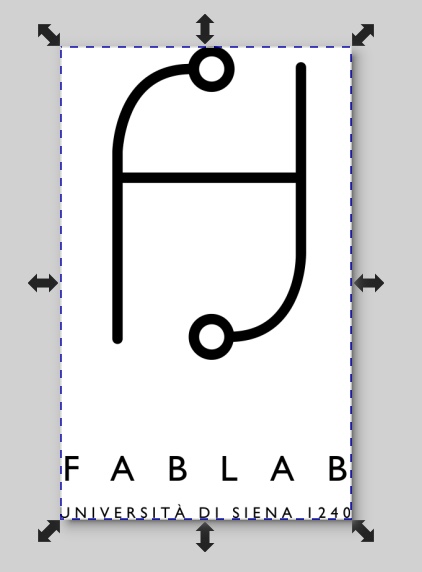
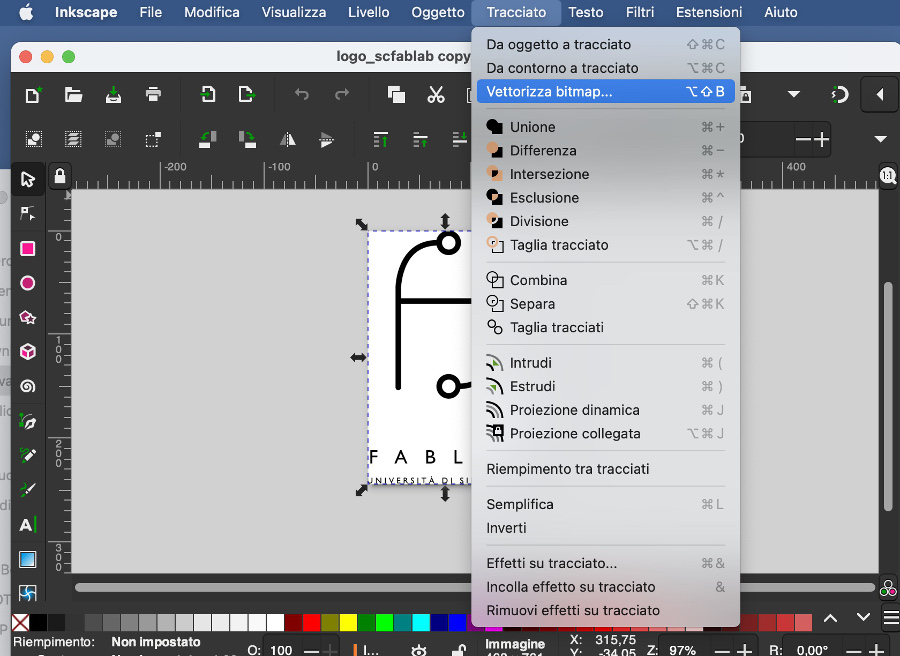
Since the image is not a vector, we have first to transform it from raster to vector.
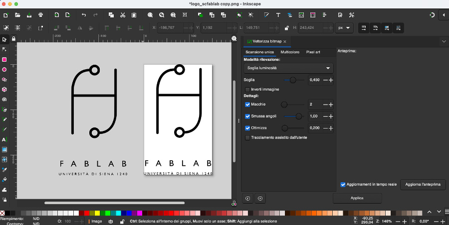
menu > Chemin > vectorize bitmap
At this stage be cautious since you have 2 images that are superposed: the raster one and the vector one just created
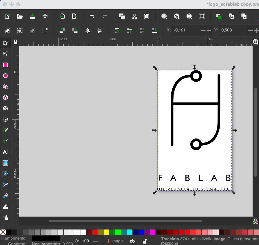
Click on the image to split it and move one of them so that you place them next to each other
At this stage, eliminate the raster version and keep only the vector image. If you have difficulties to distinguish the raster from the vector, just zoom in thill the point where you see that one of the two will start to pixelate on the outline.
Select the image (with only one click)
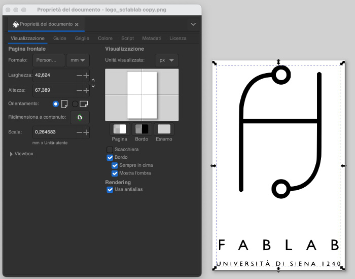
To create an empty border around the image, go to menu > File > Document properties:
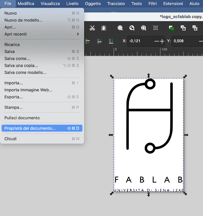
Click on the "+" button to slightly increase (around 10%) the width and the height of the image creating an empty border:
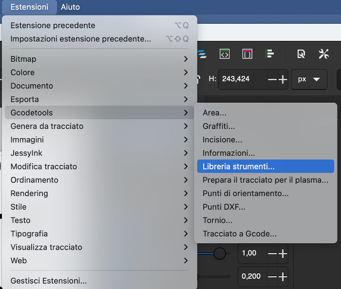
Go to Menu > Extensions > Tools library
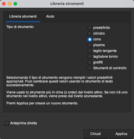
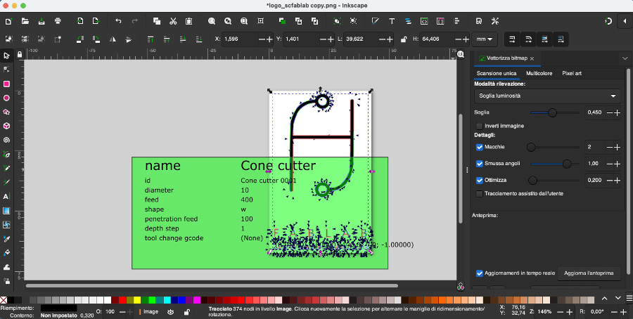
Since we will be using a pencil in our tracer machine, select "Cone" as the correct "Type of instrument"
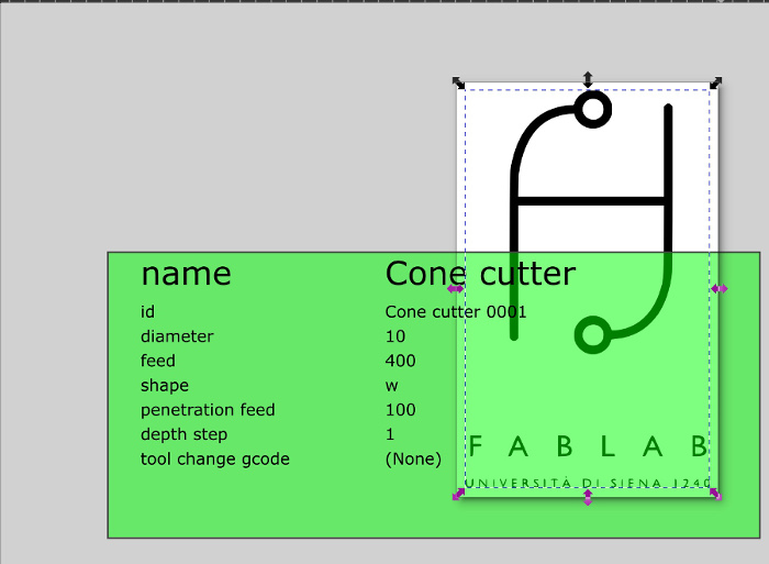
As per screen below, the previous choice of the cone gets reflected on the user interface:
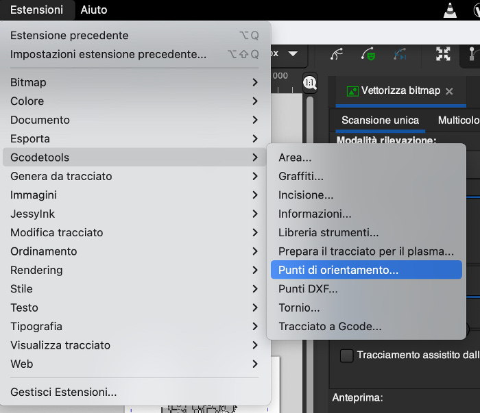
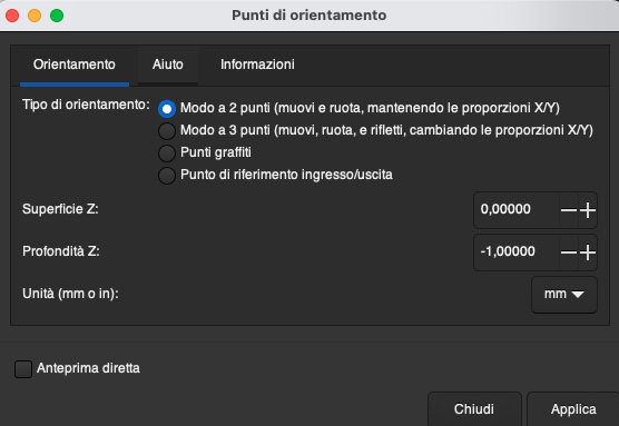
Go to Menu > Extensions > Gcodetools> Points of orientation
Select the option "2 points mode (move and rotate keeping the X/Y aspect ratio)
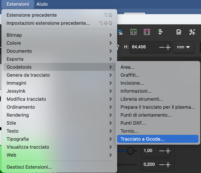
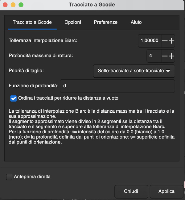
Go to Menu > Extensions > Gcodetools> G code track
On the main screeen "G Code track", keep the default parameters as per screen below and click on Apply
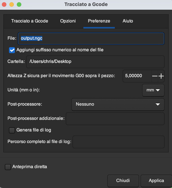
Then move to the sheet "Preferences" and do not forget to select the right folder where the G Code file will be created. Click on Apply.
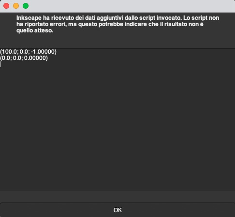
The script is executed and no error were encountered:
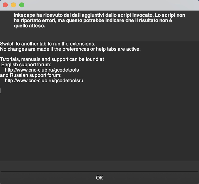
The script is executed and no error were encountered:
Overview of the Inkscape interface with the image and the path of the CNC.
Since all the process was smoothly executed, the G Code output file is available in the directory selected in the preferences:

Add a video of the test here
Step 4, UGS SW (or similar) installation:
The initial plan was to install UGS (https://winder.github.io/ugs_website/) but for unknown reason, I was not able to carry-on the deployment on my Macbook. The failure in deployment repeated for both versions version 2.0.13 and 2.0.14 (MacOSX versions with bundled Java).
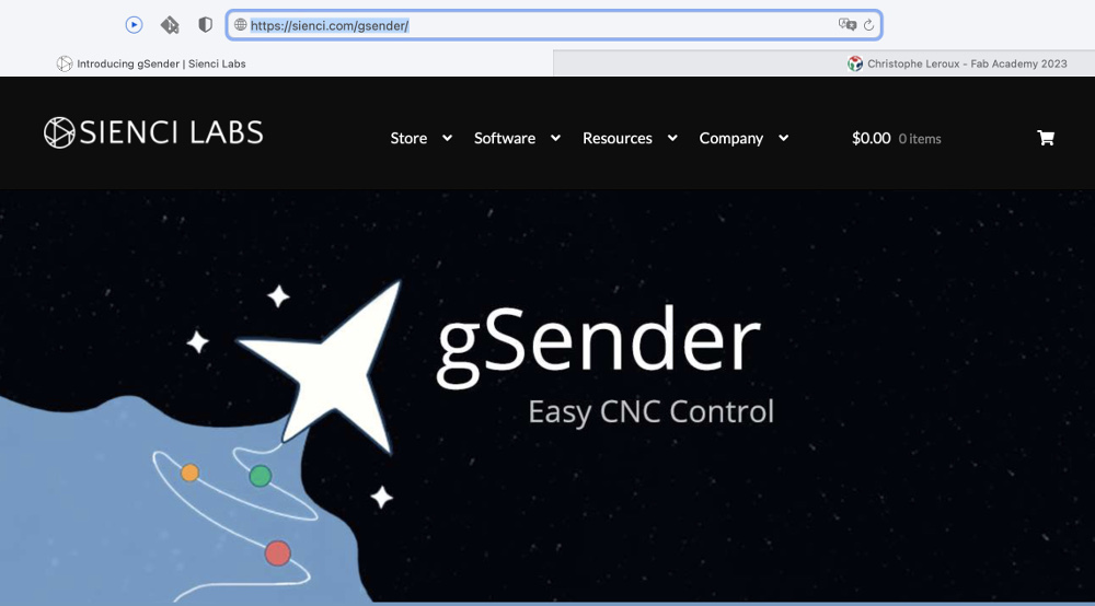
At this point, I had to find an alternative SW abd after some search, it sounded like gSender SW could be a valid alternative
I have downloaded gSender SW from the follwing Website: https://sienci.com/gsender/ and installed it without any issue on my Mac :)
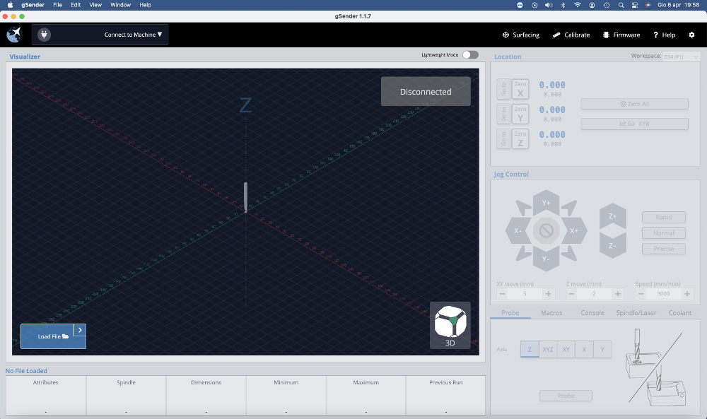
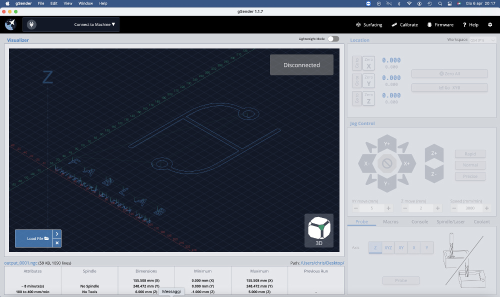
Overview of the gSender interface:
Load the input file using the "Load File" button:
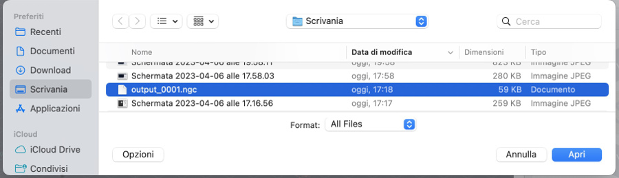
Select the right .ngc file to load:
Overview of the interface after file .ngc is opened. We recognize the logo of the Santa Chiara Lab.
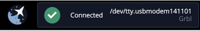
Right after selection of the file, selection of the device (Arduino Uno) and correct port where the device is connected to establish the connection:
At this stage, we can test the integration between HW and SW by cliking on the "start job" button.

Important note: the rest of the electronical and SW integration test are available at the following link that's a page summarizing the work done with my classmate Costanza.