My Final Project:

Genesis of the idea...
The final project's journey started in this way: idea was to create a square panel covered with a patterm of flowers (fake ones made of paper or Vinyl)
These flowers would open and close when the sun rises and humans in the room wish to shield the light in the room
In the beginning, I sketched on paper two types of flowers that looked nice and were complementary in terms of shapes
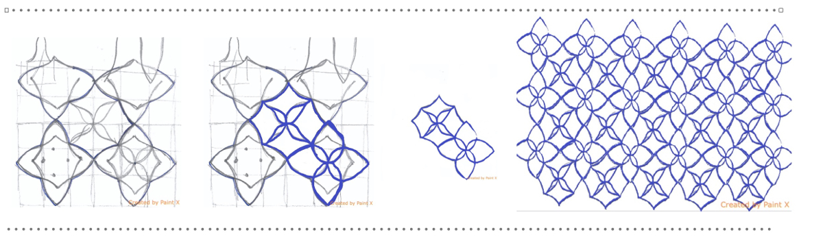
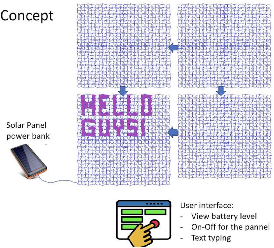
This panel has a primary use case that is to shield the light when it becomes too intense. Another interesting an unexpected use case is to create letters with this pattern of flowers to display text

Overview of the components and overall concept:
Evolution of the first concept...
Step by step this first idea got more mature and evolved in another direction: the creation of a form that evolves according to ambient sounds (whether noise related to human presence and/or music)
This form will integrate soft lights that will filter through its thin envelope made of paper (most probable material to be confirmed) or another thin and natural material
It is an object that could typically accompany art exhibitions, be integrated in spaces dedicated to rest and meditation, lobby of offices, houses.
During my first investigations targetted at identifying main building blocks, I always kept in mind that I wanted to exclude typical mechanical actuators and therefore an alternative need to be identified.
The reason for excluding classical actuators is to avoid heavy and noisy elements that would be difficult to hide in the object.
At some point, the discovery of flexinol as a potential very innovative actuator was a revelation and the current project is based on the usage of this material.
Flexinol material highlights
This material has a unique ability to flex or shorten is characteristic of certain alloys that dynamically change their internal structure at certain temperatures.
Flexinol (R) is made of nickel-titanium. Small diameter wires built with Flexinol contract like muscles when electrically stimulated.
This inspiring video on YouTube illustrates how Flexinol can be used to create complex structures with moving form.
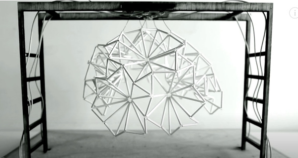 YouTube full video available here
The idea is to use the flexinol as innovative actuator / muscle attached to a highly flexible and tranformable skeletton structure: an Origami structure
The idea is toleverage an intrinsic quality of origami : their ability to shrink dimensions while ensuring simple deployment.
First partial test (one sheet of PostIt) and wire of Flexinol for actuator was run during the "Week09 - Output device".
As we can see on the screenshots below, when we press the button, the battery current flows through the flexinol causing its contraction and closure of the folded paper".
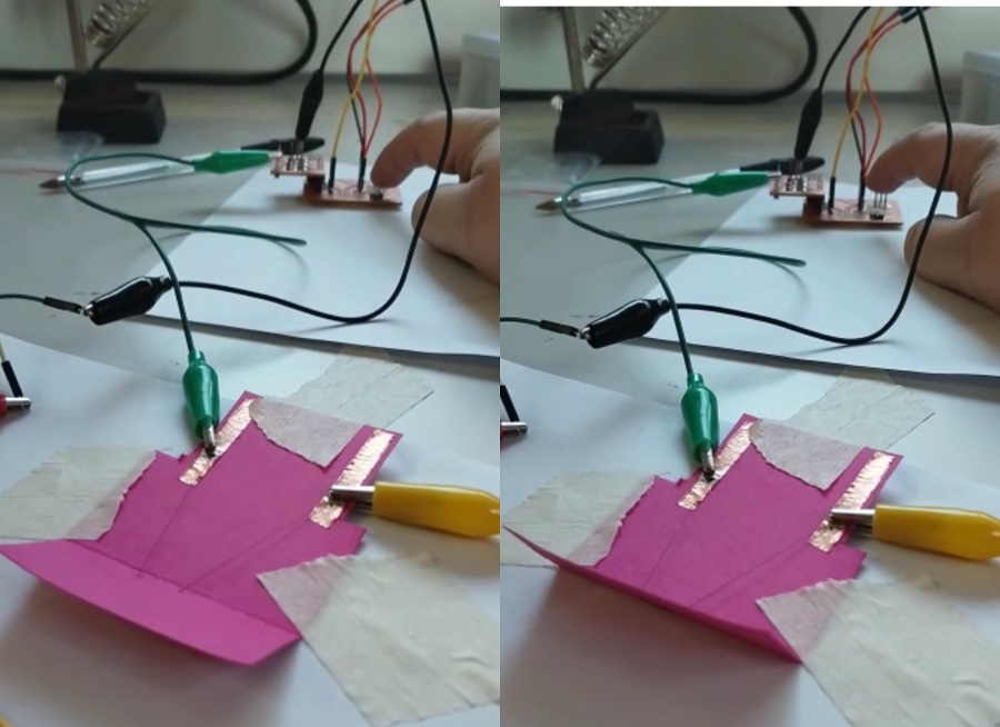
After this first successfull attempt, next step was to create a real Origami and test the second set of thicker Flexinol wire we received in the Fablab.
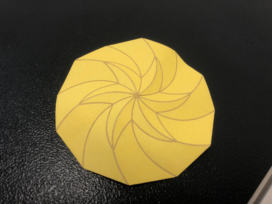
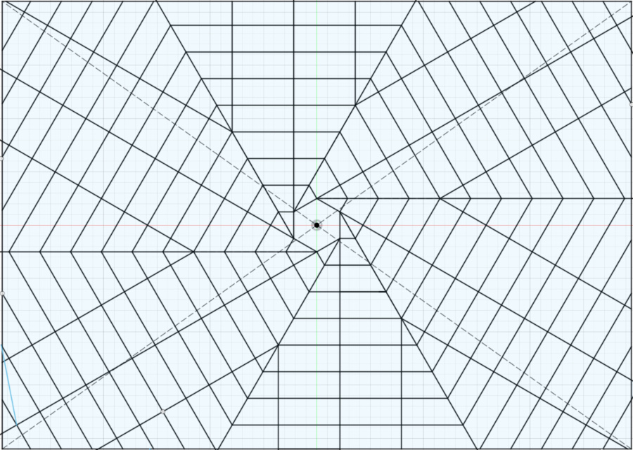
The origami structure that I selected is the rotating star:

Creation of the Origami following the steps detailed in the wildcard week
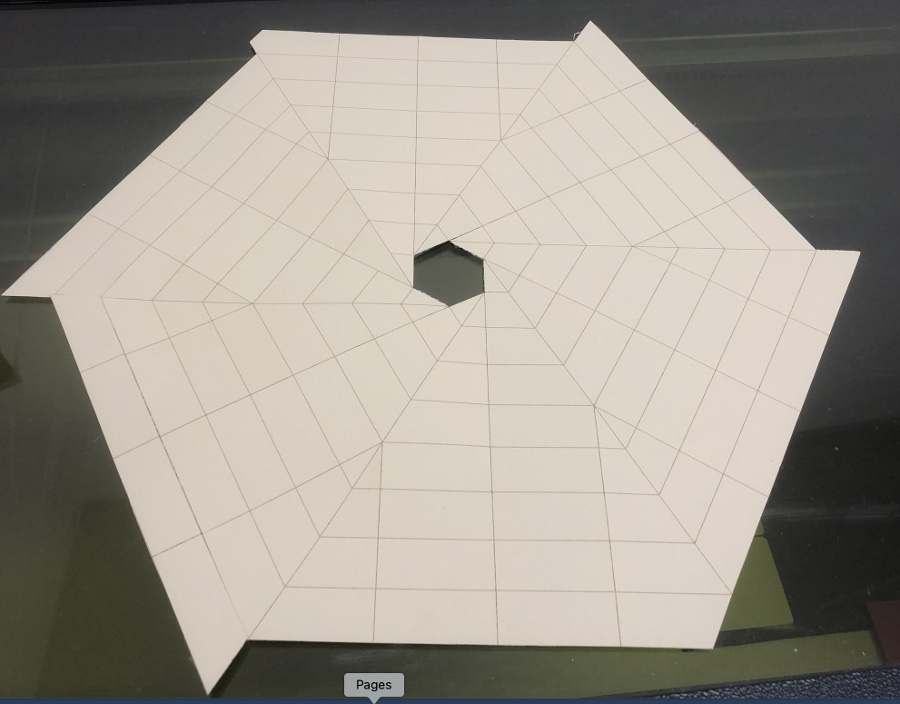
Overview of the output after cut and incision:
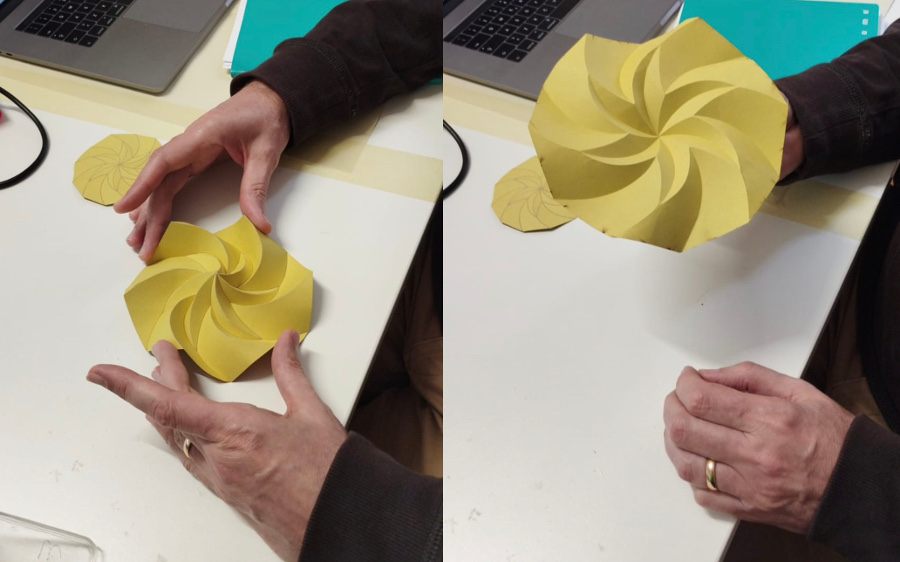
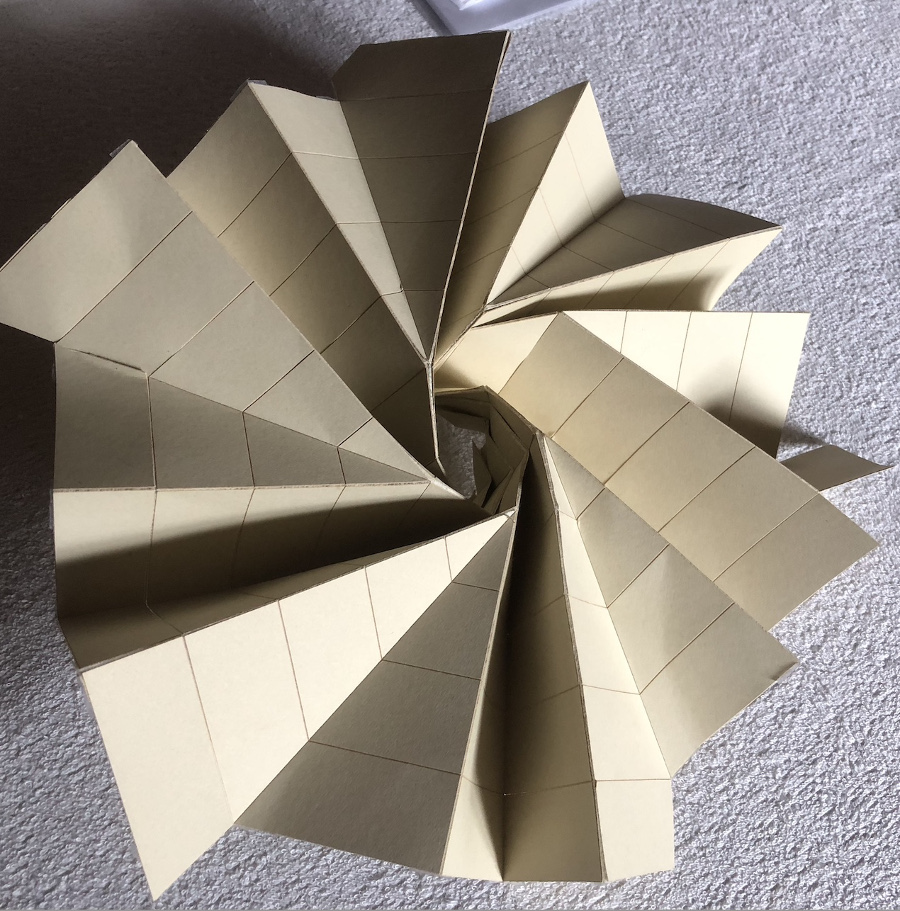
Overview of the output after folding of the Origami:
At this point I started working on adding the flexinol on the Origami.
To do that, I passed the flexinol thread through the hole of a copper rivet that I crushed with a hammer. At this point, it was easy to weld everything onto the Origami paper structure.
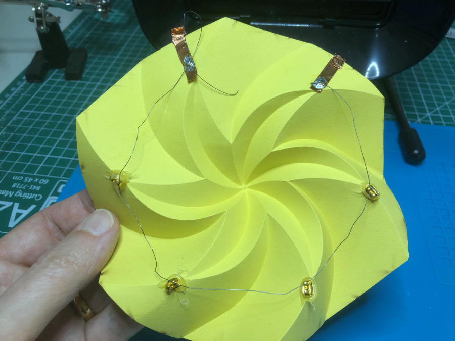
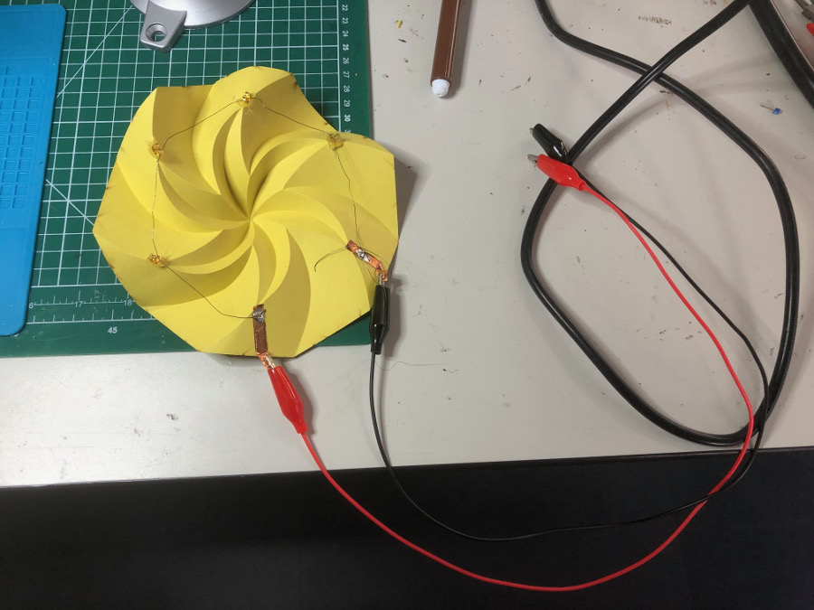
At this point it was easy to connect the set-up with a power source: a 9V Alkaline battery that had been previously tested with the multimeter to assess the voltage: 9V
The theoretical conditions to obtain the contraction of the flexinol wire are the following:
Considering that we have a wire of 1/3 of meter and resistance per meter is 70 Ohms
Current required to get to the contraction is 250mA
Voltage necessary is (70/3)*0,25 = 5,83 V
In theory, the 9V battery should be sufficently powerful to generate a 250mA current, in pratical terms the test failed.
Evolution of the concept:
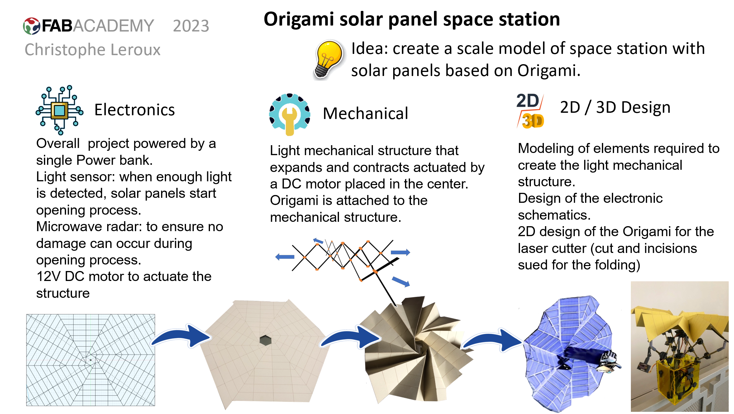
Idea: keep on working on Origami but change the project and actuators to create a small model of Origami solar panels to power a space stations

Creation of the Origami project with Fusion360:
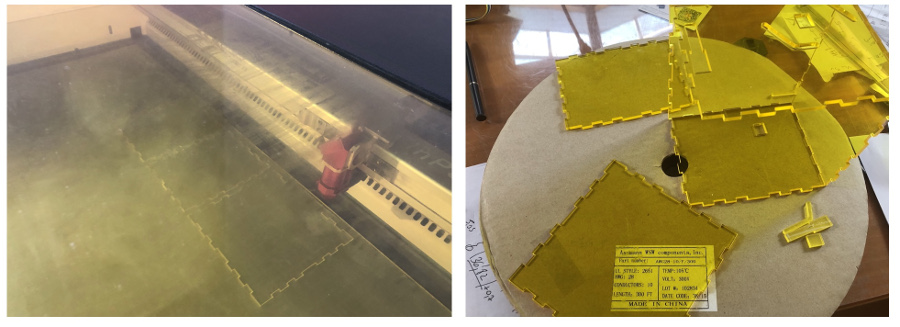
First attempt of creation of the flat Origami with the laser cutter (dimensions of the paper used: 60 x 40 cms)
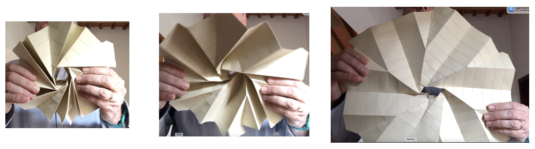
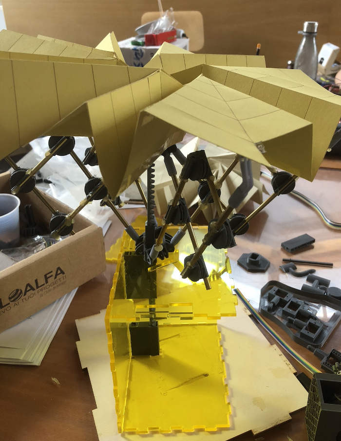
The folding of this origami is not that easy but in the end, I managed to fold it:
Overview of the Origami : from closed to fully opened:
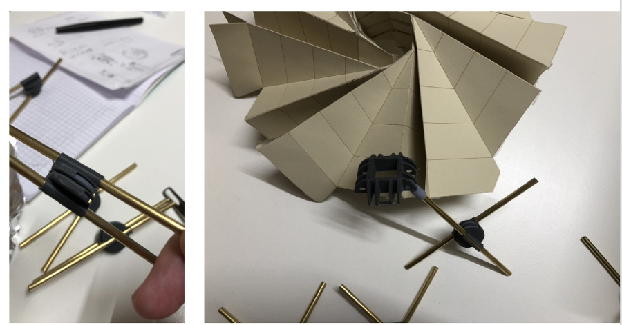
Identify best suitable structure to anchor the Origami
After quite many drawing, I came to the conclusion that the easiest and lighest structure should be inspired from the umbrella.
With the difference that the overall structure would not be circular but "a Cross" that should be more than enough to support deploymemnt and closure of our solar panel Origami.
One of the constraints that I imposed myself was to avoid the use of bolts and threaded rods. In the end, the blue sky solution if I successfull will consist in custom made components and 4mm diameter brass metal rods.
Mechanical part
Origami is made of paper in the current stage
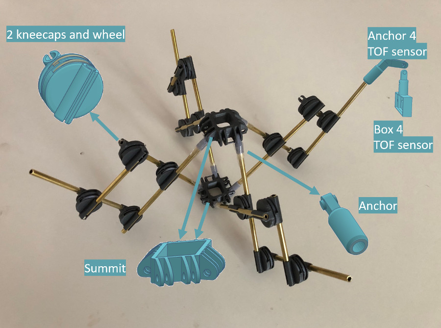
The solar panel /origami is going to be fixed on a variable geometry structure made of 3D printed components used to connect lightweight aluminum rods
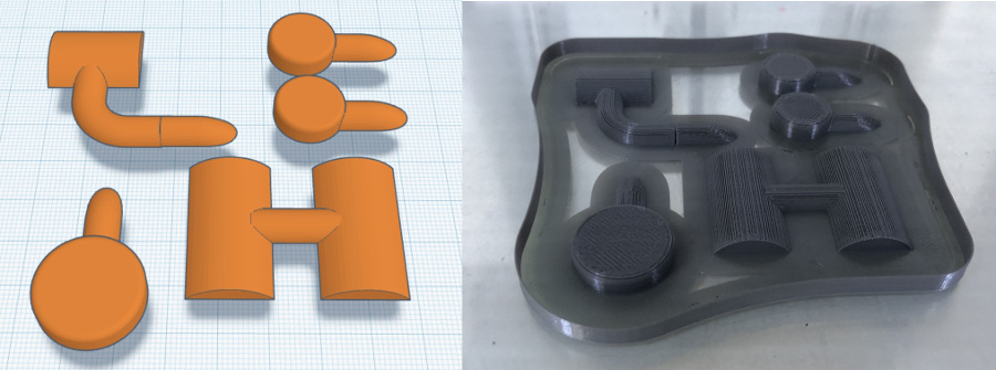
To assemble this structure, following components have been modelled and 3D printed:
STL files download
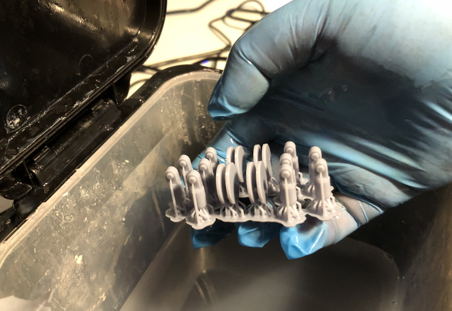
Except for the Anchor and wheel that have been printed in resin, all the other components have been printed in PLA using the Ultimaked 3 printer available.
The selection of the resin for the wheel and the anchor is driven by the need to precision and higher resolution compared to PLA.
Freshly resin-printed anchors and wheels:
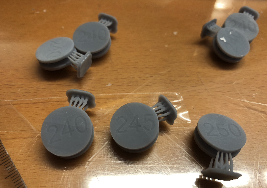
Note: in anticipation of the fine tuning activities, three types of wheel have been prepared.
The wheels prepared are 2.40, 2.45, 2.50 mm height
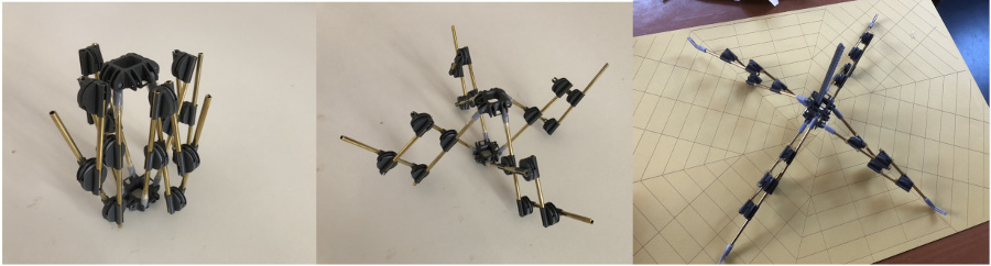
Start of the assembly of the structure:
The tests performed during the assembly processed have shown that the 2.40 mm height wheel was performing best and ensured a smooth rotation.
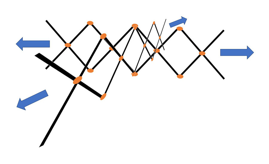
Overview of the mechanical structure in 3 states: closed, "half-opened" and fully-opened:
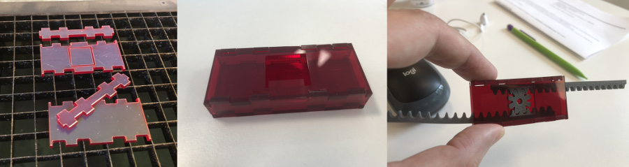
Now it comes to the design of an actuation solution for this mechanical structure.
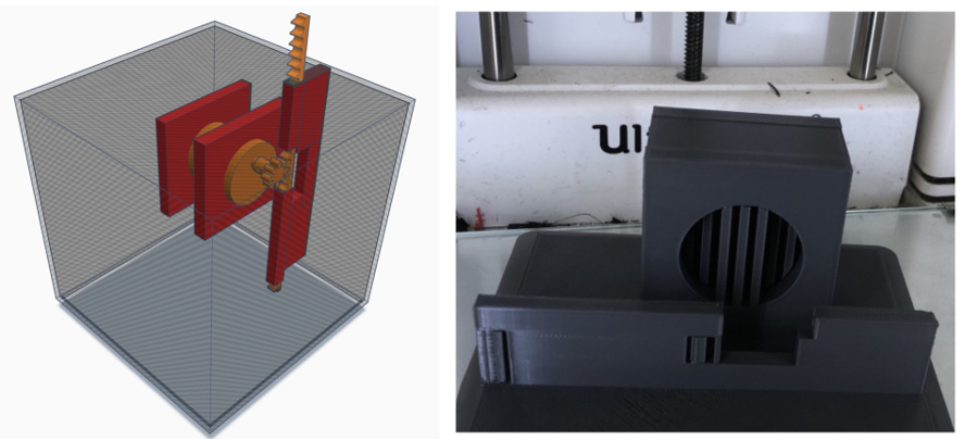
My first iteration conssisted in building this plexiglas box that was hosting 2 racks and one pinion system.
The advantage of this system is that with a linear displacement of X in one direction, we also obtain a displacement of X in the opposite direction which doubles the spacing.
In spite of this advantage, after some tests I realized that the space required to locate this mechanism in the center of the mechanism was too tiny. I had to find another solution.
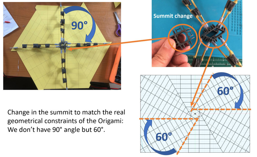
After manual integration of the components (no DC motor yet), the prelimianry test of interworking between the mechanical structure and the origami revealed a serious design problem.
Indeed, the angle between the two mechanical parts must not be 90 degrees but 60 degrees.
Rack and pinion stl files:
Electronical part:
Overview of the architecture of the electronical part of the project:
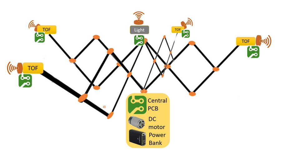
Constraints: to stick as much as possibile to the rule consisting in delivering a "clean structure", the electric wires will pass inside the tubes of the structure.
The tubes used to build the structure have a diameter of 4 mms that is pretty tiny considering that we have 4 wires to pass from each TOF to the central PCB
We will also have to pass 3 wires from for the Light sensor (located in the center of the Origami) to reach the central PCB.
The overall electronical assets consist of: one central PBC that will be communicating with 1 photoresistance PCB, 4 TOF PCBs abd one PCB for the DC motor control.
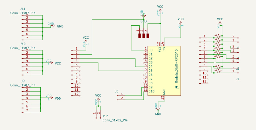
Main PCB, overview of the main PCB Scheme created with KiCad:
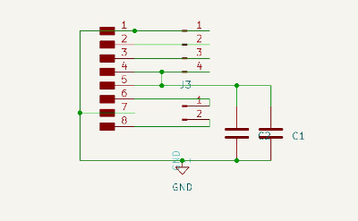
PCB for motor control: overview of the Scheme created with KiCad:
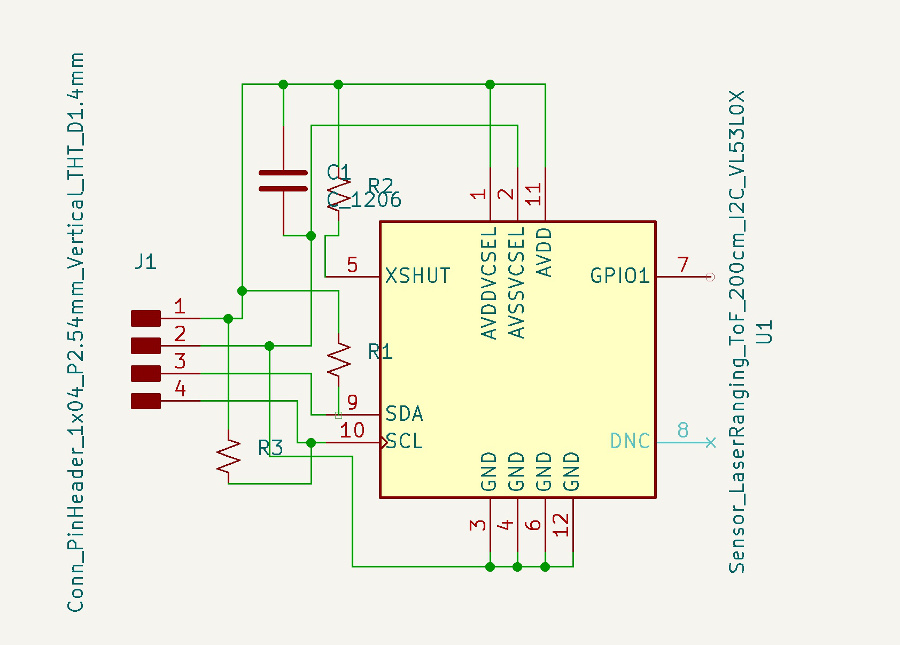
TOF PCB: overview of the Scheme created with KiCad:
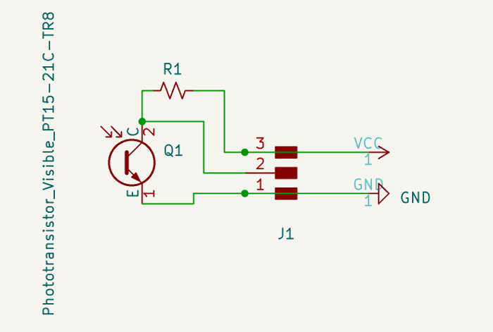
Photoresistance PCB: overview of the Scheme created with KiCad
KiCad project files:
Main PCB part:
DC motor PCB part:
Photoresistance part:
TOF part:
The motor used is a DC motor available in the lab with following characteristics: DC motor with reduction (9-24V), 5 volt power supply motor.
This motor is controlled with Pulse-width modulation (PWM) pulses to slow down the rotation of the axis
To handle more than one TOF sensor, we were forced to use an I2C MUX (TCA9548A)
The reference if the TOF sensor used is VL5310x manufactured by ST Microelectronics
Technical sheet vl53l8Software part:
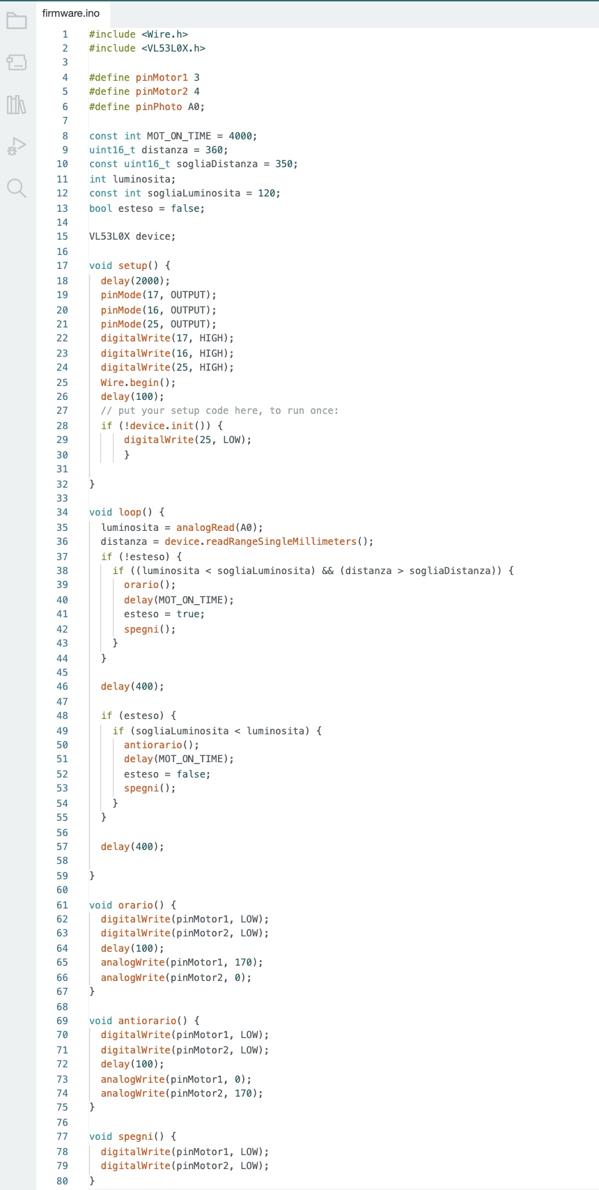
Overview of the code written using Arduino IDE:
Sensors integration into the prototype:
From left to right:
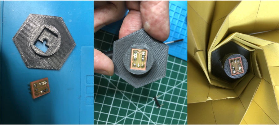
As far as the TOF sensor is concerned, the commercial sensor that we were forced to use (considering the failure in the two tentatives to build and operate the PCB built in-house) was integrated into a specific enclosure that we 3D printed.
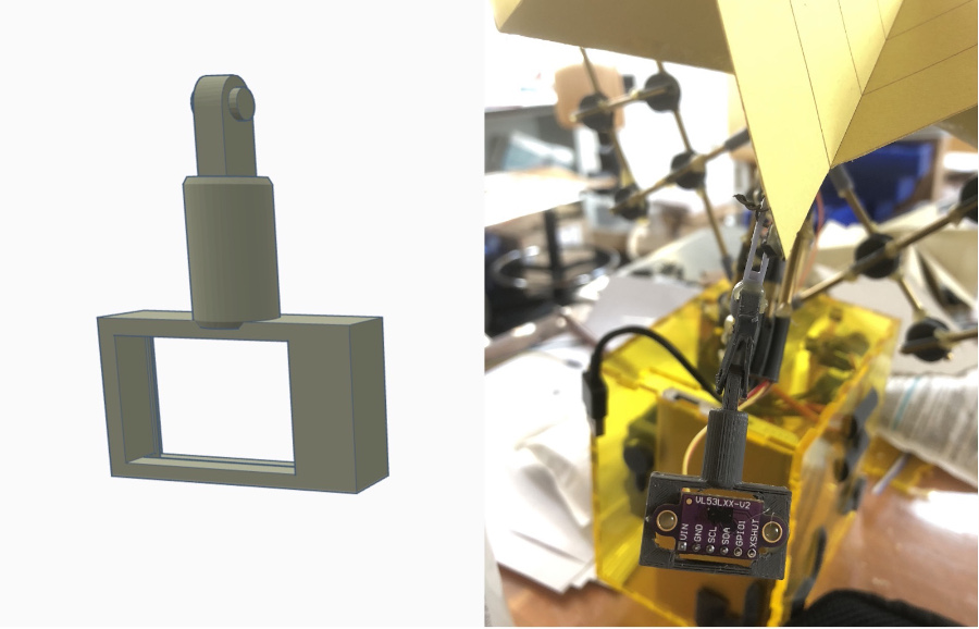
First test of full integration: engine, mechnical, electronical and SW
Enclosure for the motor and electronic components:
To limit the time of production that is pretty long with 3D printing, I opted for the preparation of a plexiglass enclosure in which will the electronic cards, the engine and the power bank will be placed.
Cut of the different components of the enclosure with the laser cutter:
Enclosure assembly, work in progress:
View of the components created:
This rack and pinion combination is the simplest linear actuator I have found to serve my needs. The rotation of a shaft powered by the DC motor is converted to linear motion.
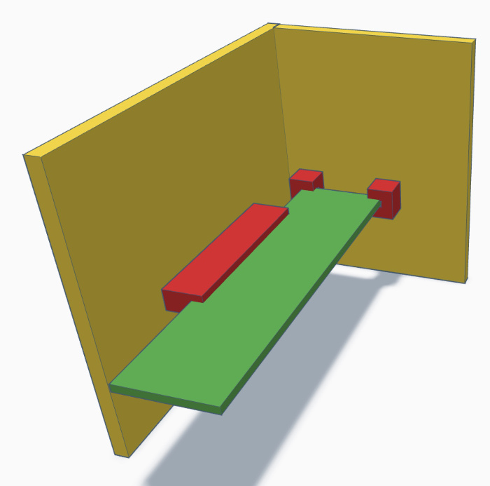
View of the components created to maintain the main PCB (in green) in place using the red elements that will be glued on the plexiglas box (in yellow).
Last but not least, some decorative elements have been created to give a slightly more "spatial" touch to the enclosure.
Overview of the final results of the project:
One slide presentation of my final project:
Video of presentation of my final project:
Conclusion and next steps:
The final project as I presented it on June 14, 2023 is perfectly functional and the the integration between the different components is complete.
The light and TOF sensors fulfill their role perfectly and ensure an opening of the Origami when the light detected is sufficient, the same way the TOF sensors prevent opening when an obstacle is detected near the ends of the Origami.
I have come back to the pertinent observation of Prof. Neil Gershenfeld during the presentation on June 14th. In the the video available on this page it may seem that the opening and closing range of the Origami solar panel is a bit limited.
During the first use, the amplitude is good but over time, we actually begin to notice a reduction in the amplitude which is very probably linked to a loss of energy in the connection between the motor, the mechanical structure and origami
This is one of the top items in the list of things that should be investigated in a next iteration of the project
Research
Relevant links:
- Journal of experiemental botany. Flower opening and closure: a review
- Flexinol test
- Flexinol based actuator
- Flexinol test
- Patch 0,15mm flexinol
- Paper tubes make stiff origami structures
- Origami and Geometric Constructions by Robert J. Lang
Botany, nature mechanism replication:
Flexinol:
Origami: