Week 13:Networking and Communications.
Assignment Activities
1.Group Assignment.
.send a message between two projects
2.Individual Assignment.
.design, build, and connect wired or wireless node(s)
with network or bus addresses
Group Assignment.
The group Assignment Page
Individual Assignment.
In This week 13 of Networking and Communications I Thought it to be quite easy because in week 4 I have used communication protocol which was in bluetooth mode but the thing was that communication was between my MCU and my device(Telephone) I used to control my board using telephone through bluetooth communication, However in this week I found that it's bit different from what I was thinking rather was communication between boards, for this I conducted the research about communication between the boards.
Firstly, networking is the practice of connecting computing devices together to enable communication and data exchange between them.
Secondly, Communication is a way of exchanging an imformation or message from one place to another or from a device 1 to device2
point to point.
For me in this week I used Wireless (bluetooth) as my Communication Protocol to link two boards one is my board and other is commercial board.
Bluetooth is universal for short-range wireless voice and data communication. It is a Wireless Personal Area Network (WPAN) technology and is used for exchanging data over smaller distances.
Bluetooth simply follows the principle of transmitting and receiving data using radio waves.
The reason why I used those two boards was that they consume low voltage and both have regulators and their consumption power can be obtained in USB Port of the machine and this could be so much easier to me in their establishment.
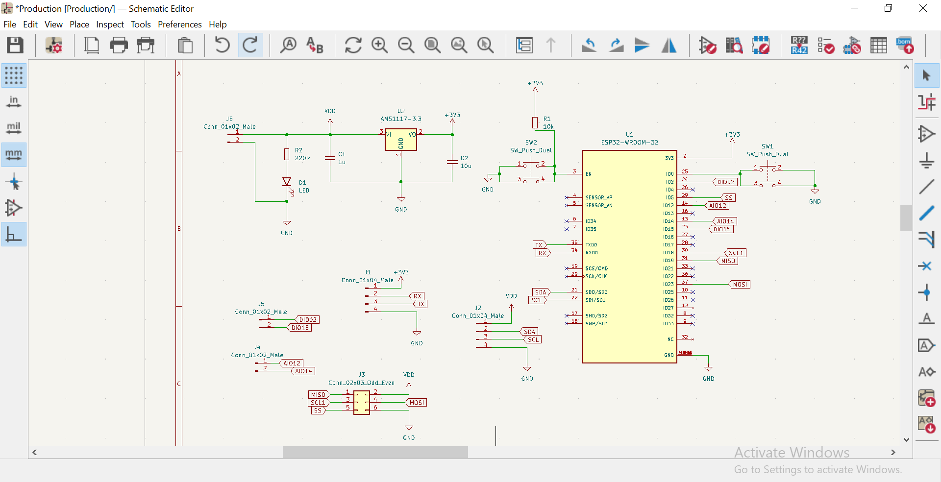
In this Week I used the same board with the one I used in the previous weeks which are (both Output and Input devices),For the first time in it's schematic and PCB editor design I considered All of those connectors that could serve in all needs we have.
Boards I used.
Below is it's schematic diagram in KICAD Software.
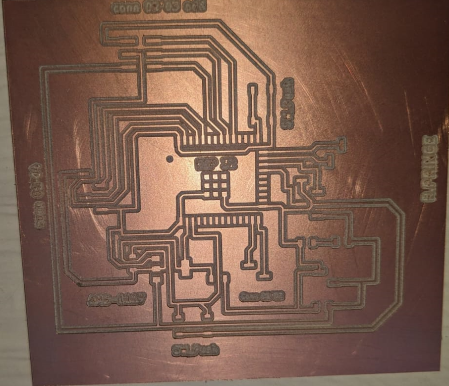
Below is it's PCB editor design in KICAD Software.

And after Milling on machine.
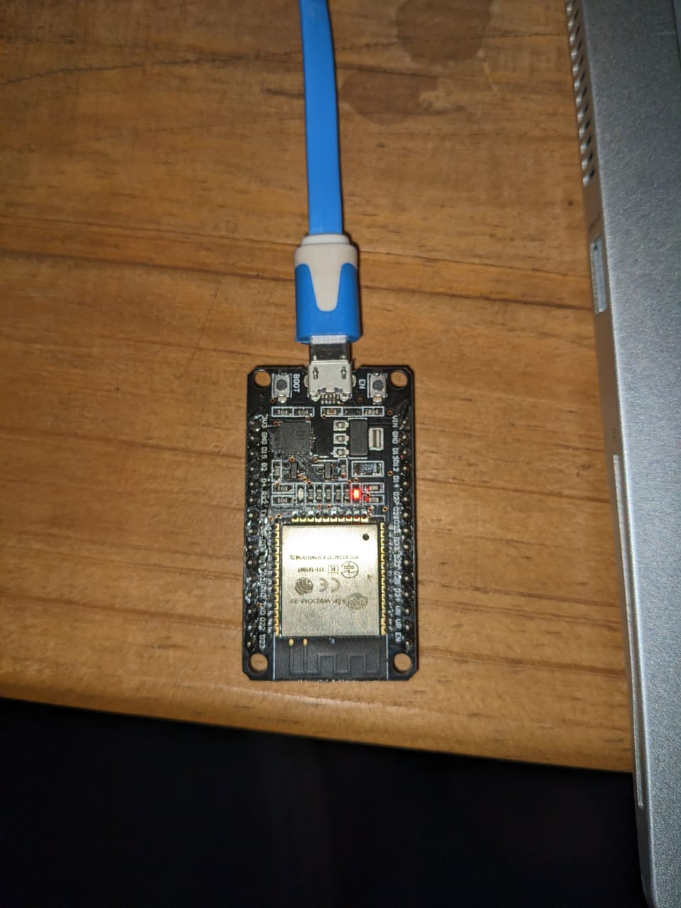
Then After Soldering The board

Mainly All the steps to create my board are stated in Week_9 of output devices. Where I designed the board and put all necessary connectors that I will use in some other weeks ahead.
Another Board I used is development ESP32 board which also has ESP32 as it's MCU.
Communication Protocol.
Communication Protocol: is a system of rules that allows two or more entities of a communications system to transmit information via any kind of variation of a physical quantity.
Communication has 2 main types which are one-way and two-way Communication Protocol, and For me I used 2-way communication Protocol in the transimission of Data.
a two-way communication protocol is a method for transmitting data between two devices, where both devices can send and receive data. The specific protocol used depends on the requirements of the application, including factors such as data transfer speed, distance, and reliability.
Another reason to use ESP32 board is that it has many communication protocols that can be used in transmitting the message from the master to slave. i can use SPI(Serial Peripheral Interface),UART(Universal Asynchronous Receiver-Transmitter),I2C(Inter-Integrated Circuit),and Also Bluetooth which I used in this Week.
For me I used bluetooth as my communication Protocol.
Bluetooth is a short-range wireless communication technology that allows devices such as mobile phones, computers,
and peripherals to transmit data or voice wirelessly over a short distance. The purpose of Bluetooth
is to replace the cables that normally connect devices, while still keeping the communications between them secure.
for my assignment i have tried to integrate bluetooth communication where i connect between two different boards learn more
Steps I followed to Program Boards.
-
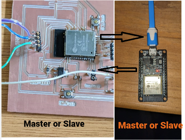
Before I connected my Board to one Laptop and the development board to another Laptop for the power supply or in order to to be on.
so as i said before I have used 2 Boards. In order to start communicating between each other, i set one as master and another one as a slave
in order to implement we need to scan mac address of the slave device so that the master device recognise the slave by addressing it for it to able to communicate each other
at first uploaded the codes that are used for scanning mac address of the device then the following codes do the work
        void setup(void) {
          Serial.begin(115200); // starting serial terminal
          Serial.println("-----------------");
          uint8_t macBT[6]; // array variable holding the mac address to store the
          esp_read_mac(macBT, ESP_MAC_BT);
        }

        void loop() {
          uint8_t macBT[6];
          esp_read_mac(macBT, ESP_MAC_BT);
          Serial.printf("%02X:%02X:%02X:%02X:%02X:%02X\r\n", macBT[0], macBT[1], macBT[2], macBT[3], macBT[4], macBT[5]);
          delay(10000);
        }
-
i have selected the the shown address and copied them aside and use it as i talked about it above

then under the highlighted variable "address[6]" it is where i included the mac address of the esp32 (slave)

so for the following codes below where it is mentioned as master
Master
          #include "BluetoothSerial.h"

          #define USE_NAME // Comment this to use MAC address instead of a slaveName
          const char *pin = "1234"; // Change this to reflect the pin expected by the real slave BT device

          #if !defined(CONFIG_BT_SPP_ENABLED)
          #error Serial Bluetooth not available or not enabled. It is only available for the ESP32 chip.
          #endif

          BluetoothSerial SerialBT;

          #ifdef USE_NAME
            String slaveName = "myslave"; // Change this to reflect the real name of your slave BT device
          #else
            String MACadd = "7C:9E:BD:49:4E:2A"; // This only for printing 7C:9E:BD:49:4E:2A

            uint8_t address[6]  = {0x7C, 0x9E, 0xBD, 0x49, 0x4E, 0x2A}; // Change this to reflect real MAC address of your slave BT device
          #endif

          String myName = "MasterBT";

          void setup() {
            bool connected;
            Serial.begin(115200);

            SerialBT.begin(myName, true);
            Serial.printf("The device \"%s\" started in master mode, make sure slave BT device is on!\n", myName.c_str());

            #ifndef USE_NAME
              SerialBT.setPin(pin);
              Serial.println("Using PIN");
            #endif

            // connect(address) is fast (up to 10 secs max), connect(slaveName) is slow (up to 30 secs max) as it needs
            // to resolve slaveName to address first, but it allows to connect to different devices with the same name.
            // Set CoreDebugLevel to Info to view devices Bluetooth address and device names
            #ifdef USE_NAME
              connected = SerialBT.connect(slaveName);
              Serial.printf("Connecting to slave BT device named \"%s\"\n", slaveName.c_str());
            #else
              connected = SerialBT.connect(address);
              Serial.print("Connecting to slave BT device with MAC "); Serial.println(MACadd);
            #endif

            if(connected) {
              Serial.println("Connected Successfully!");
            } else {
              while(!SerialBT.connected(10000)) {
                Serial.println("Failed to connect. Make sure remote device is available and in range, then restart app.");
              }
            }
            // Disconnect() may take up to 10 secs max
            if (SerialBT.disconnect()) {
              Serial.println("Disconnected Successfully!");
            }
            // This would reconnect to the slaveName(will use address, if resolved) or address used with connect(slaveName/address).
            SerialBT.connect();
            if(connected) {
              Serial.println("Reconnected Successfully!");
            } else {
              while(!SerialBT.connected(10000)) {
                Serial.println("Failed to reconnect. Make sure remote device is available and in range, then restart app.");
              }
            }
          }

          void loop() {
            if (Serial.available()) {
              SerialBT.write(Serial.read());
            }
            if (SerialBT.available()) {
              Serial.write(SerialBT.read());
            }
            delay(20);
          }
Slave
#include "BluetoothSerial.h"

//#define USE_PIN // Uncomment this to use PIN during pairing. The pin is specified on the line below
const char *pin = "1234"; // Change this to more secure PIN.

String device_name = "myslave";

#if !defined(CONFIG_BT_ENABLED) || !defined(CONFIG_BLUEDROID_ENABLED)
#error Bluetooth is not enabled! Please run `make menuconfig` to and enable it
#endif

#if !defined(CONFIG_BT_SPP_ENABLED)
#error Serial Bluetooth not available or not enabled. It is only available for the ESP32 chip.
#endif

BluetoothSerial SerialBT;

void setup() {
  Serial.begin(115200);
  SerialBT.begin(device_name); //Bluetooth device name
  Serial.printf("The device with name \"%s\" is started.\nNow you can pair it with Bluetooth!\n", device_name.c_str());
  //Serial.printf("The device with name \"%s\" and MAC address %s is started.\nNow you can pair it with Bluetooth!\n", device_name.c_str(), SerialBT.getMacString()); // Use this after the MAC method is implemented
  #ifdef USE_PIN
    SerialBT.setPin(pin);
    Serial.println("Using PIN");
  #endif
}

void loop() {
  if (Serial.available()) {
    SerialBT.write(Serial.read());
  }
  if (SerialBT.available()) {
    Serial.write(SerialBT.read());
  }
  delay(20);
}
for the part of master this is initialisation and declaration
      #include "BluetoothSerial.h"

      #define USE_NAME // Comment this to use MAC address instead of a slaveName
      const char *pin = "1234"; // Change this to reflect the pin expected by the real slave BT device

      #if !defined(CONFIG_BT_SPP_ENABLED)
      #error Serial Bluetooth not available or not enabled. It is only available for the ESP32 chip.
      #endif

      BluetoothSerial SerialBT;

      #ifdef USE_NAME
        String slaveName = "myslave"; // Change this to reflect the real name of your slave BT device
      #else
        String MACadd = "7C:9E:BD:49:4E:2A"; // This only for printing 7C:9E:BD:49:4E:2A

        uint8_t address[6]  = {0x7C, 0x9E, 0xBD, 0x49, 0x4E, 0x2A}; // Change this to reflect real MAC address of your slave BT device
      #endif

      String myName = "MasterBT";
for the first line it is included with a library of bluetooth which is able to open bluetooth terminal for both configurations
the above sketches are for master controller,we define the name of slave side String slaveName = "myslave";this is the name of slave device String myName = "MasterBT"; we set this name master name as "MasterBT",and also to be able to communicate between two devices we set the mac address of slave device to master so it recognise the slave String MACadd = "7C:9E:BD:49:4E:2A";
in void setup we start the bluetooth terminal so it start operating, and also start the serial terminal
and we configure the connection master to slave
      void setup() {
        bool connected;
        Serial.begin(115200);

        SerialBT.begin(myName, true);
        Serial.printf("The device \"%s\" started in master mode, make sure slave BT device is on!\n", myName.c_str());

        #ifndef USE_NAME
          SerialBT.setPin(pin);
          Serial.println("Using PIN");
        #endif

        // connect(address) is fast (up to 10 secs max), connect(slaveName) is slow (up to 30 secs max) as it needs
        // to resolve slaveName to address first, but it allows to connect to different devices with the same name.
        // Set CoreDebugLevel to Info to view devices Bluetooth address and device names
        #ifdef USE_NAME
          connected = SerialBT.connect(slaveName);
          Serial.printf("Connecting to slave BT device named \"%s\"\n", slaveName.c_str());
        #else
          connected = SerialBT.connect(address);
          Serial.print("Connecting to slave BT device with MAC "); Serial.println(MACadd);
        #endif

        if(connected) {
          Serial.println("Connected Successfully!");
        } else {
          while(!SerialBT.connected(10000)) {
            Serial.println("Failed to connect. Make sure remote device is available and in range, then restart app.");
          }
        }
        // Disconnect() may take up to 10 secs max
        if (SerialBT.disconnect()) {
          Serial.println("Disconnected Successfully!");
        }
        // This would reconnect to the slaveName(will use address, if resolved) or address used with connect(slaveName/address).
        SerialBT.connect();
        if(connected) {
          Serial.println("Reconnected Successfully!");
        } else {
          while(!SerialBT.connected(10000)) {
            Serial.println("Failed to reconnect. Make sure remote device is available and in range, then restart app.");
          }
        }
      }
then in the void loop we set and communicate between two boards (esp32)
Hello Shot While Working.