Output Devices
Assignment to be done:
1.Group Assignment: Measure the power consumption of an output device
To be found here
2. Individual Assignment:Add an output device to a microcontroller board you’ve designed and program it to do something.
1. Reflection on what I learned from Group Assignment
In our group we controlled the servo motor as our output device with ESP32 .
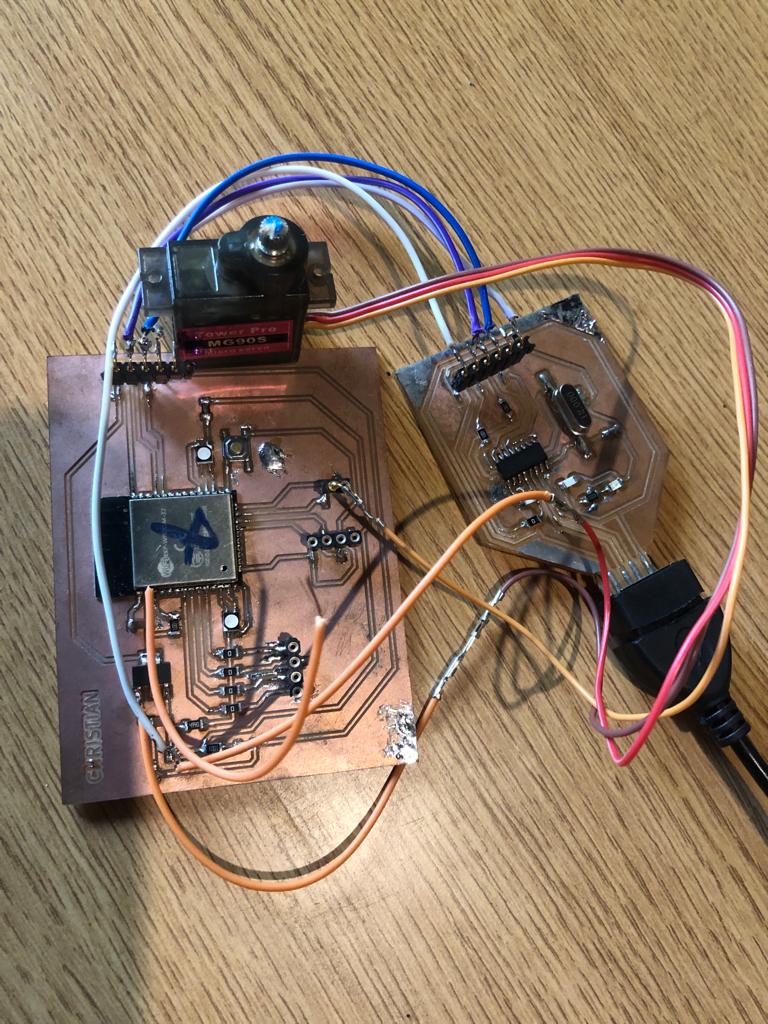
How to determine the power consumption of ouput device
They are many factors to consider when determining the power consumption of an output device connected to a microcontroller.
Among them there are:
1. To measure the voltage crossing the device and the current passing throught it:The voltage and current ratings of the output device are important as they determine the amount of power it can consume.
Normally to measure the voltage we used a Multimeter that is calbrated in the range of voltages. The measured value is recorded some where and the next is to measure the current where the multimeter is calbrated into current range as well as to change the positive probe of multimeter to the current port.

Note that when measuring the voltage, the measuring device(multimeter) is in parallel with the device to be measured while for the current a multimeter is placed in series with it. When the measured values(both current and voltage) are ready, the following formule is used to determine the power consumption of our output device.
Power Consumption (Watts) = Voltage (Volts) x Current (Amps)
The following are the measured values of both voltage and current
1. Voltage= 4.88V
2. Current= 0.044A
Then the power consumption= (4.88*0.044)W = 0.21472W = 214.72mW
2. The power consumption of a device also depends on Duty Cycle: The duty cycle of the output device is the amount of time it spends on compared to the total time. The higher the duty cycle, the higher the power consumption.
3. It also depends on Frequency: The frequency at which the output device switches on and off also affects its power consumption. Higher switching frequencies result in higher power consumption.
4. And Load: The load connected to the output device can affect its power consumption. A heavy load will draw more current and result in higher power consumption.
Design and Fabrication Process
I have designed the ESP32 microcontroller board and I programed it to display something on OLED as a part of my final project.
What is development board?
A development board is essentially a printed circuit board with circuitry and hardware for experimenting with specific microcontrollers, microprocessors, or other complex integrated circuits (IC).
A development board is a circuit board that is designed to help developers prototype, test and develop new hardware or software projects. Development boards typically come with a range of features and components such as microprocessors, memory, input/output interfaces, sensors, and communication interfaces that allow developers to experiment with and test various configurations and functionalities. Development boards can be used for a wide range of applications, from designing and testing embedded systems for Internet of Things (IoT) applications to developing new firmware and software for microcontrollers and other electronic devices. They are typically designed to be easy to use and configure, with support for common programming languages and development tools, making them an ideal tool for hobbyists, students, and professionals alike.
Specifically, an IoT development board includes:
A programming interface to program the microcontroller from a computer. A power circuit used to provide stable DC power to the microcontroller. Input components: buttons, switches, etc. Output components such as LEDs. Various I/O pins used for compatibility with sensors, motors, screens, and any other components.
There are three devkit categories:
1.Microcontroller - based boards comprised of a small computer, usually built with CMOS processes. These are primarily used in implants, office machines, power tools, and automotive control systems.
2.System-on-Chip SoC boards have more system components integrated into the chip and have memory, audio receivers, PCI, SATA, and USB communication abilities in addition to a microprocessor. Additional electronic components and circuits are the only things required–fewer additional ICs. They allow for more miniaturization and higher processing speeds with less microchip power. This is all at the cost of specialization and development time.
3.Single Board Computers (SBCs) contain all the features of a computer on a single device, including I/O ports, microprocessors, and memory. SBCs are usually larger but are more capable and do not need to rely on expansion slots for additional peripheral capabilities. By refering from Here
Steps to develop a development board
Developing a development board requires a comprehensive understanding of the target microcontroller, programming languages, hardware design, and circuitry. Below are some steps to develop a development board:
- 1. The first step is to identify the microcontroller that you want to use on the development board. Select a microcontroller that is suitable for your project requirements.
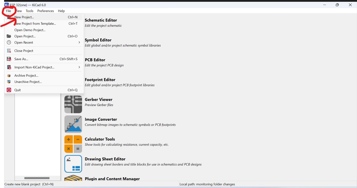
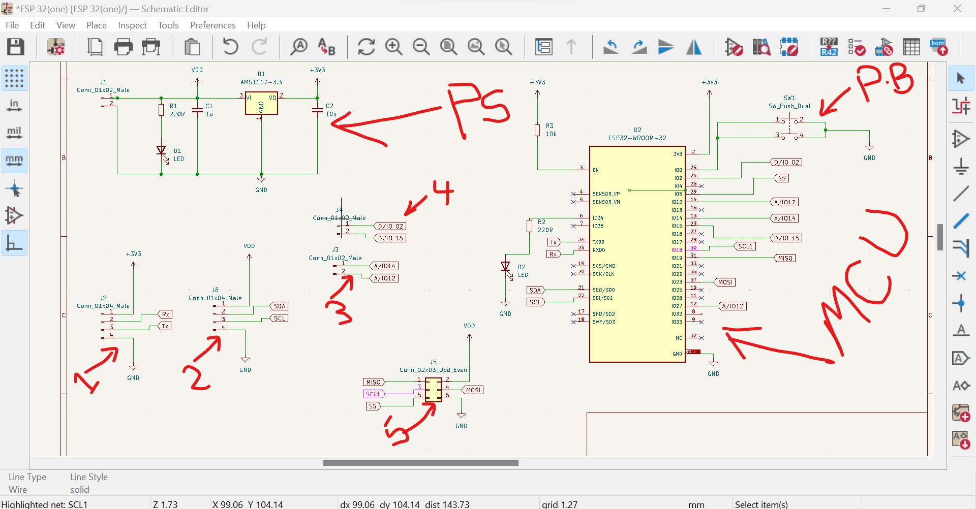
- 2. After identifying the microcontroller, create a schematic design for the development board.
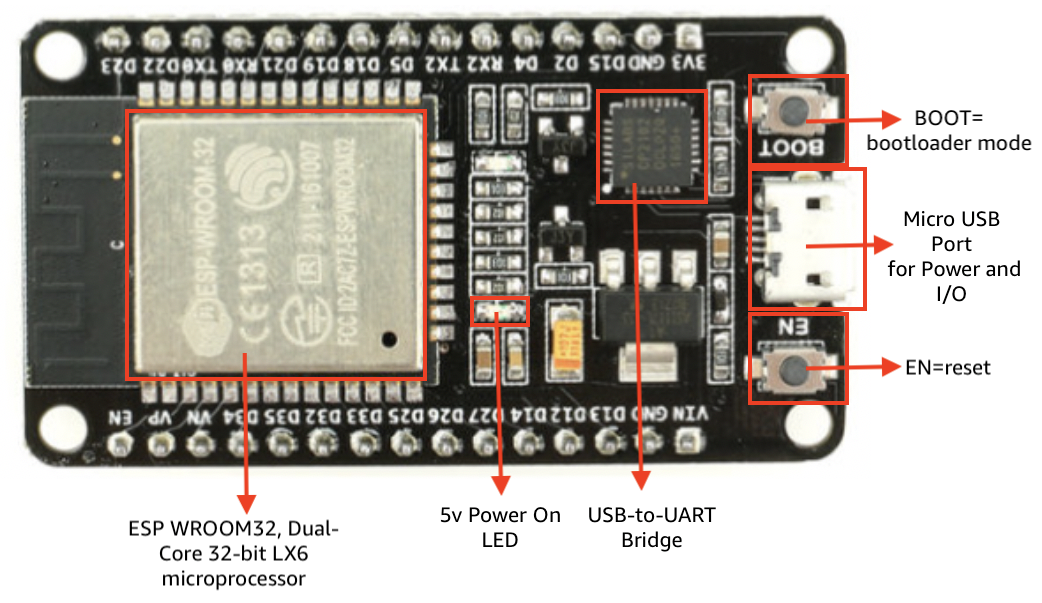
ESP32 Board Guide
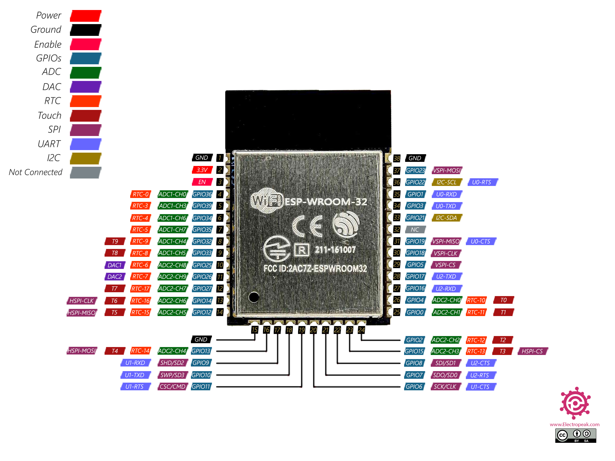
Reference from https://electropeak.com/learn/full-guide-to-esp32-pinout-reference-what-gpio-pins-should-we-use/(for Full Guide to ESP32 Pinout)
The ESP32 supports three types of I/O modes with each GPIO Pin: Digital, Analog and Internal Sensors
Analog: Used to send/receive analog data using the following functions:
# examples based on Arduino IDE
analogRead();
analogWrite();
Digital: Used to send/receive digital data using the following functions:
# examples based on Arduino IDE
digitalRead();
digitalWrite();
Internal Sensors: This mode allows us to fetch internal sensor data from the ESP32 itself. The three sensors available are as follows:
Internal Temperature Sensor
Hall Effect Sensor
Touch Sensor
These sensors can be accessed by the following functions:
# examples based on Arduino IDE
temprature_sens_read()
hallRead()
touchRead()
reference from here
The schematic design includes the power supply circuit, crystal oscillator, reset circuit, programming and debugging interfaces, and other essential components as shown in the diagram below: - 3. Once the schematic design is complete, the next step is to create a PCB layout design for the development board.
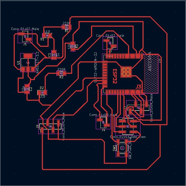
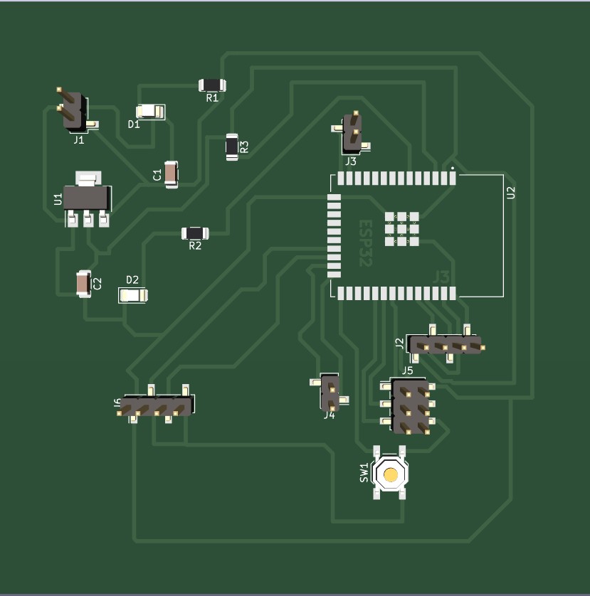
The layout design includes placing the components on the board, routing the traces, and ensuring proper clearance and alignment. - 4. Prototype the development board to ensure that it works as expected. Verify the board's functionality by programming the microcontroller and testing its various features.
- 5. After completing the prototyping phase, proceed to the production phase. Fabricate the PCBs, assemble the components, and test the final product to ensure that it meets the required specifications.
- 6. Programming and Debugging: The development board requires a software toolchain, including a compiler, linker, and programmer, to program and debug the microcontroller. Ensure that the software toolchain is compatible with the microcontroller and the development board.
- 1. Choose the output device that you want to interface with the microcontroller. Examples of output devices include LEDs, LCD displays, motors,relays, etc
- 2. Choose the interface method: Decide how you want to interface the output device with the microcontroller. This could be through digital signals, analog signals, or communication protocols such as I2C, SPI, or UART.
- 3. Connect the output device to the microcontroller: Connect the output device to the microcontroller using the appropriate hardware interface. This may involve connecting wires to specific pins on the microcontroller or using a specialized breakout board.
- 4. Write the code: Write the code that controls the output device. This involves configuring the microcontroller's pins and registers to generate the appropriate signals to the output device.
- 5. Test the system: Test the system to ensure that the output device responds as expected and debug any issues that arise.


According to my project requirements, I used ESP32 Microcontroller to be used.
ESP32 is a low-cost, low-power system-on-a-chip (SoC) microcontroller with integrated Wi-Fi and Bluetooth capabilities. It is designed and manufactured by Espressif Systems and is popularly used in Internet of Things (IoT) applications and projects due to its wireless connectivity and advanced features. The ESP32 features a dual-core processor, which can operate at speeds of up to 240 MHz, and includes built-in support for Wi-Fi 802.11b/g/n and Bluetooth 4.2. Additionally, it has a large number of general-purpose input/output (GPIO) pins, analog-to-digital converters (ADCs), and other peripheral interfaces, making it highly versatile and adaptable to a wide range of use cases. The ESP32 is also highly programmable and can be programmed using a variety of programming languages, including C and Python, making it accessible to developers of different skill levels and backgrounds. Overall, the ESP32 is a powerful and flexible microcontroller that is ideal for a variety of IoT and embedded applications.
Milling process of the board
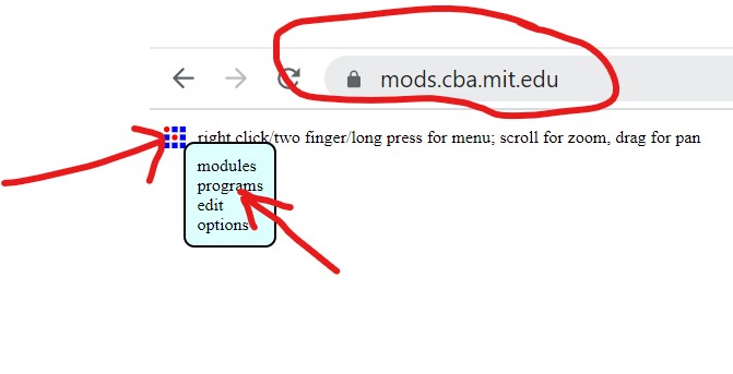

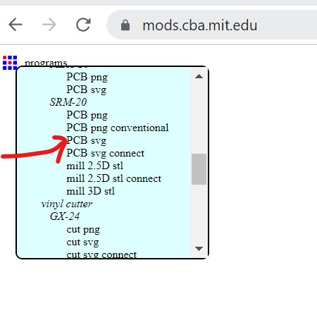
connecting input and output files and setting the X,Y,Z origins:
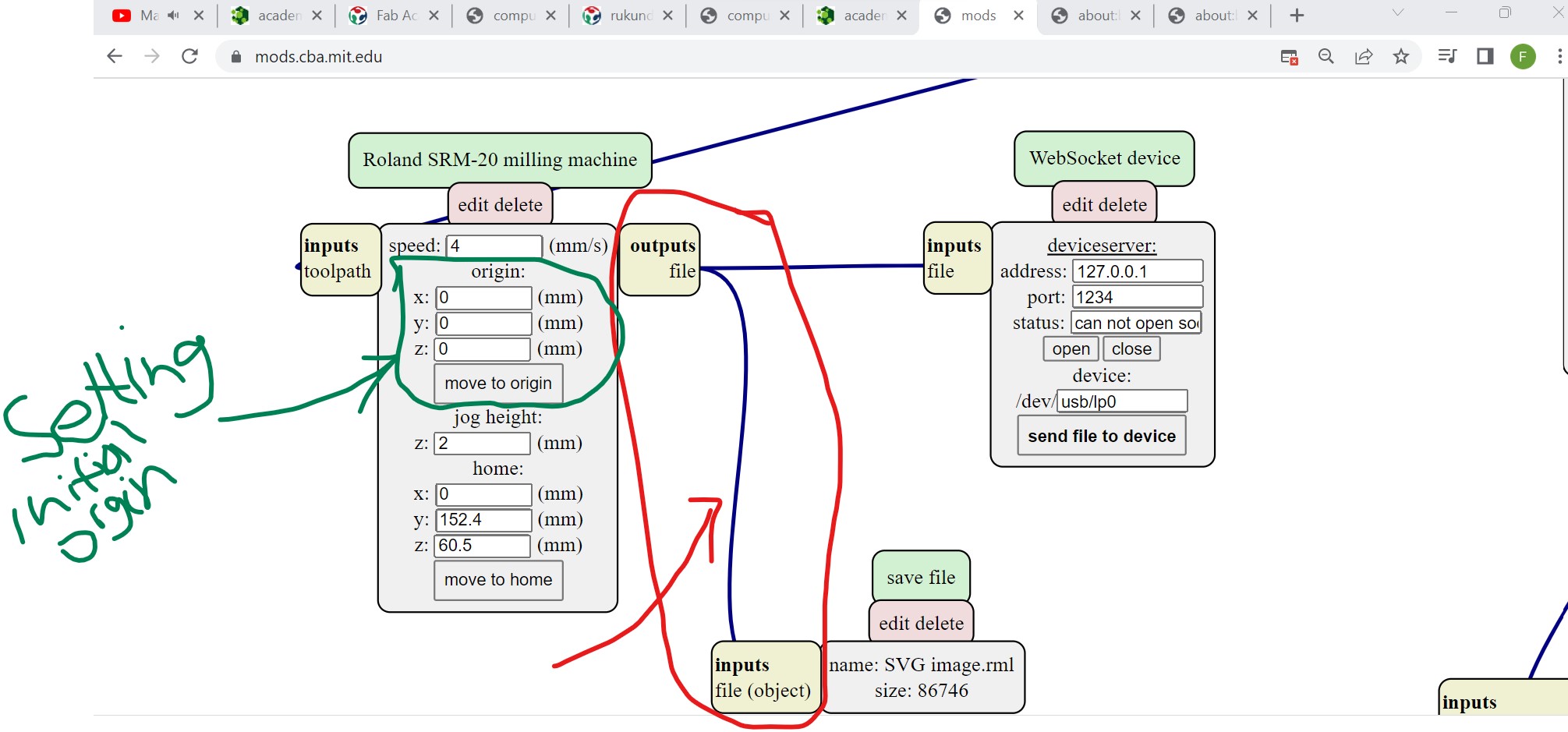 After connecting, upload the designed PCB file by clicking on select svg file, set the dpi you want to operate on(here I chose 1000) and invert the uploaded design to see where the milling machine will trace.

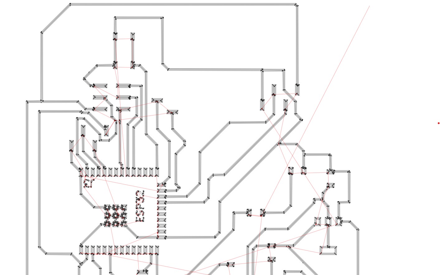
Then down here is the view of the board to be millled
PCB after Milling and cutting
Normally I made a design and fabrication of the PCB for whole works including final project.
Interfacing outpu devices to a microcontroller
The specifics of interfacing an output device with a microcontroller will depend on the particular output device and microcontroller that you are using. You should consult the datasheets and user manuals for both the output device and microcontroller to understand their capabilities and limitations.
To interface output devices to a microcontroller, you need to consider some keywords such as:
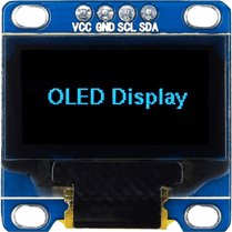
OLED (Organic Light Emitting Diode)
OLED (Organic Light Emitting Diode) is a type of display technology that uses organic compounds to emit light when an electric current is passed through them.
OLED displays are available in a range of sizes (such as 128×64, 128×32) and colors (such as white, blue, and dual-color OLEDs). Some OLED displays have an I2C interface, while others have an SPI interface.
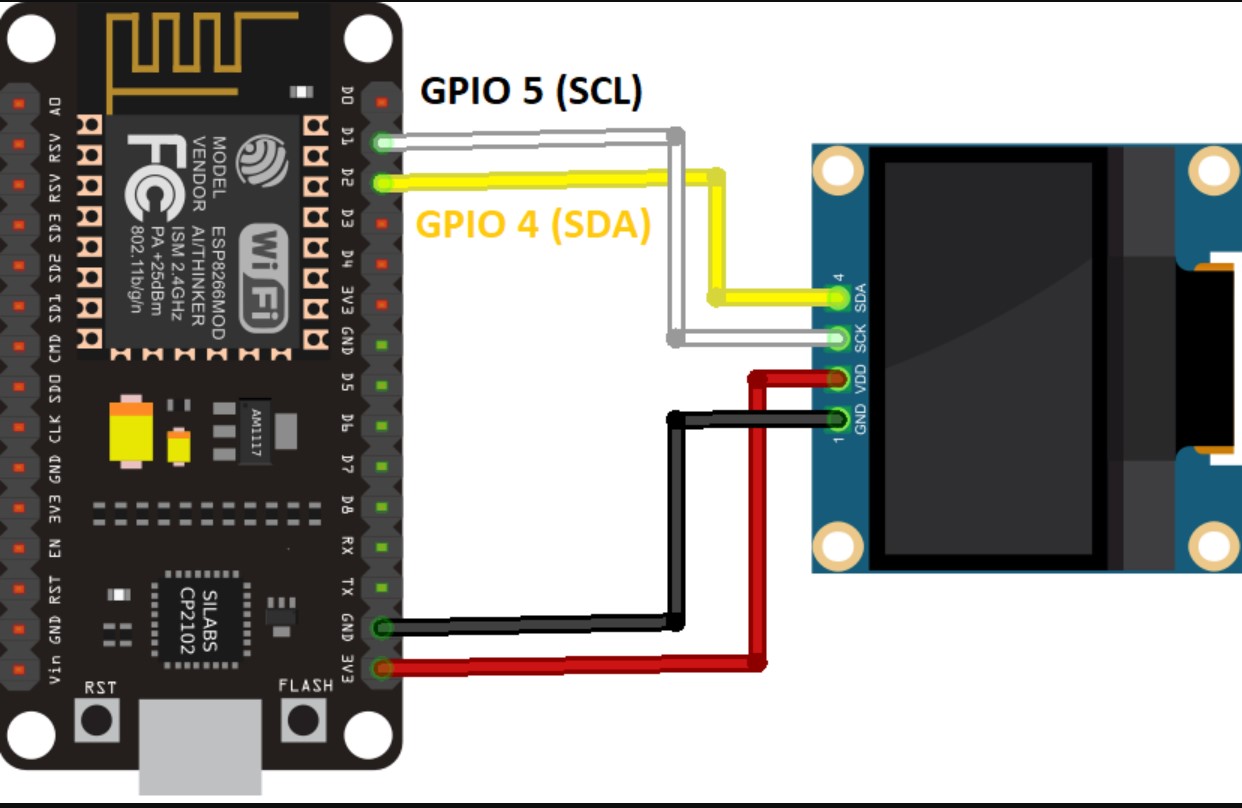
Connect the OLED display to the microcontroller using the appropriate interface. Most OLED displays use SPI or I2C communication protocols. Reference from here and https://randomnerdtutorials.com/esp32-ssd1306-oled-display-arduino-ide/

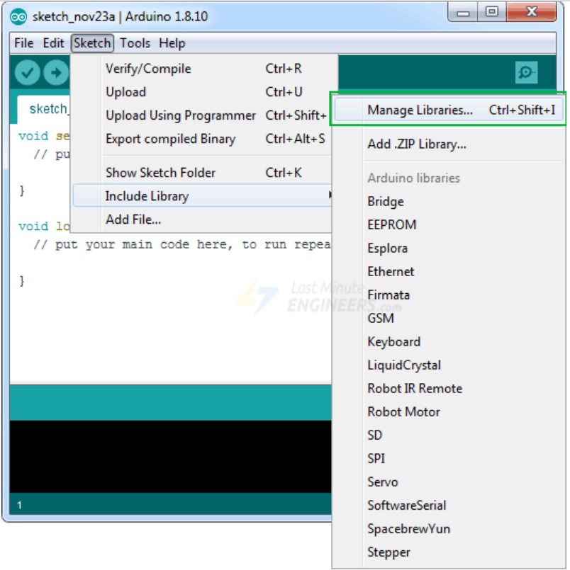
Library Installation
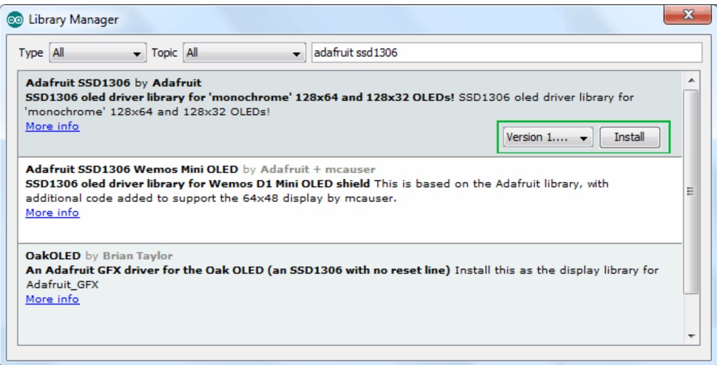
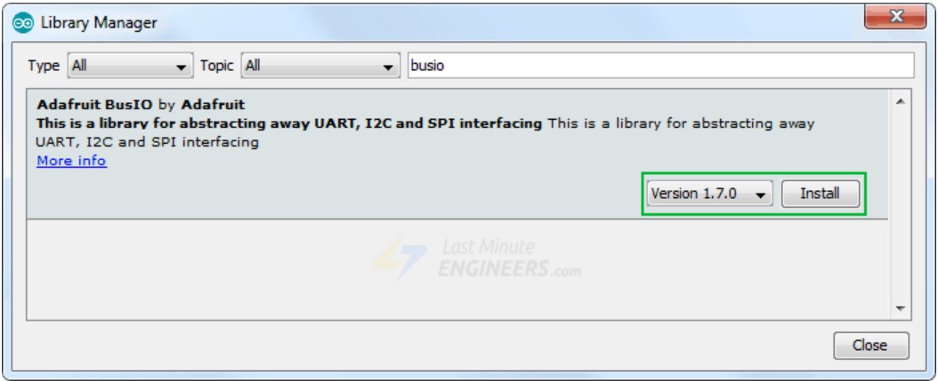
Installation of SSD1306 controller of OLED display drivers
To install the library, navigate to Sketch > Include Library > Manage Libraries… Wait for the Library Manager to download the library index and update the list of installed libraries.

Programming Process
Write the driver code: Write the driver code that controls the OLED display. This involves configuring the microcontroller's pins and registers to send data to the display over the chosen interface.
The following are the source codes used:
      #include < Wire.h>
         #include < Adafruit_GFX.h>
         #include < Adafruit_SSD1306.h>

         #define SCREEN_WIDTH 128 // OLED display width, in pixels
         #define SCREEN_HEIGHT 64 // OLED display height, in pixels

         // Declaration for an SSD1306 display connected to I2C (SDA, SCL pins)
         Adafruit_SSD1306 display(SCREEN_WIDTH, SCREEN_HEIGHT, &Wire, -1);

         void setup() {
           Serial.begin(115200);

           if(!display.begin(SSD1306_SWITCHCAPVCC, 0x3C)) { // Address 0x3D for 128x64
             Serial.println(F("SSD1306 allocation failed"));
             for(;;);
           }
           delay(2000);
           display.clearDisplay();

           display.setTextSize(4);
           display.setTextColor(WHITE);
           display.setCursor(0, 5);
           // Display static text
           display.println("Felix NYIRIGIRA");
           display.display();
           delay(100);

         }

         void loop() {
           // Scroll in various directions, pausing in-between:
           display.startscrollright(0x00, 0x0F);
           delay(2000);
           display.stopscroll();
           delay(1000);
           display.startscrollleft(0x00, 0x0F);
           delay(2000);
           display.stopscroll();
           delay(1000);
           display.startscrolldiagright(0x00, 0x07);
           delay(2000);
           display.startscrolldiagleft(0x00, 0x07);
           delay(2000);
           display.stopscroll();
           delay(1000);
         }
Details on programming
First the neccessary libraries are included:
Wire.h allows communication over the I2C bus.
Adafruit_GFX.h provides graphics functions for the display.
Adafruit_SSD1306.h is the library for the SSD1306 OLED display.
Two constants are defined:
SCREEN_WIDTH specifies the OLED display width as 128 pixels. SCREEN_HEIGHT specifies the OLED display height as 64 pixels.
The setup() function is called once at the start:
Serial communication is initialized with a baud rate of 115200.
The display is initialized using display.begin() function, and if the initialization fails, an error message is printed.
A delay of 2 seconds is added to allow time for the display to initialize.
The display is cleared using display.clearDisplay().
Text settings are configured with display.setTextSize(), display.setTextColor(), and display.setCursor().
The text "Felix NYIRIGIRA" is printed on the display using display.println().
The display is updated using display.display(), and a delay of 100 milliseconds is added.
The loop() function is called repeatedly:
Various scrolling effects are demonstrated using the display's scroll functions (display.startscrollright(), display.stopscroll()
Challenges faced
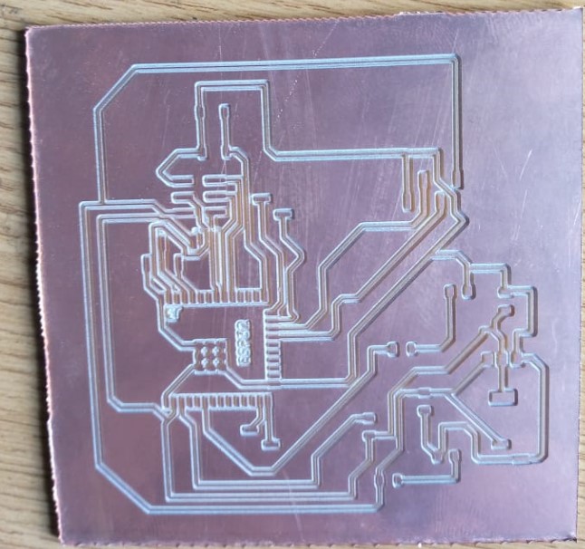
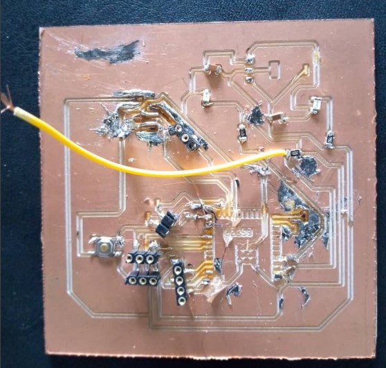
The big challenge I faced during this week is that while milling, the traces's width came very thin and was not easy to solder the components because the copper was removed very often which resulted to loose connection and as they are very thin, when I solder the soldering tin tends to create unwanted joints which cause the short circuit.
Because of these, the board was completely damaged as shown with the following image and decided to mill the new one.

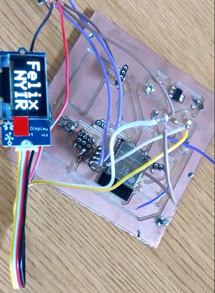
Below video is of controlling OLED using ESP32 uploaded on youtube.
Other challenge faced before I got the final result: As I wanted to use OLED on ESP32 output and it need I2C protocal, unfortunately when I started connecting it I noticed that I chose the wrong pins of esp32 for I2C!!! what I did, I connected the small wires from I2C pins(SCL&SDA) to OLED. An other problem I faced is that when I finished I noticed that there is no reset button!! I also arranged by connecting a small wire from pull up resistor and touch it on esp32 body when reset is needed.As consequency of these arrangement, The board is consisting of a lot of wires which makes the easthetics(layout) of my work to be poor!!!!
All those works(designs) done have been saved as files and they can be accessed and downloaded as a whole zipped folder via here
NAVIGATION
USEFUL LINKS FOR MORE KNOWLEDGE
https://randomnerdtutorials.com/ https://www.w3schools.com/java/java_intro.asp https://www.w3schools.com/html/default.asp https://developer.mozilla.org/en-US/docs/Web/HTML/Element/brAddress
2023 All Rights Reserved. Designed by Felix NYIRIGIRA