Computer Controlled Machining
Assignment to be done:
1.Group Assignment
.Complete your lab’s safety training
.Test runout, alignment, fixturing, speeds, feeds, materials and toolpaths for your machine
.Document your work to the group work page and reflect on your individual page what you learned
To be found here
2.Individual project
.Make (design+mill+assemble) something big
.extra credit: don't use fasteners or glue
.extra credit: include curved surfaces
1. Reflection on what I have learned from the Group assignment
A. Lab's safety training:
Lab safety training is an important aspect of working in a laboratory, as it helps to ensure the safety of everyone in the lab, as well as the surrounding environment/Equipment.
There are some key elements and precautions that should be included and followed in our lab safety training:
- 1. Lab personnel should be trained on the handling, storage, and disposal of hazardous materials, including chemicals, biological agents, and radioactive materials.
- 2. Lab workers should be trained on the proper use of PPE, including gloves, goggles, and lab coats. They should also be aware of when to use different types of PPE.
- 3. In the event of an emergency, lab workers should be familiar with the lab's emergency procedures, including evacuation procedures, emergency contacts, and the location of safety equipment such as fire extinguishers and eyewash stations.
- 4. Proper training on the operation of laboratory equipment is essential to prevent accidents and ensure accuracy of results.
- Lab users should be trained on chemical hygiene, which includes proper handling and storage of chemicals, as well as how to prevent exposure to hazardous chemicals.
- Regular safety audits should be conducted to ensure that lab personnel are following proper safety procedures and that the lab is in compliance with all relevant regulations.
What is CNC?
CNC stands for Computerized Numerical Control. It is a computerized manufacturing process in which pre-programmed software and code controls the movement of production equipment. CNC machining controls a range of complex machinery, such as grinders, lathes, and turning mills, all of which are used to cut, shape, and create different parts and prototypes. On the day to day, CNC machinists combine elements of mechanical design, technical drawings, mathematics, and computer programming skills to produce a variety of metal and plastic parts.
CNC stands for Computerized Numerical Control. It is a computerized manufacturing process in which pre-programmed software and code controls the movement of production equipment. CNC machining controls a range of complex machinery, such as grinders, lathes, and turning mills, all of which are used to cut, shape, and create different parts and prototypes. On the day to day, CNC machinists combine elements of mechanical design, technical drawings, mathematics, and computer programming skills to produce a variety of metal and plastic parts.
Today’s design and mechanical parts for CNC systems are highly automated – unlike the old, dangerous, factory machines you’d think of back in the day. The parts’ mechanical dimensions are defined using computer-aided design (CAD) software, and then translated into manufacturing directives by computer-aided manufacturing (CAM) software. Therefore, it is important to have knowledgeable CNC machinists and programmers in the industry to operate this high-tech machinery.Reference from here
The CNC machine increases efficiency and productivity, but it also poses several safety risks. Here are some key safety precautions to take when working with CNC machines:
- 1.Wear appropriate personal protective equipment (PPE): This includes eye and ear protection, gloves, and protective clothing.
- 2.Ensure proper machine guarding: Guards should be in place to prevent contact with moving parts and flying debris.
- 3.Follow lockout/tagout procedures: Before performing any maintenance or repair on a CNC machine, ensure that the machine is properly locked out and tagged out to prevent unexpected movement.
- 4.Properly secure workpieces: Use appropriate clamps and fixturing to ensure that workpieces are securely held in place during machining.
- 5.Avoid reaching into the machine: Do not reach into the machine while it is in operation. Use tools such as pliers or tongs to handle materials and parts.
- 6.Keep the work area clean and organized: Remove any debris or clutter that could interfere with the operation of the machine or pose a tripping hazard.
- 7.Properly train operators: Anyone operating a CNC machine should receive proper training on its safe operation and maintenance.
- 8.Follow manufacturer guidelines: Always follow the manufacturer's guidelines for operating and maintaining the CNC machine. Reference from here
B. Testing runout, alignment, fixturing, speeds, feeds, materials, and toolpaths for your machine
Testing runout, alignment, fixturing, speeds, feeds, materials, and toolpaths for your machine is essential to ensure that it is operating properly and safely.while also optimizing efficiency and productivity. By taking the time to perform these tests and make any necessary adjustments, you can achieve higher quality parts and reduce the risk of damage to the machine or injury to the operator.
Runout: Testing runout helps to ensure that the spindle is rotating properly and that the tool is not wobbling or vibrating excessively. This can affect the accuracy and quality of the finished product and can even cause damage to the machine or tool.
Alignment: Proper alignment of the machine's components is crucial for achieving accurate and consistent results. Misaligned components can cause uneven wear on tools, reduce tool life, and produce parts that are out of tolerance.
Fixturing:Proper fixturing helps to ensure that the workpiece is securely held in place during machining, reducing the risk of injury or damage to the machine. Improper fixturing can result in parts shifting or breaking loose, leading to damage to the machine or the workpiece.
Speeds and feeds: Optimizing speeds and feeds helps to maximize the efficiency and productivity of the machine, while also ensuring that the tools are not being damaged or worn down too quickly.
Materials:Different materials require different machining parameters, such as speeds, feeds, and cutting depths, to achieve optimal results. Testing the machine with different materials can help to identify the best parameters for each material.
Toolpaths:Proper toolpaths are important for achieving accurate and consistent results. Testing different toolpaths can help to identify the most efficient and effective way to machine a particular part.
2. Individual Assignment
Individual assignment was to make (design+mill+assemble) something big
Steps of how I designed the object:
I have chosen to design a choes holder of a size that is in meter scale.
The object was designed by using solidworks. the following photos illustrate the procedures of design from scratch: As the work also consists of assembling, I designed the three pieces and duplicated each depending on the number needed for each piece. After duplicating them and making sure that I have all pieces I need to make my shoes holder, I assembled them in solidworks
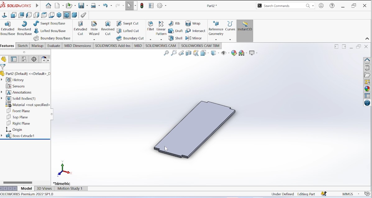
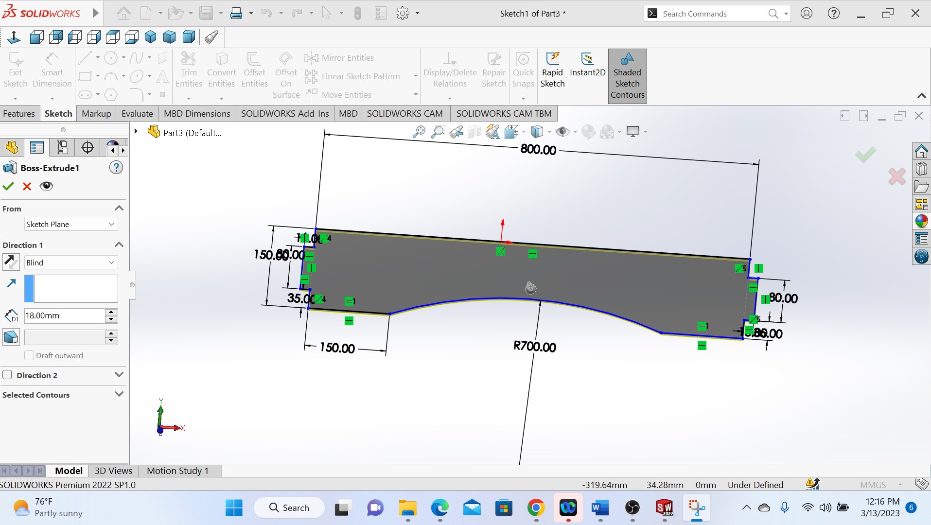
1.The first step is to open my solidworks software and select the front plane and start sketching a rectungular shaped object
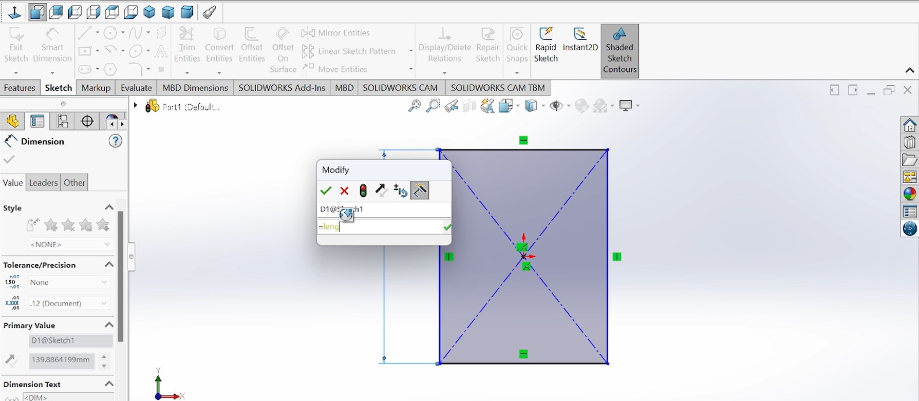
As this piece is for the sides(Left and right) that will be positioned vertically as supports, here the 2 supports are needed and this means that I designed one piece and the second will be duplicated from this during assembling stage.
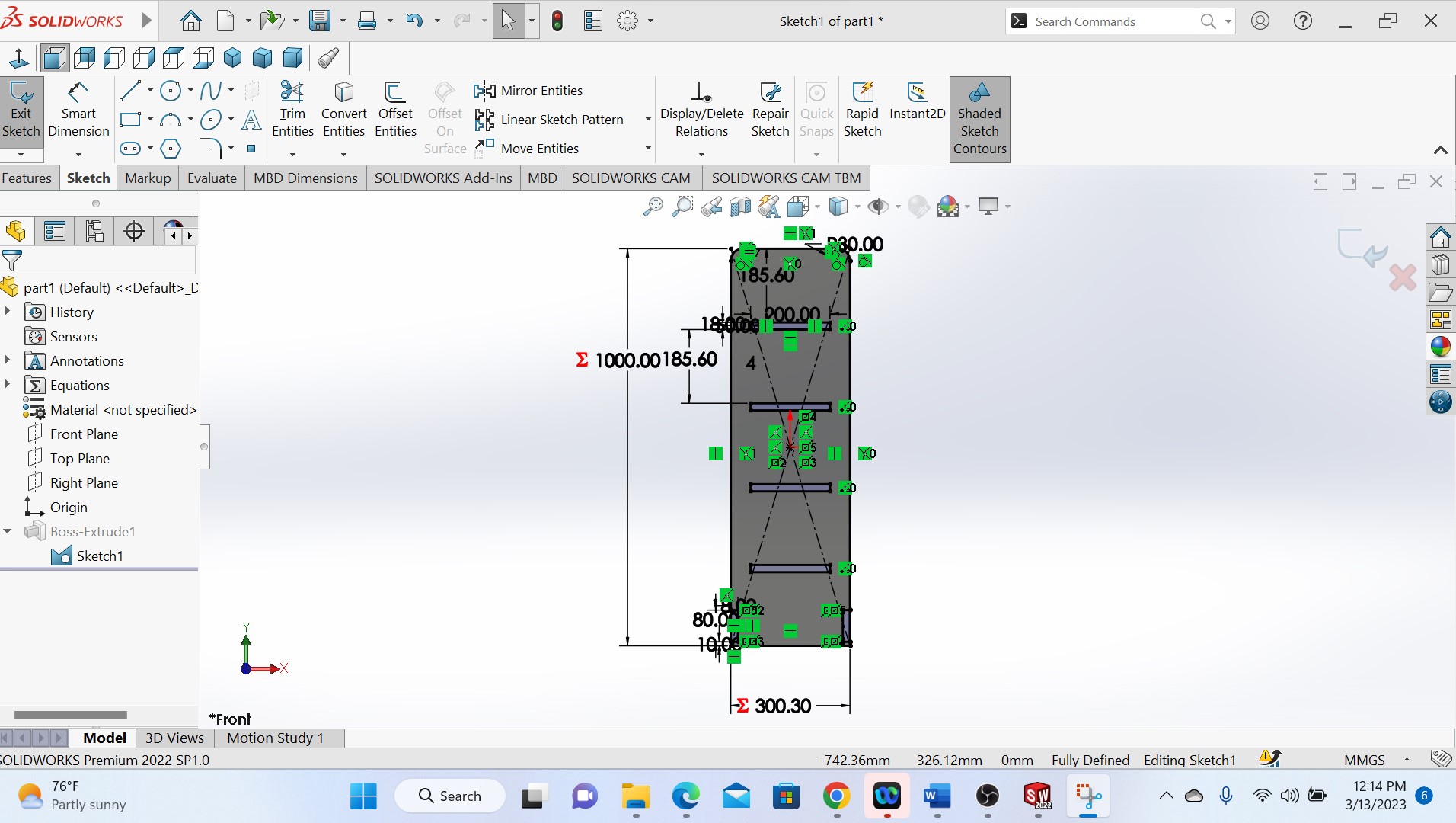
After sketching a rectangular object, I gave it the measures by using smart dimensions that is parametric.

Then after designing and giving the dimensitions and trimming the unwanted parts, the piece has been extruded then looks like this in the above photo:
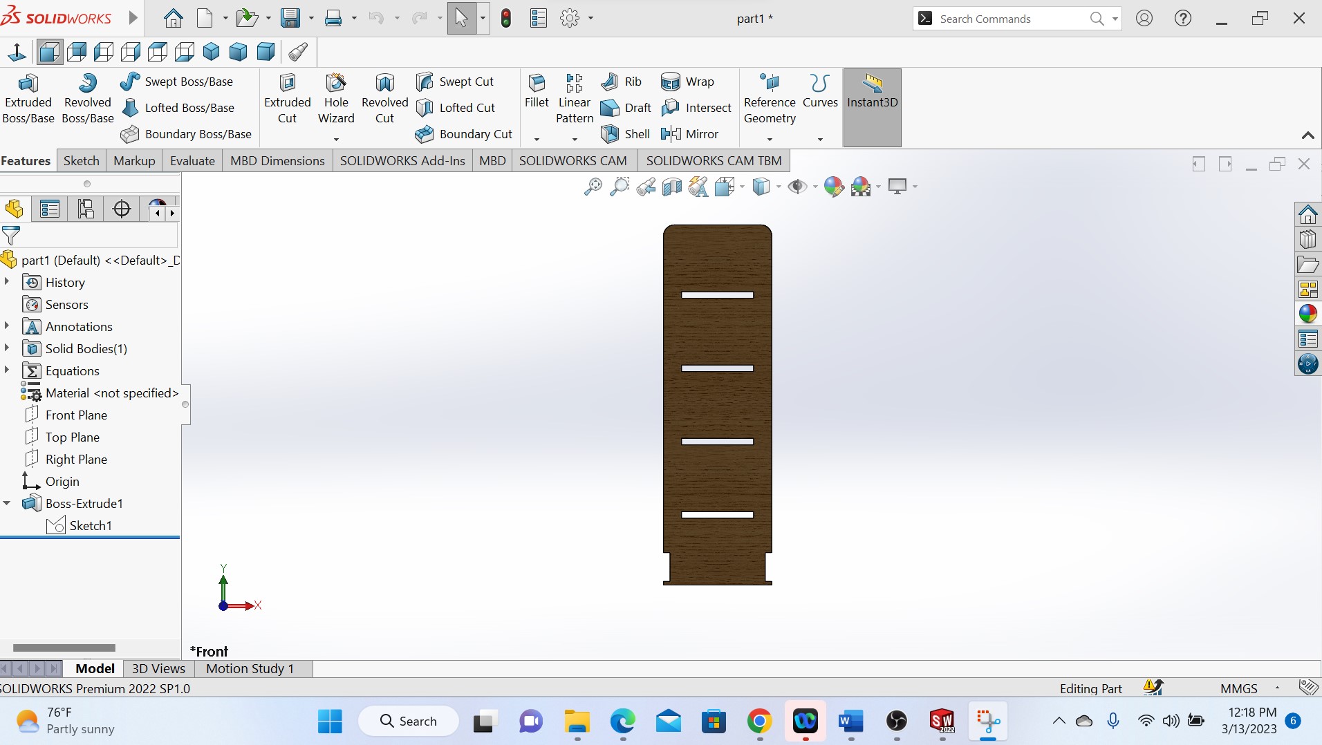
Above photo shows a final piece and colored
As my object will have the middle pieces(holders) where the shoes will be holded, after designing the side pieces, the next is to design the holders, and the procedures are the same
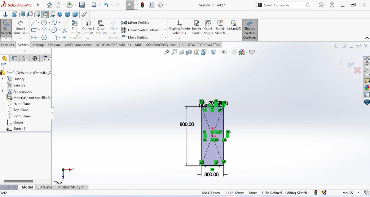
As those holders are also the rectangular shape, I designed one piece and others will be duplicated.And I chose the medium quantity of shoes to be holders which determined by the number of piece holders thare are four.
Above photo shows one holder piece after extruding.
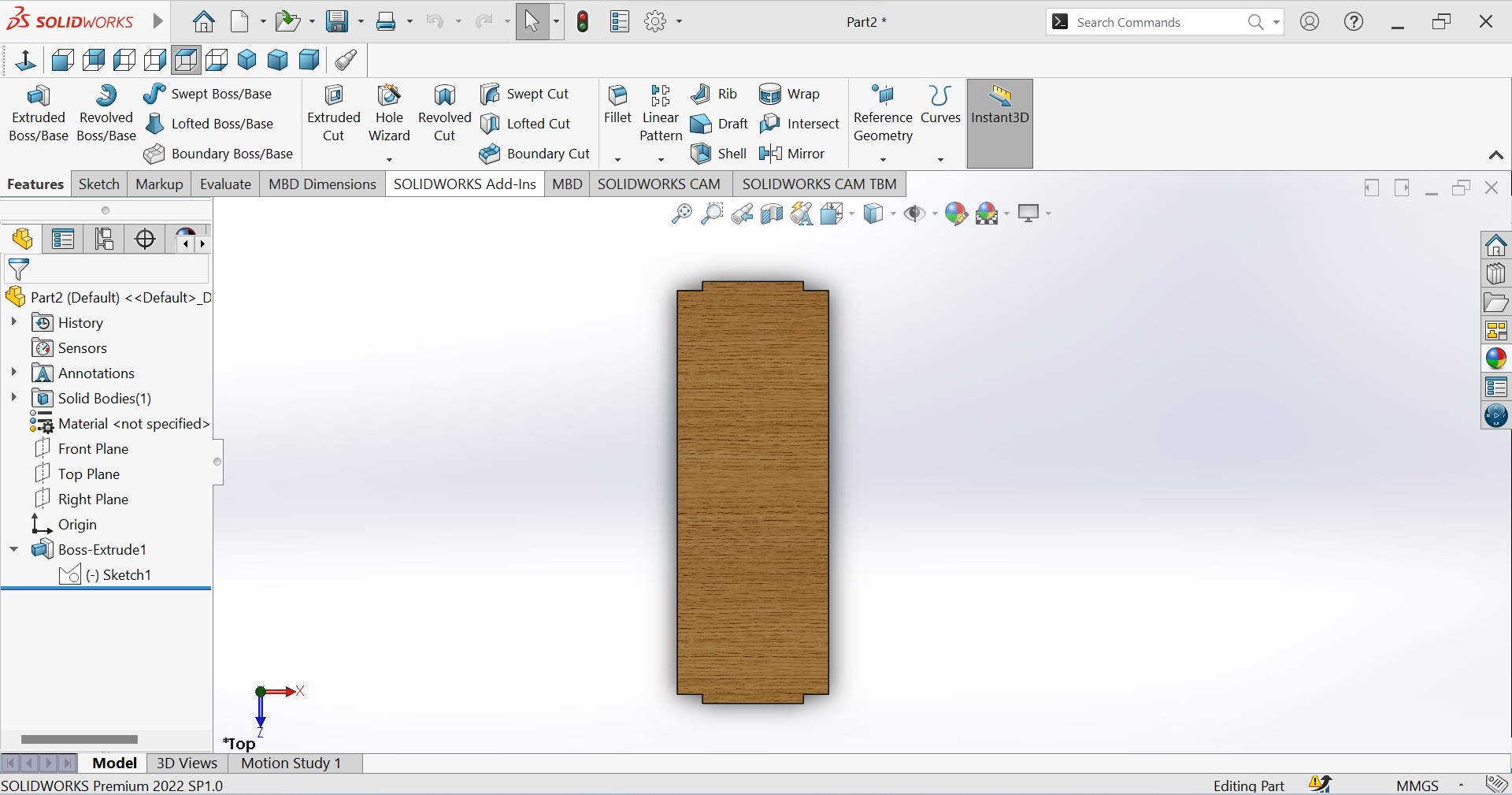
The colored holder piece to be assembled with others
As shown in the above photo, the next step is to design the down piece of the whole object where it will be supported down.
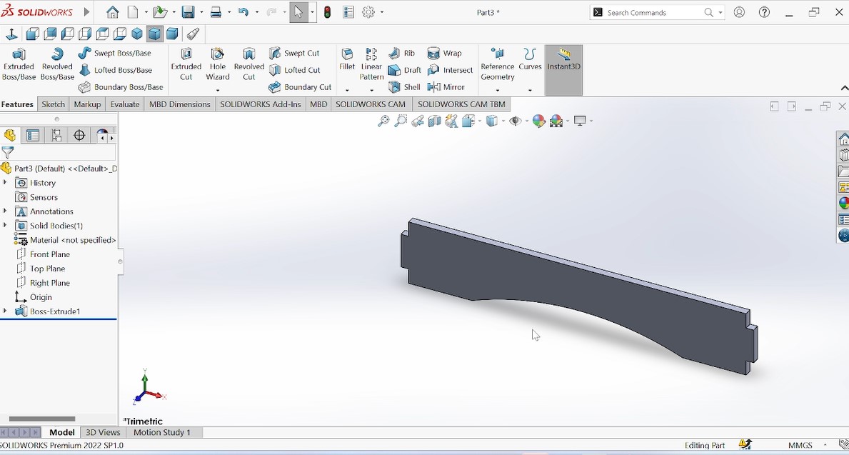
Extruded piece after extruding.
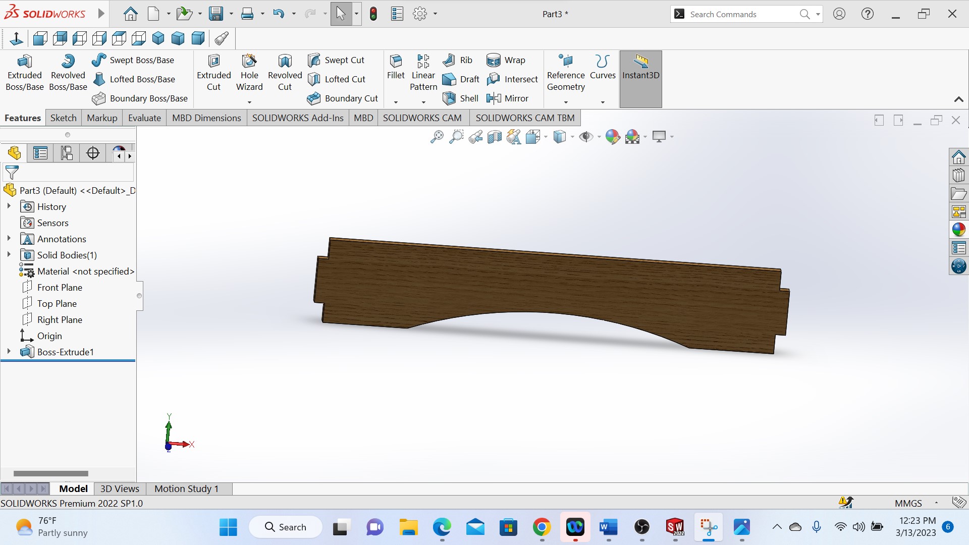
The above is a colored piece
After designing all needed pieces, the next is to assemble them in solidworks in order to make sure that after cutting also will be fitted.
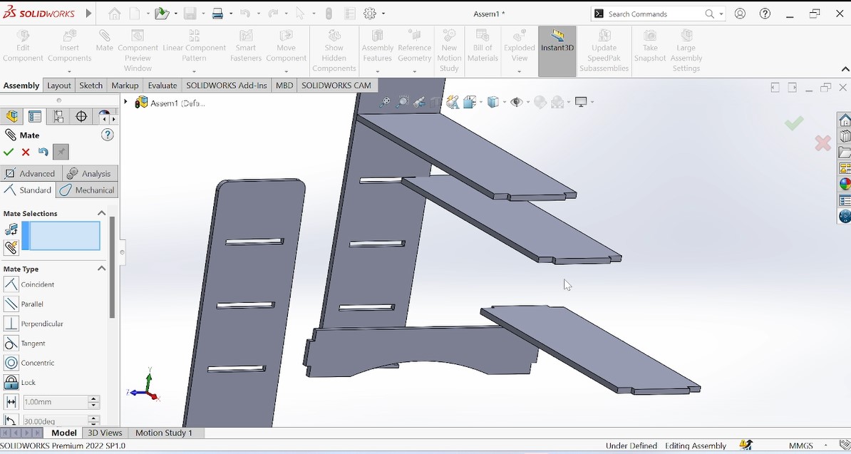
The photo above shows all pieces to be assembled

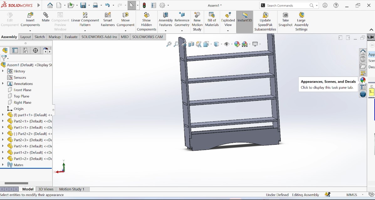
The photo above show the complete object after assembling.
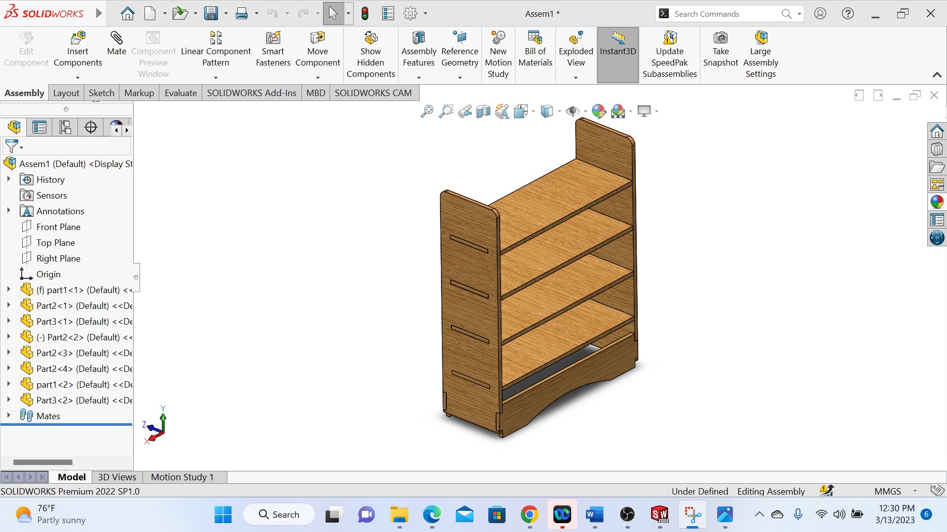
Above photo shows the final designed and colered object and the next step is to manufacture my object with CNC machine.
Making/setting the CAM-Toolpath
CAM-toolpath: CAM (Computer-Aided Manufacturing) toolpath is a sequence of operations that a CNC (Computer Numerical Control) machine uses to produce a part from a digital 3D model. A CAM toolpath is created by CAM software, which takes the 3D model and determines the most efficient way to cut the material to create the desired shape.
The CAM toolpath includes information about the cutting tool, such as its size, shape, and material, as well as the cutting parameters, such as the feed rate, spindle speed, and depth of cut. The toolpath also includes the specific path the cutting tool will take as it removes material from the workpiece, which can include roughing, finishing, drilling, and other operations.
CAM toolpaths can be customized to optimize for factors such as material removal rate, surface finish, and tool life. The goal is to create an efficient toolpath that produces a high-quality part while minimizing waste and maximizing productivity.
Steps used to set my CAM toolpaths
During the production of my designed model, I used a VCarve Pro for a Shopbot as CAM software because we have Shopbot CNC machine in our workshop. So down here there are some steps I pass through to set my CAM-toolpath:
- 1. Save each my designed models from solidworks with dxf format
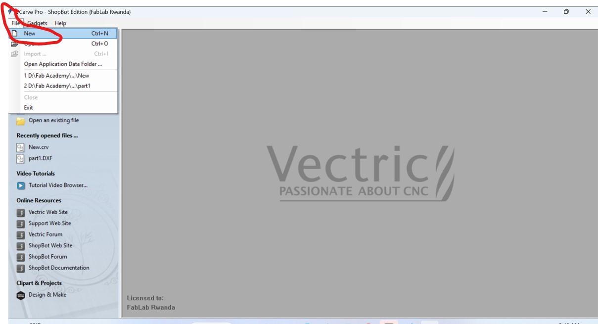
- 2. Open VCarve Pro and create a new file
- 3. Set the material size and thickness
- 4. Import my designed 3D model to machine
- 5. Configure the job settings such as the units, XY datum position, and toolpath depth
- 6. Creating vectors by tracing the shapes using Create 3D Toolpaths option.
- 7. Choose the tool that I want to use by seting the parameters such as the cutting diameter, cutting depth, and spindle speed.
- 8. Select the machining operations to use, such as profiling, pocketing, or drilling.
- 9. After choosing the tool and machining operations, I generated the toolpath by clicking the "Calculate" button. The software generated the toolpath based on the settings I have chosen.
- 10.Preview the toolpath to make sure it looks right. Check for any errors or collisions that may have occurred.
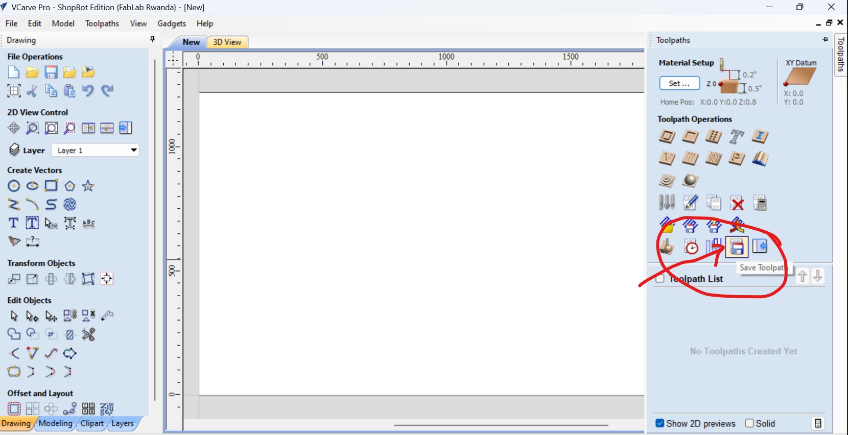
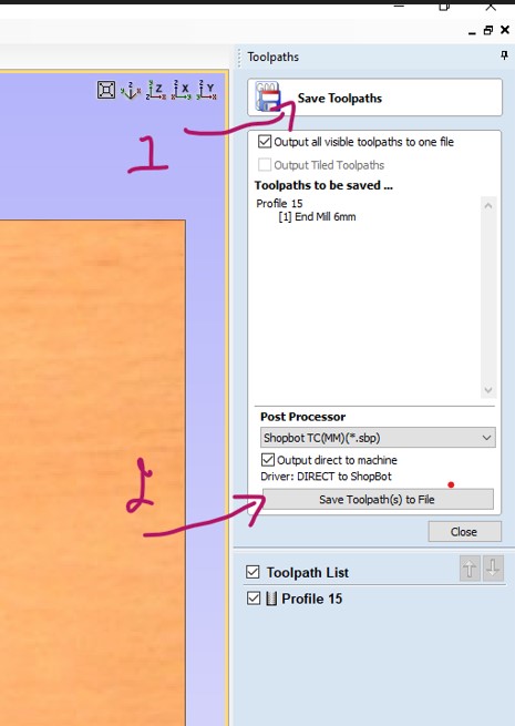
- 11.Save the toolpath by clicking the "Save Toolpath" button and Choose the file format I want to use and save the file to my computer.
- 12.Transfer the file to your Shopbot CNC machine using a USB drive
- 13.Set up the CNC machine by loading the material, attaching the tool, and setting the zero position.
- 14.Start the machine


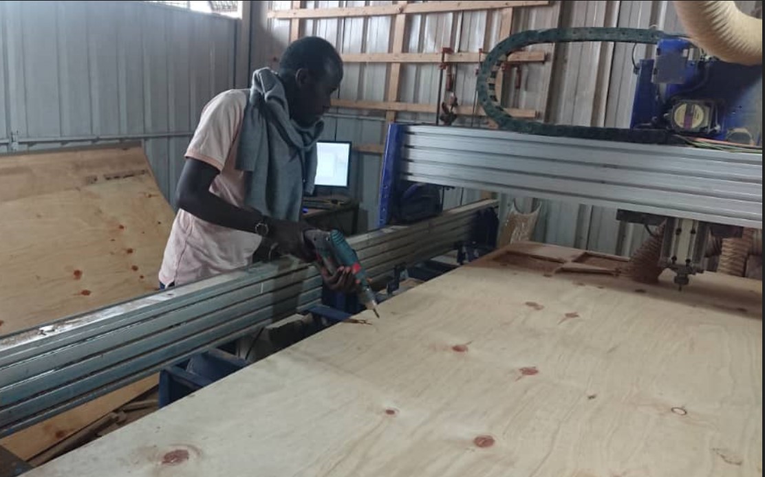
Photo above is when fixing the workpiece(MDF) on bed of CNC shopbot machine
After fixing the workpiece, I opened the vCarve Pro_ShopBot and start setting the cutting Toolpaths
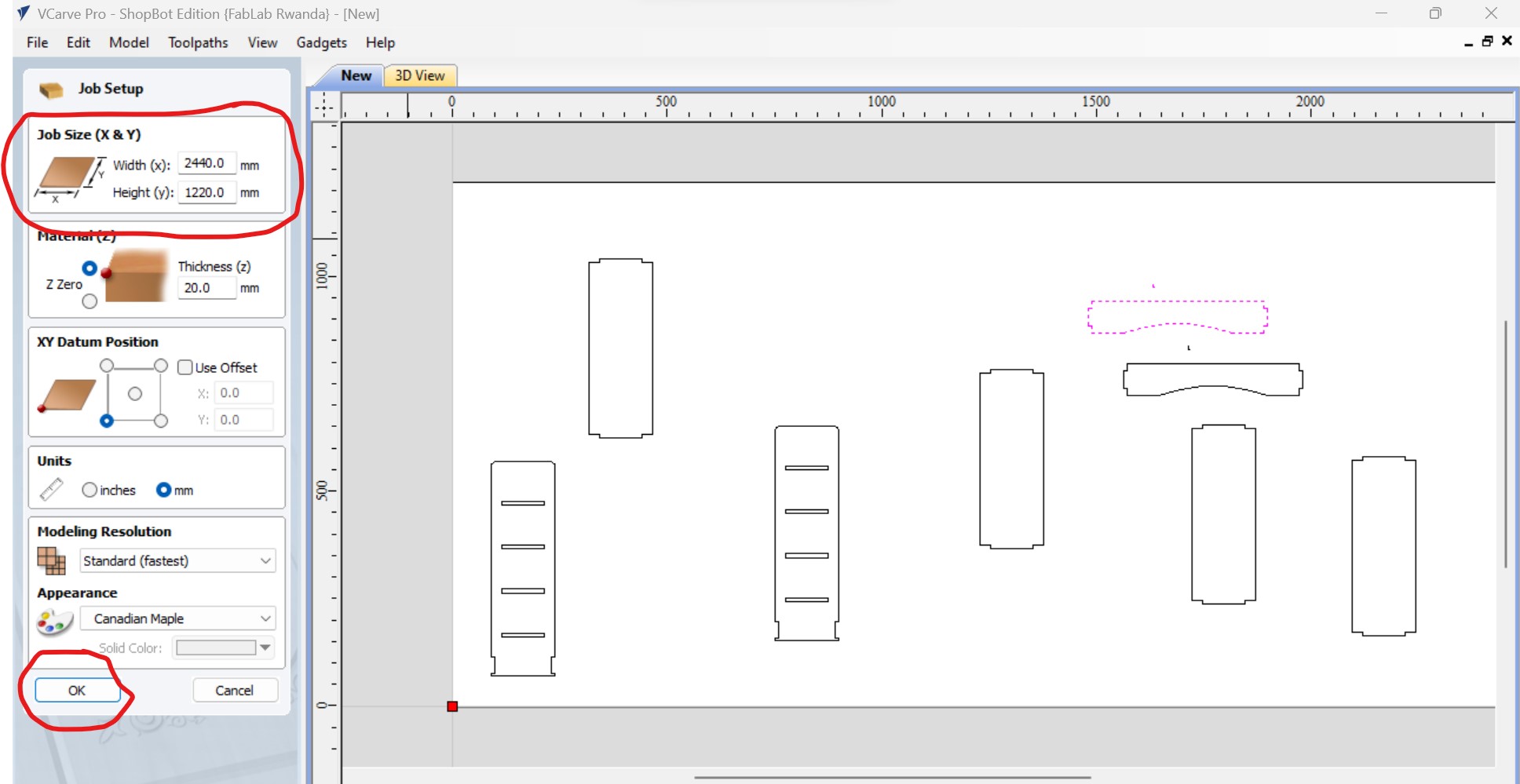
After selecting the new, the working place where you place your designs displayed and set the job size such as X&Y where X is width and I setted at 2440mm and height(Y) of 1220mm refered to the size of our CNC machine and cick ok. as shown below,
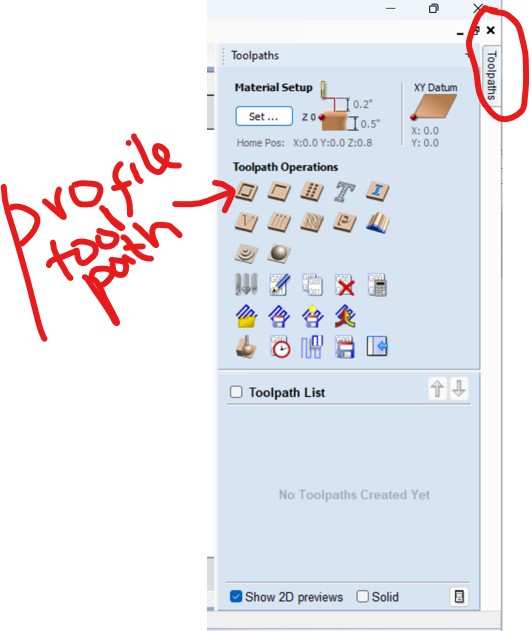
The next is to arrange the designs to be cutted into the working place and set the toolpaths and select the profile toolpath as I need to cut:
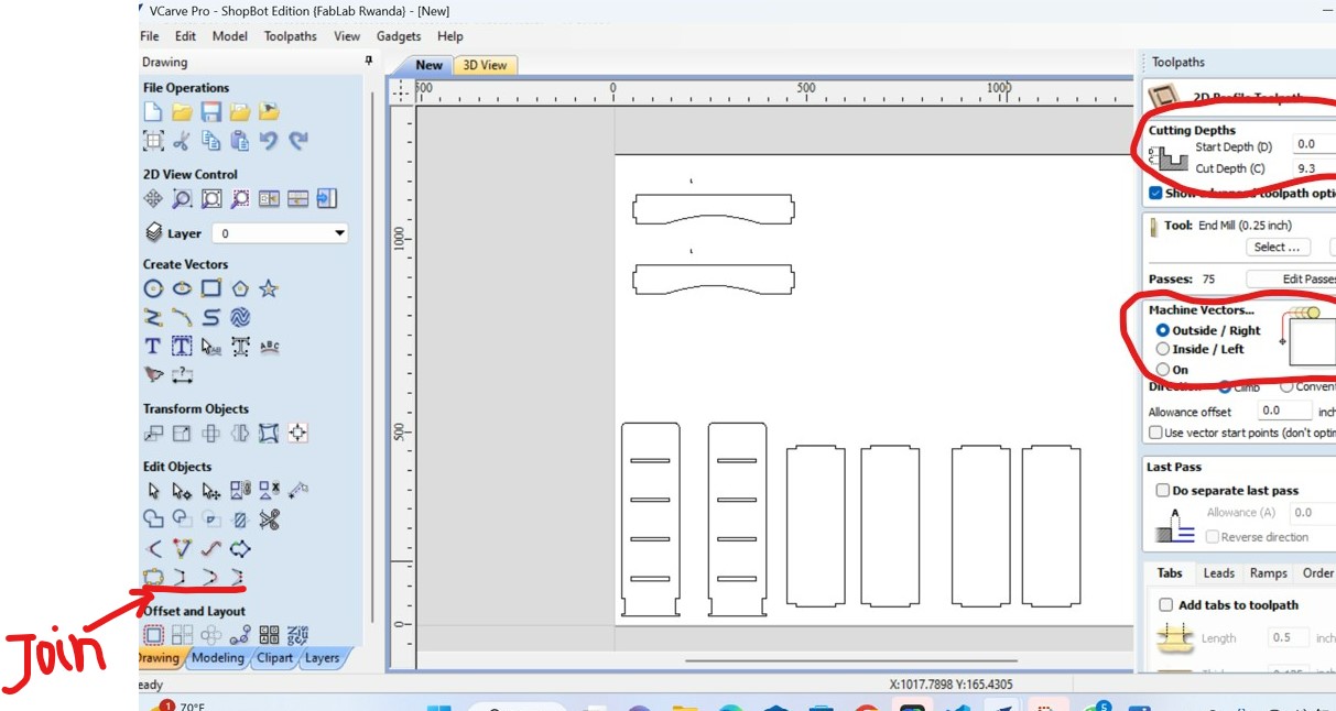
As I have many pieces, first I joined them
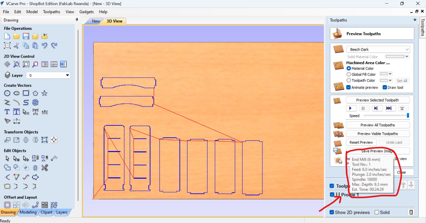
After selecting the profile toolpath, I setted the cutting depth, here I choose the cutting depth of 9.3mm as the thickness of my material is 9mm in order to take care of clearence.
On the same page, I also setted the machine vectors, and I setted it to pass or to cut outside

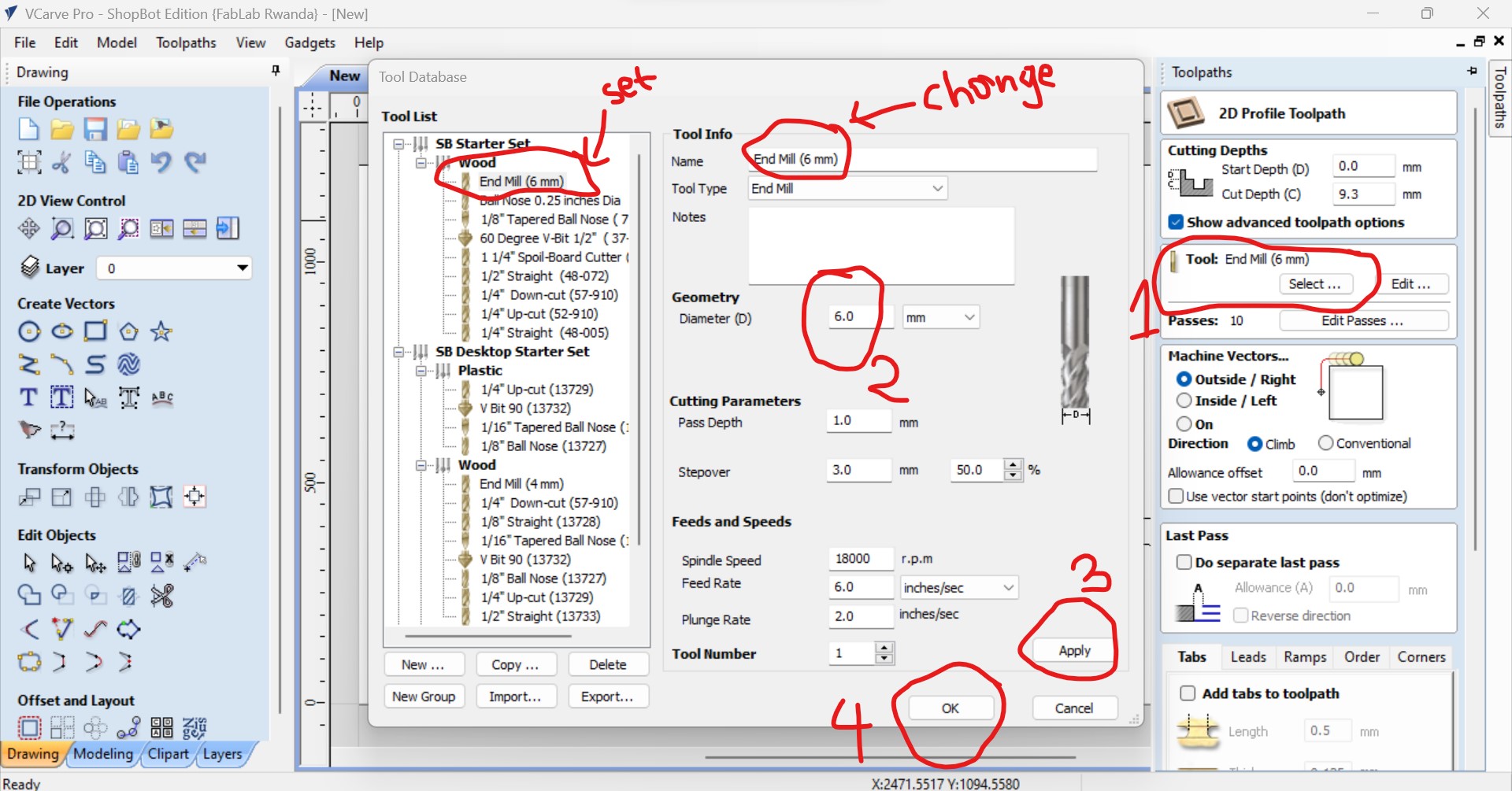
After I setted the milling tool, here i setted it on 6mm(tool diameter used) as the one I used then apply and click ok as shown in the following figure:
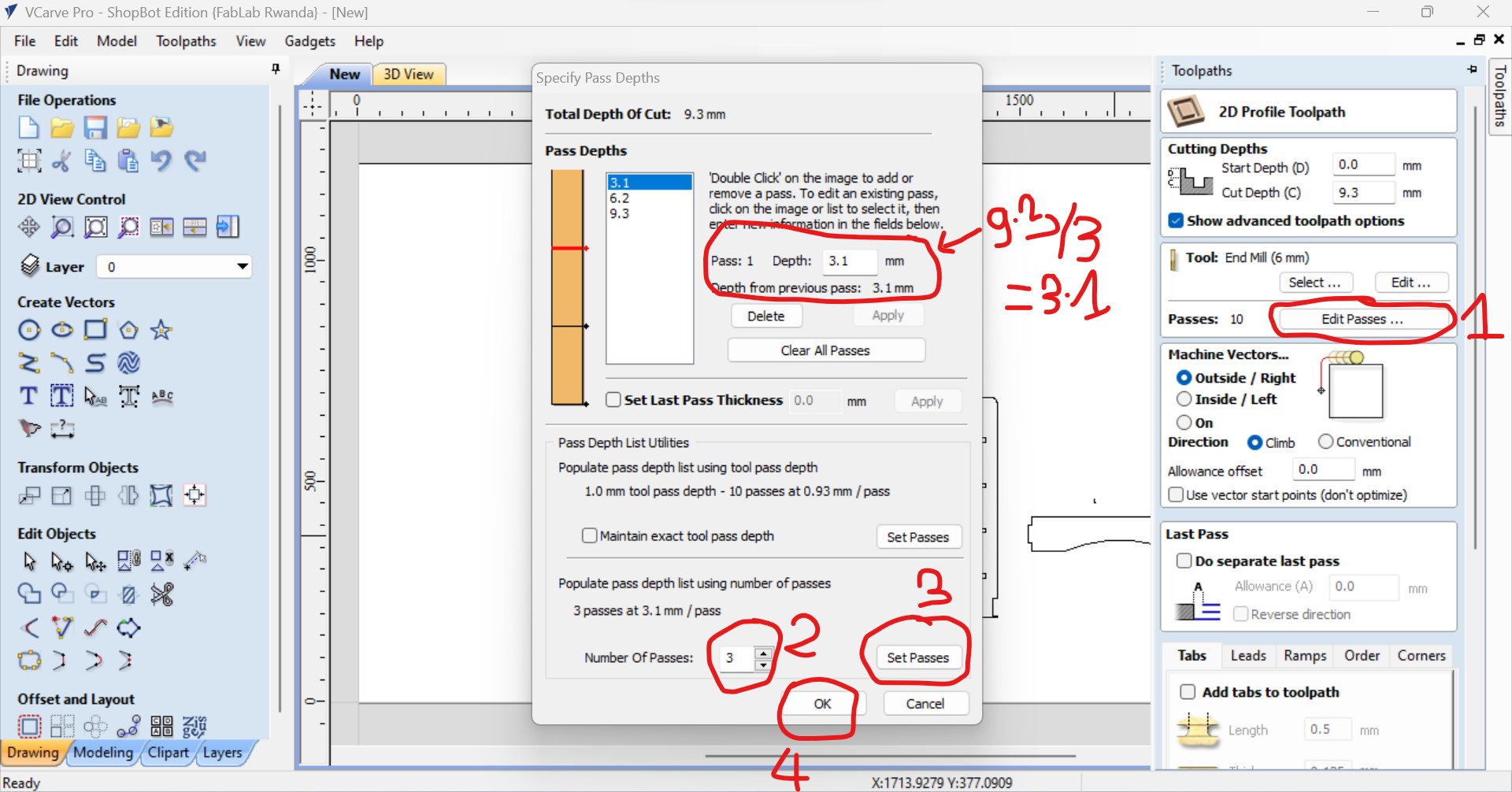
In the toolpath also, you set the number of passes as the number of turns the machine will passes when cutting.
For my work I setted 3 times and click on set passes then the depth of each turns will be culculated and displayed automatical which means that each trun it will cut 9.3/3=3.1mm as total depth is 9mm.
Afer all toolpaths setting, I clicked on calculate,
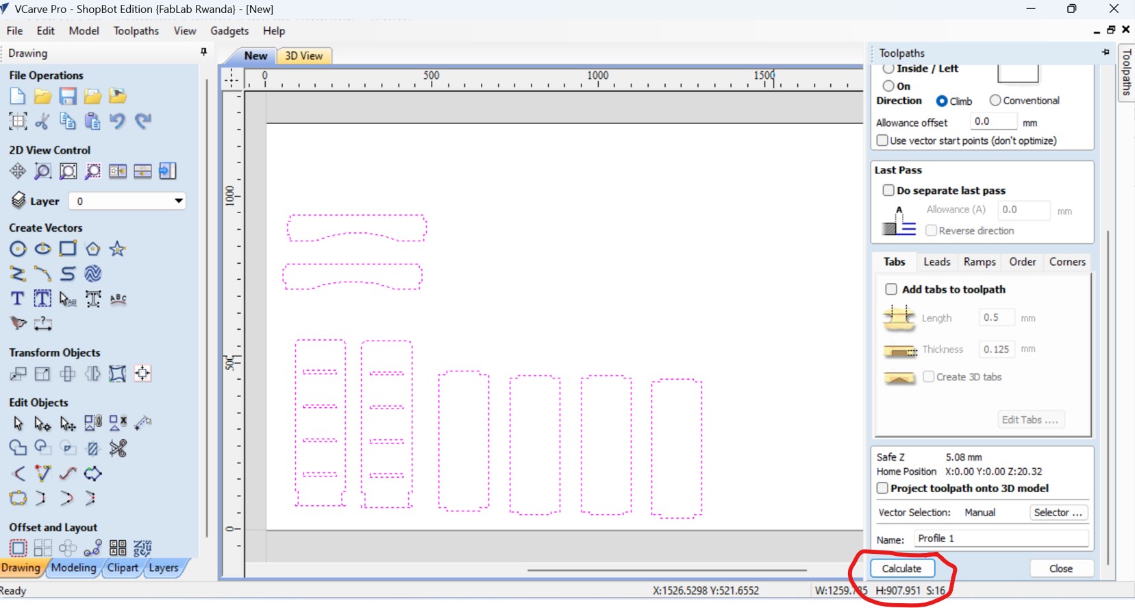
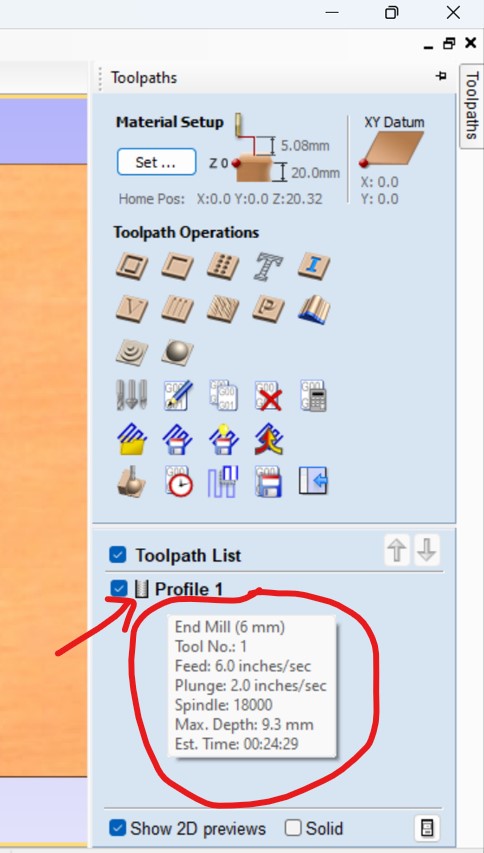
After clicking on calculation, the working wood with placed design is displaed, as I fixed the MDF wood on the bed of CNC machine, then place the cursor on profile and diffrent useful information such time it will take to finish the work is displayed.
After all, save the G code file in any folder
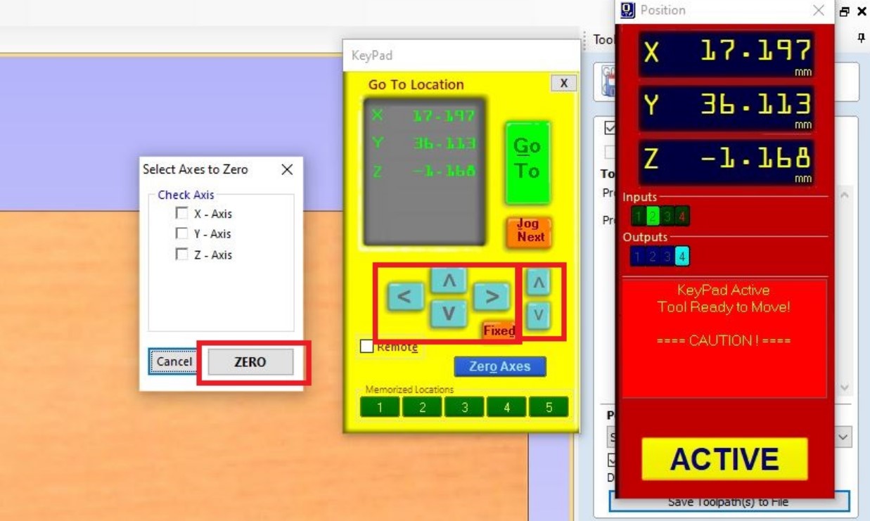
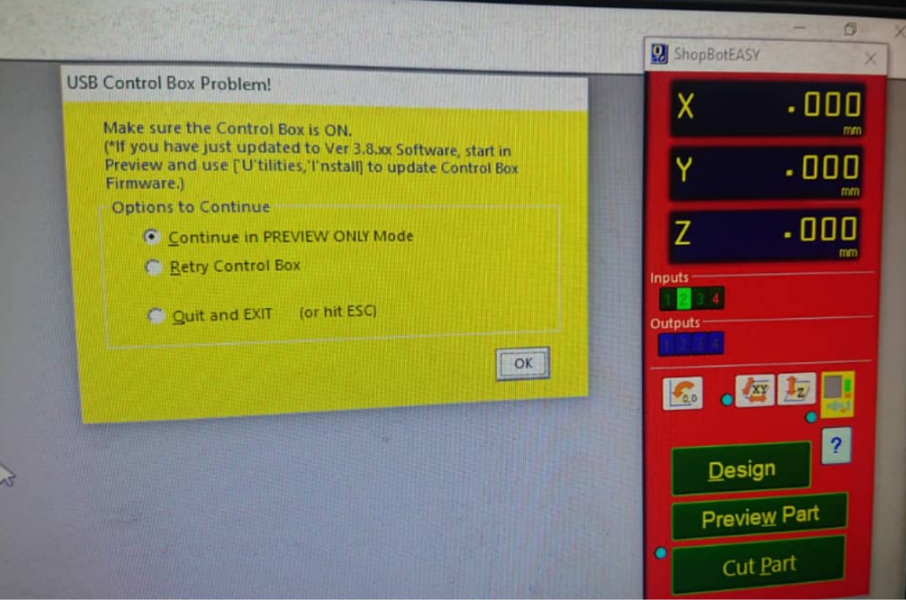
After all those settings, the next is to set XYZ axis at the orgin as 0 with/in shopbot Easy software by clicking the navigation buttons or similar to keyboard then click on zero button to set them at 0.
After setting the origin, the next is start cutting by clicking on cut part and then ok on warning yellow box or space on keyboard as shown by photo below:
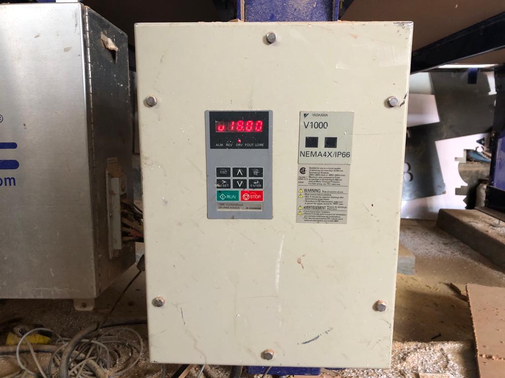
For Our CNC shopbot, the speed of 1800 RPM is set by default as shown in the following photo, and I cutted with the feeds set at 6.0inches/sec.
Below photo shows the display of different information before milling such as feed, tool used,spindle(machine) speed, plunge, etc.
Assembling the pieces for final object!!!
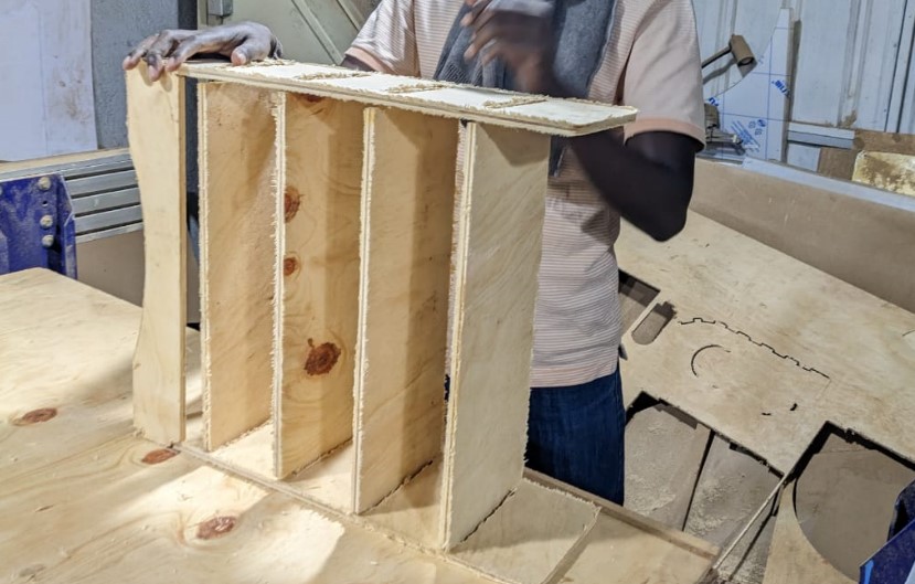
When assembling, I made sure that the parts fit well,actually what I did in order the pieces to fit I took much care and consideration on clearance, as I used MDF of 9mm of thickness, I left the hole of 9.3mm( I mean where the teeth of other pieces fit).
Problems I faced and how I fixed them
1.The first challenge I faced when working on this assignment is that I made all designs refering to the size of materials to be used and when its time for cutting I found that the available materials and my design sizes are not matching. So the quick resolution was to go and re-design mostly by adjusting the dimensions which actually caused the delay in finishing the work.
2.The second problem I faced is what happened during cutting, Normally depending on the design a CNC's tool goes straight when cutting, but ours when cutting formed some curves which was not on design and that caused the complete changes on the final product!! when I realized that I though that the head of machine is not well fixed and I dismounted it and fix it properly hoping that the issue is going to be resolved but unfortunately was wrong beacuse it peresisted!!
Still looking for solution, I changed the cutting tool and luckly the problem resolved perectly.
All those works(designs) done in Computer Controlled Machining have been saved as files and they can be accessed and downloaded as a whole zipped folder via here
The DXF files also can be downloaded from here
NAVIGATION
USEFUL LINKS FOR MORE KNOWLEDGE
https://randomnerdtutorials.com/ https://www.w3schools.com/java/java_intro.asp https://www.w3schools.com/html/default.asp https://developer.mozilla.org/en-US/docs/Web/HTML/Element/brAddress
2023 All Rights Reserved. Designed by Felix NYIRIGIRA