Week 13: Embedded Networking and Communications
Embedded Networking and Communications
Assignment activities: Group assignment: Send a message between two projects If you want to explore the group Assignment Click Here Individual assignment: Design, build, and connect wired or wireless node(s) with network or bus addresses Group assignment:II.Individual assignment:
By using a microcontroller board that you have designed in Week 9 Output_Deviceswe use ESP23 Microcontroller, ESP23 Datasheet , as ESP 32 Microcontroller has a protocal ESP-NOW What is ESP-NOW? ESP Now is a communication protocol developed by Espressif Systems, the company behind the popular ESP8266 and ESP32 microcontroller platforms. It is designed for low-power and low-latency communication between ESP8266 and ESP32 devices, making it suitable for applications such as wireless sensor networks, home automation systems, and IoT (Internet of Things) devices. The following Image shows my Board used in this assignment, and this board was designed in week 9 as I cite in above stetements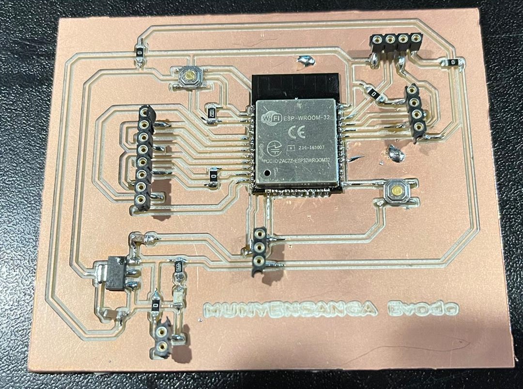 The following Image shows other used Boards (Two ESP 32 wroom)
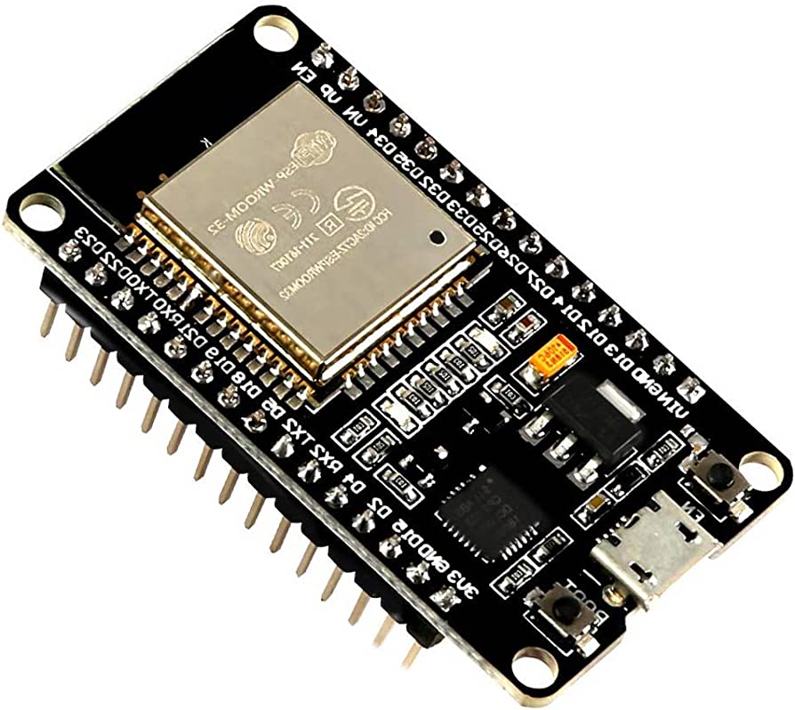 In this Assignment we used ESP Now to communicate with 3 differents boards to communicate
- 1. Sender (Master): Here is Sender (Master) Mac Address 7C:9E:BD:49:4E:28
- 2. Receiver 1 (Slave): Here is Receiver1 (Slave) Mac Address 7C:9E:BD:66:6E:00
- 3. Receiver 2 (Slave): Here is Receiver2 (Slave) Mac Address 94:E6:86:05:0D:9C
                                      #ifdef ESP32
                                      #include
                                      #else
                                      #include
                                      #endif

                                      void setup(){
                                      Serial.begin(115200);
                                      Serial.println();

                                      Serial.println(WiFi.macAddress());
                                      }

                                       void loop(){

                                       }
The MAC Address for Slaves Boards
uint8_t receiverAddress1[] = {0x94, 0xE6, 0x86, 0x05, 0x0D, 0x9C};
uint8_t receiverAddress2[] = {0x7C, 0x9E, 0xBD, 0x66, 0x6E, 0x00};
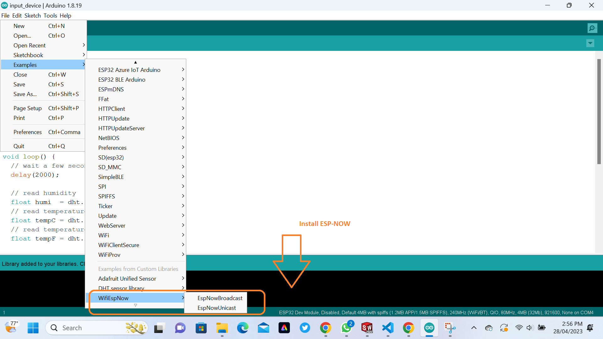
The following Image shows when we Intall ESP-NOW
 Here are code we used for Sending (Master :Mac Address 7C:9E:BD:49:4E:28)
                                        #include
                                            #include

                                            // REPLACE WITH YOUR ESP RECEIVER'S MAC ADDRESS
                                            uint8_t Receiver_Address1[] = {0x94, 0xE6, 0x86, 0x05, 0x0D, 0x9C};
                                            uint8_t Receiver_Address2[] = {0x7C, 0x9E, 0xBD, 0x66, 0x6E, 0x00};
                                            uint8_t Receiver_Address3[] = {0x84, 0xCC, 0xA8, 0x5E, 0x52, 0x44};

                                            typedef struct struct_message {
                                              int integer;
                                              char character[100];
                                            } struct_message;

                                            struct_message message;

                                            void data_sent(const uint8_t *mac_addr, esp_now_send_status_t status) {
                                              char address[18];
                                              Serial.print("Sent to: ");
                                              snprintf(address, sizeof(address), "%02x:%02x:%02x:%02x:%02x:%02x",
                                                       mac_addr[0], mac_addr[1], mac_addr[2], mac_addr[3], mac_addr[4], mac_addr[5]);
                                              Serial.print(address);
                                              Serial.print(" status:\t");
                                              Serial.println(status == ESP_NOW_SEND_SUCCESS ? "Delivery Success" : "Delivery Fail");
                                            }

                                            void setup() {
                                              Serial.begin(115200);

                                              WiFi.mode(WIFI_STA);

                                              if (esp_now_init() != ESP_OK) {
                                                Serial.println("Error initializing ESP-NOW");
                                                return;
                                              }

                                              esp_now_register_send_cb(data_sent);

                                              esp_now_peer_info_t peerInfo;
                                              peerInfo.channel = 0;
                                              peerInfo.encrypt = false;

                                              memcpy(peerInfo.peer_addr, Receiver_Address1, 6);
                                              if (esp_now_add_peer(&peerInfo) != ESP_OK){
                                                Serial.println("Failed to add peer 1");
                                                return;
                                              }

                                              memcpy(peerInfo.peer_addr, Receiver_Address2, 6);
                                              if (esp_now_add_peer(&peerInfo) != ESP_OK){
                                                Serial.println("Failed to add peer 2");
                                                return;
                                              }

                                              memcpy(peerInfo.peer_addr, Receiver_Address3, 6);
                                              if (esp_now_add_peer(&peerInfo) != ESP_OK){
                                                Serial.println("Failed to add peer 3");
                                                return;
                                              }
                                            }

                                            void loop() {
                                              message.integer = random(0,50);
                                             strcpy(message.character, " Message from Sender ESP32 WITH ESP-NOW BRAODCAST (EVODE)!!");

                                              esp_err_t outcome = esp_now_send(0, (uint8_t *) &message, sizeof(struct_message));

                                              if (outcome == ESP_OK) {
                                                Serial.println("Sent with success");
                                              }
                                              else {
                                                Serial.println("Error sending the data");
                                              }
                                              delay(2000);
                                            }
Here are code we used for Receiving (Slave Mac Address 7C:9E:BD:66:6E:00 and 94:E6:86:05:0D:9C )
                                        #include
                                            #include

                                            //Must match the sender structure
                                            typedef struct struct_message {
                                              int integer;
                                              char character[100];
                                            } struct_message;

                                            struct_message message;


                                            void data_receive(const uint8_t * mac, const uint8_t *incomingData, int len) {
                                              memcpy(&message, incomingData, sizeof(message));
                                              Serial.print("Data Received FROM ESP32 SENDER: ");
                                              Serial.println(len);
                                              Serial.print("Integer: ");
                                              Serial.println(message.integer);
                                              Serial.print("INCOMING MESSAGE : ");
                                              Serial.println(message.character);
                                              Serial.println();
                                            }

                                            void setup() {

                                              Serial.begin(115200);
                                              WiFi.mode(WIFI_STA);

                                              if (esp_now_init() != ESP_OK) {
                                                Serial.println("Error initializing ESP-NOW");
                                                return;
                                              }

                                              esp_now_register_recv_cb(data_receive);
                                            }

                                            void loop() {

                                            }
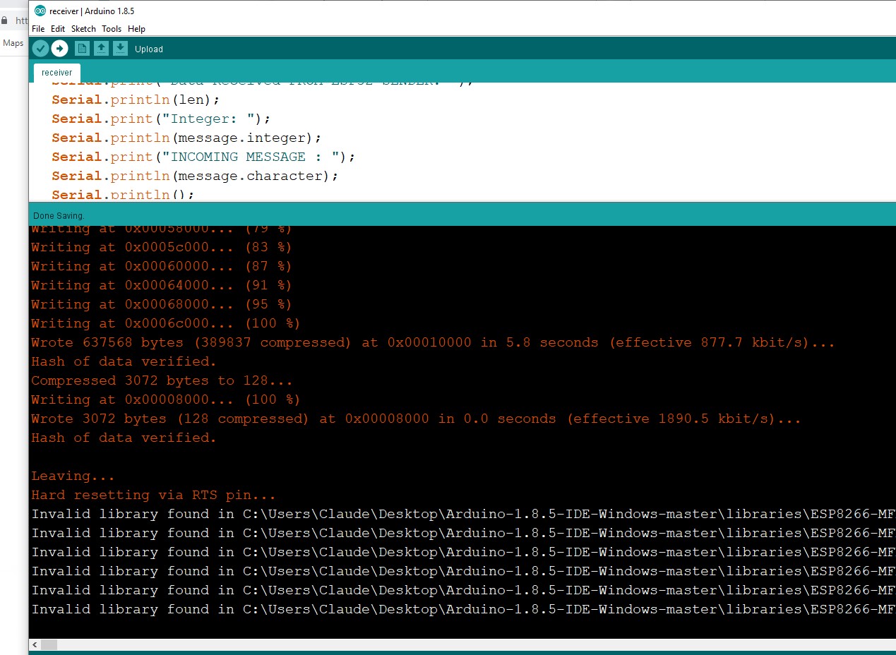
The following Image shows when we Upload the above codes in Microcontroller Boards
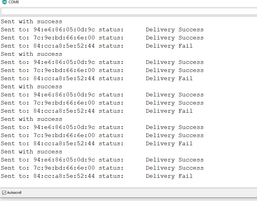
 The following Image shows The Sender (Master) used to send to other Board
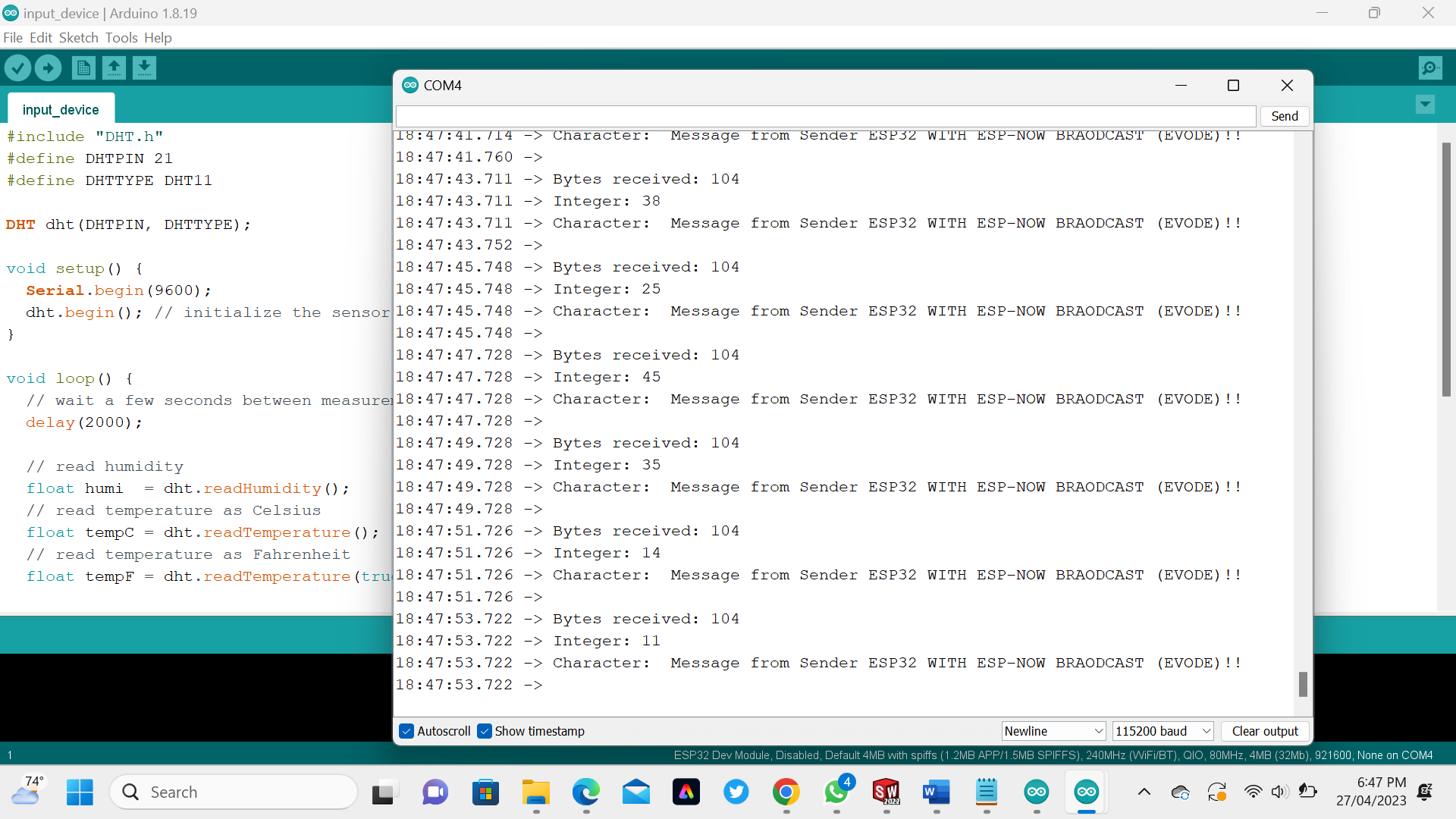
 The following Image shows The Receiver 1 (Slave) used to receive a data from The Master Board
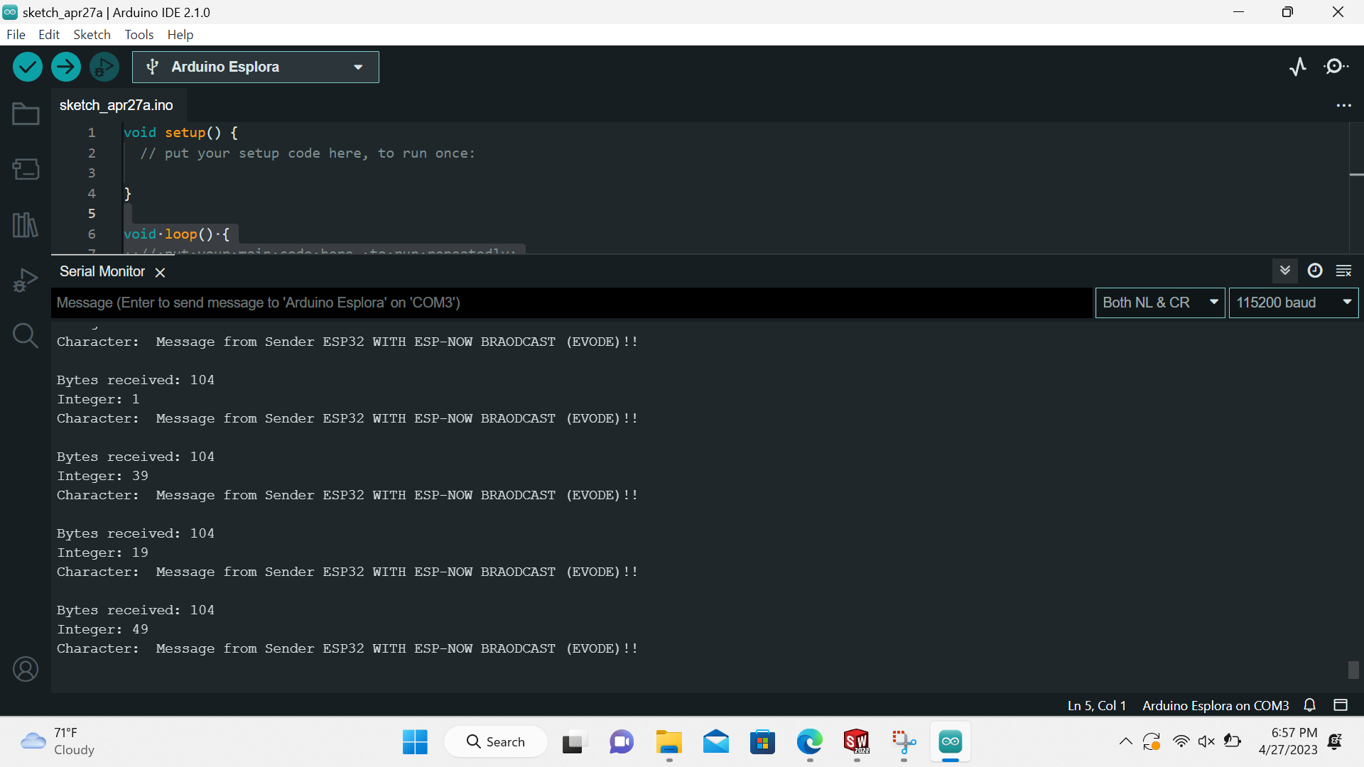
 The following Image shows The Receiver 2 (Slave) used to receive a data from The Master Board
 For found my final results of how the differents boards communicate watch the following Video
If you want to learn about my code, kindly click here