Week 9: Output Devices
Group assignment
Measure the power consumption of an output deviceIndividual assignment
-
Adding an output device to a microcontroller board I have designed and program it to do something
The task for this week was to link the output apparatus to the microcontroller circuit board that was previously designed during Week 7. In my case, I utilized the attinty45 in the electronics design week, and the resulting PCB was built around the attinty45 MCU. However, for this week's task, I opted for a different controller and switched to the esp-WROM-32 Soc chip instead. This chip boasts several advantages over the attinty45 and is the chip I intend to use in my final project.
What is the output device of microcontroller?
This section provides an overview of output devices commonly used with microcontrollers, which can be classified into two main types: mechanical and electronic. Mechanical output devices generate motion, while electronic output devices produce light or sound.
DC motors are among the simplest types of mechanical output devices used with microcontrollers. They convert electrical energy into rotational motion and have two terminals. By reversing the polarity of the voltage applied to the motor, its direction of rotation can be controlled.
Common examples of mechanical output devices include motors and actuators, with DC motors, stepper motors, and servo motors being particularly popular for microcontroller applications. In contrast, electronic output devices include LEDs and buzzers.
LEDs are commonly used output devices to provide status information or feedback to the user in microcontroller systems. They are low-cost and have low power consumption. They can be directly connected to a microcontroller's output pin or through a driver circuit to prevent damage due to excessive current. LEDs can be programmed to display various patterns or blink in different colors to convey specific messages to the user.
In contrast, LCD screens are utilized to display alphanumeric characters, graphics, and other data in microcontroller applications. They can show real-time system status, sensor readings, or user inputs. LCDs require more complex driver circuits than LEDs and consume more power, but they offer a high degree of customization and can display more complex information.
Creating the Circuit board
With the use of KiCad, I am going to generate a PCB layout by arranging the components onto the board and establishing the connections between them through routing the traces, all based on the schematic diagram.I followed a set of steps that resembled those I took during the Week6 Activity of electronic design and if you are interested, you can read about them.

In order to obtain a component's footprint that aligns with the ones you have already used, click on the footprint icon and explore the component libraries and their filters.

Below here is the resulting PCB layout that entails positioning the various components on the board and establishing the pathways or traces that interconnect them.

|
This is the 3D view 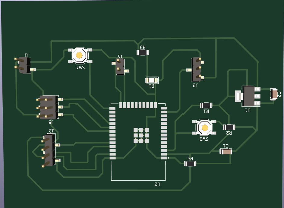
|
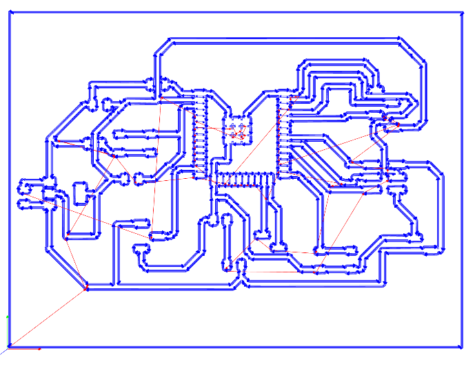
Thus, I opened the Roland SRM-20 software and click on the "File" menu. Select "Open" and choose the G-code file you just saved.
And after the tool position is set, the board cutting process begins.

|

|
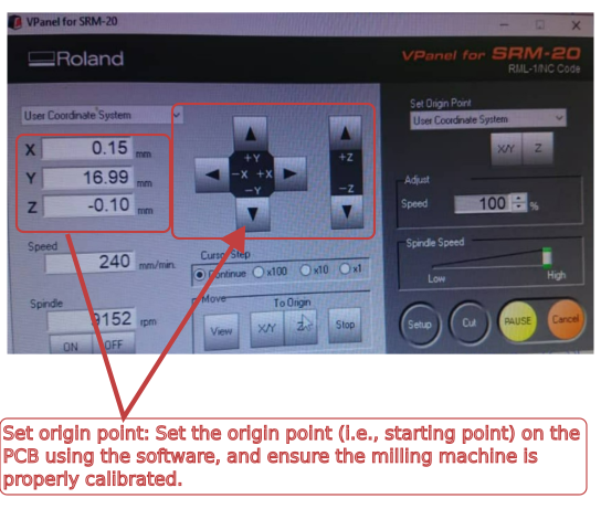
|
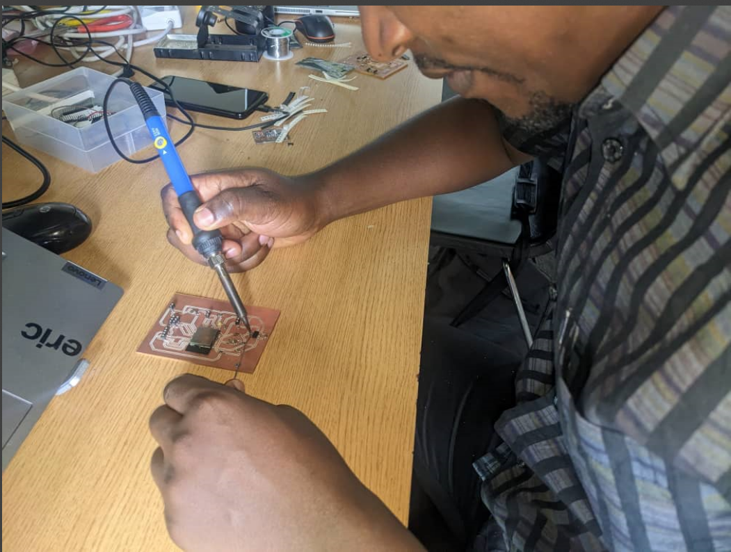
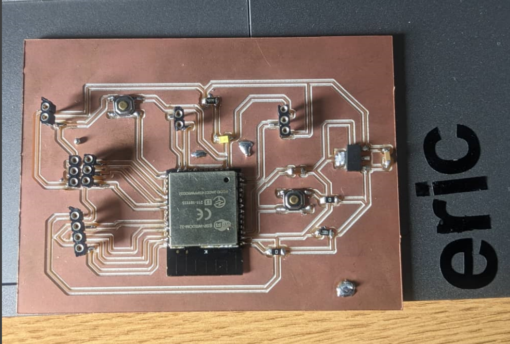
Below here is the generated PCB. And me almost done with soldering its components
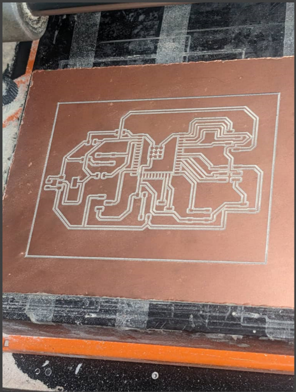
|
|
|
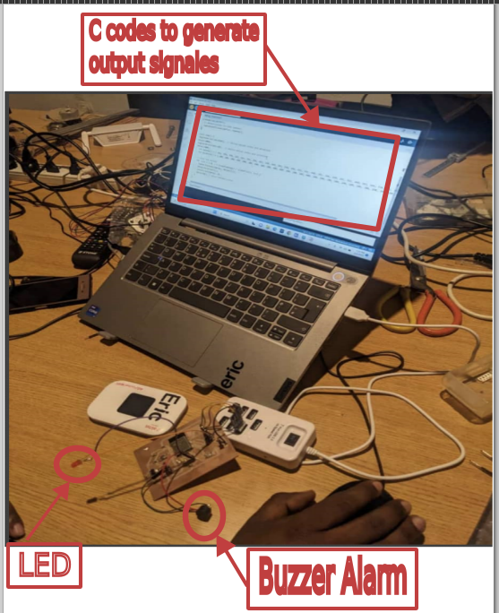
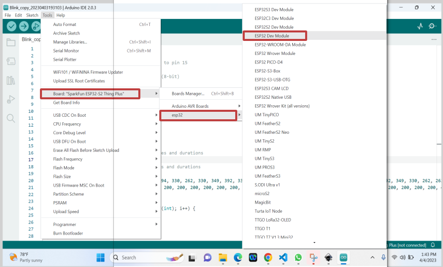
Adding and programming 2 output devices: a LED and a buzzer alarm
|
|
Below here is the used code:
      #include

const int buzzerPin = 15; // buzzer connected to pin 15
const int channel = 0; // LEDC channel 0
const int resolution = 8; // LEDC resolution (8-bit)
int led =2;
void setup() {
  // configure LEDC timer
  ledcSetup(channel, 5000, resolution);
pinMode(led,OUTPUT);
  // attach buzzer to LEDC channel
  ledcAttachPin(buzzerPin, channel);
}

void loop() {
digitalWrite(led,HIGH);  // define melody notes and durations
delay(1000);
digitalWrite(led,LOW);  // define melody notes and durations
delay(1000);
  int melody[] = { 262, 294, 330, 262, 262, 294, 330, 262, 330, 349, 392, 330, 349, 392, 392, 440, 392, 349, 330, 262, 392, 440, 392, 349, 330, 262, 262, 196, 262, 262, 196, 262 };
  int duration[] = { 200, 200, 200, 200, 200, 200, 200, 200, 200, 200, 200, 200, 200, 200, 400, 200, 200, 200, 200, 200, 200, 200, 200, 200, 200, 200, 400, 200, 200, 200, 200, 200 };

  // play the melody
  for (int i = 0; i < sizeof(melody) / sizeof(int); i++) {
    ledcWriteTone(channel, melody[i]);
    delay(duration[i]);
    ledcWrite(channel, 0);
    delay(50); // pause between notes
  }
}
The above code uses the LEDC (LED Control) library to generate tones on a buzzer connected to pin 15 of the Arduino board. The LEDC library is used to control the frequency and duty cycle of PWM (Pulse-Width Modulation) signals, which are used to generate different tones on the buzzer.The LED connected to pin 2 is used as an indicator in the code. The digitalWrite() function is used to turn the LED on and off at the beginning and end of the loop() function. This is done so that you can see when the code is running and when it is not.
Explaination of how the 2 output devices (Buzzer Alarm & LED Lighting Alert) do work:
Buzzer AlarmThe LEDC library is included using the #includeThe constants buzzerPin, channel, and resolution are defined. buzzerPin is set to 15, which is the pin number the buzzer is connected to. channel is set to 0, which is the LEDC channel used for the buzzer. resolution is set to 8, which is the LEDC resolution used to control the PWM signal. In the setup() function, the LEDC timer is configured using the ledcSetup() function. The ledcAttachPin() function is used to attach the buzzer to the LEDC channel. Two arrays are defined: melody and duration. The melody array contains the frequencies of the notes to be played on the buzzer, and the duration array contains the durations of each note. A for loop is used to iterate through the melody and duration arrays. The ledcWriteTone() function is used to set the frequency of the buzzer to the current note in the melody array. The delay() function is used to wait for the duration of the note. The ledcWrite() function is used to turn off the buzzer. Finally, a short delay of 50ms is added before playing the next note. |
LED Lighting AlertThe led variable is defined as 2, which is the pin number of an LED that will be used as an indicator in the code.In the loop() function, the digitalWrite() function is used to turn on and off the LED connected to pin 2. The digitalWrite() function is used to turn the LED on and off at the beginning and end of the loop() function. This is done so that you can see when the code is running and when it is not. When the code starts running, the LED will turn on for one second, and then turn off for one second. This is done using the digitalWrite() function and the delay() function. After this initial delay, the melody played on the buzzer starts. Once the melody is finished playing, the LED will turn on again for one second, and then turn off for one second. This is done using the same digitalWrite() and delay() functions as before. The loop() function will then start again from the beginning, playing the melody once more. This process will repeat indefinitely until the code is stopped. |
The following is the video showing how the ESP32 is interacting with 2 output devices (buzzer alarm & LED Alert):
- Used file can be found here
© 2023 | Eric NDAYISHIMIYE | All Rights Reserved