WELCOME TO MY FINAL PROJECT PAGE
When considering ideas for my final project, I had a couple of options in mind. The first idea that came to me was to design a smart container for fresh fish to help local fishermen preserve their catch for longer periods and reduce food waste. However, as I continued to brainstorm, I also came up with another idea of the Digital Suggestion Box (DsBOX) for Service Quality Assessment.
After careful consideration, I ultimately decided to pursue the DsBOX project, as I believe it has the potential to make a significant impact in my country by providing valuable data on citizen satisfaction and driving improvements in service delivery.
Below here is the sketch:
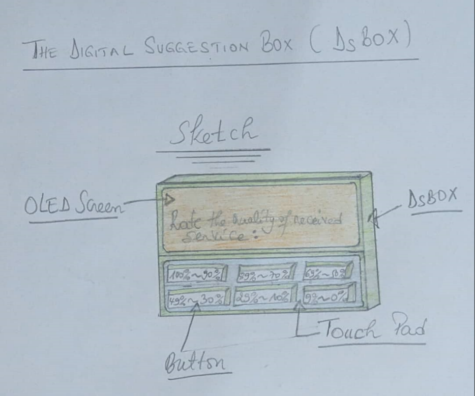
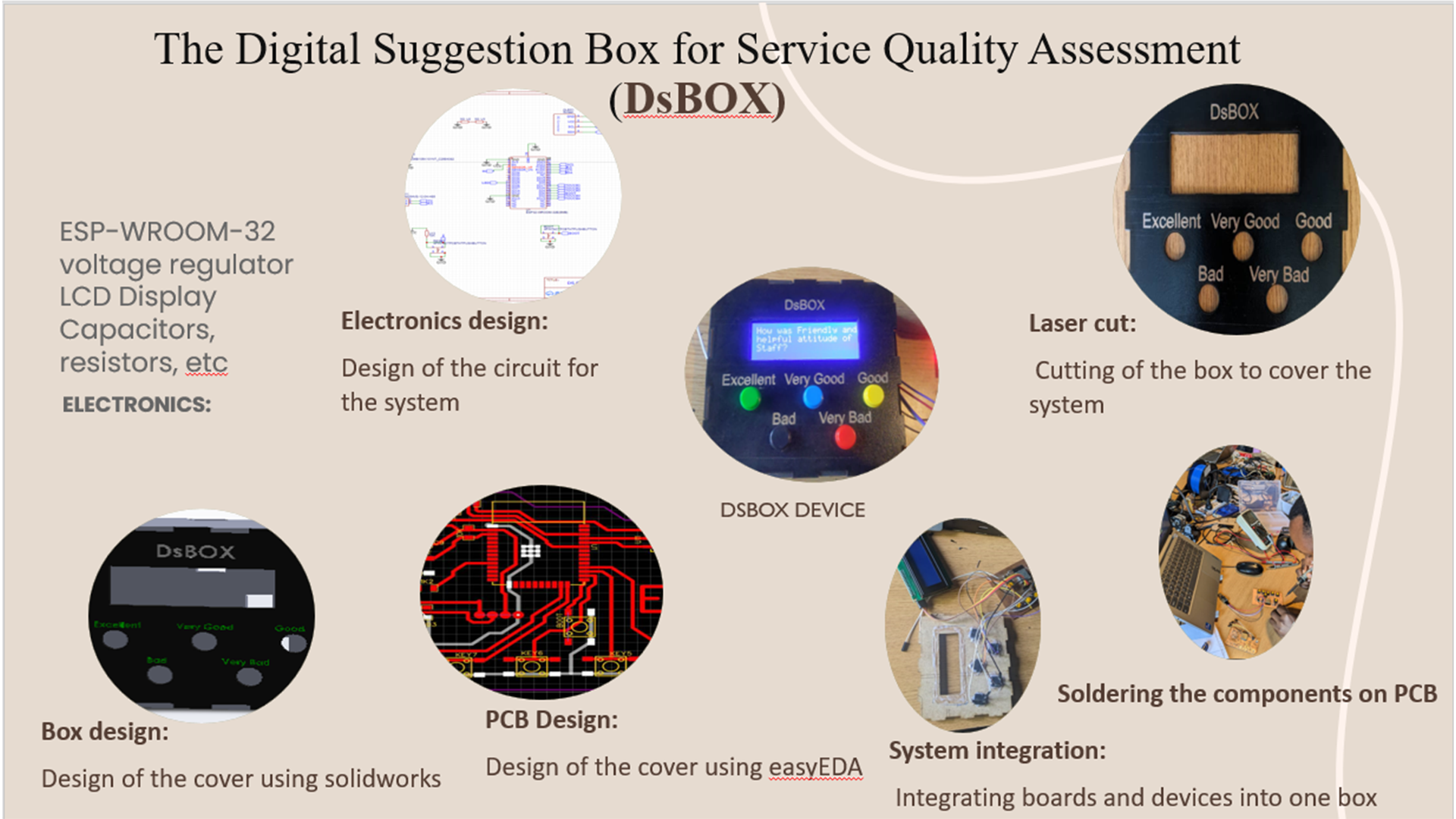
The Digital Suggestion Box for Service Quality Assessment (DsBOX)
Introduction:
- The Digital Suggestion Box for Service Quality Assessment (DsBOX) is a tool made to get customer feedback on how well a particular office served them. The gadget permits clients to rate the nature of administration they got by squeezing a button that compares to their degree of fulfillment. After that, the feedback is saved in the memory of the device and sent to a server, where management can use graphs to analyze the data and make decisions based on the feedback.
Objective:
- The creation of DsBOX that can collect and analyze customer feedback on service quality is the primary objective of this project. The task plans to assist workplaces with working on their administrations and upgrade customer loyalty by recognizing regions and/or areas that need improvement in view of criticism from clients (customers).
Features:
-
The following features are included in DsBOX:
1. An easy-to-use interface: Customers can rate the quality of service they received by pressing a button that corresponds to their level of satisfaction through the device's straightforward and user-friendly interface. - 2. Storage of data: The device sends feedback data to a server for analysis, where it is stored in its memory.
- 3. Connectivity via wireless: The device can communicate with the server because it has wireless connectivity.
- 4. Analyses of data: The server presents the feedback data in a graphical format after analyzing it using tools for data analysis.
- 5. Adaptable choices: The device can be made to fit the office's specific requirements.
Functions:
-
The following is how DsBOX works:
1. Service is provided to a customer when they visit an office. - 2. By pressing a button on the device, the customer is prompted to provide feedback on the quality of the service.
- 3. The feedback data is stored in the device's memory.
- 4. The gadget speaks with the server to send the criticism information.
- 5. The server presents the feedback data in a graphical format after analyzing it using tools for data analysis.
- 6. The graphs allow those in charge to examine the feedback data and make decisions based on it.
Conclusion:
- DsBOX is a successful instrument for gathering input from clients about the nature of administration they got at an office. The device allows offices to analyze feedback data and make decisions based on the feedback thanks to its user-friendly interface, data storage, wireless connectivity, and data analysis tools. The venture plans to assist workplaces with working on their administrations and upgrade consumer loyalty by distinguishing regions that need improvement in light of criticism from clients.
-
DsBOX Project Development - PCB design is an essential aspect of electronics engineering that involves creating circuit boards to support and connect various components. A printed circuit board (PCB) serves as a platform for electrical connections, allowing for a more organized and efficient circuit design. In the DsBOX project development, I will be using EasyEDA - Online PCB design & circuit simulator to design the PCB. This tool allows for easy and intuitive PCB design, with a variety of features to customize the design to meet specific project needs.
-
1.
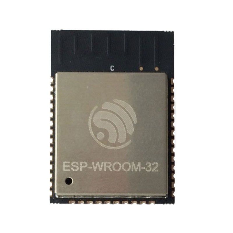
ESP-WROM-32:
The ESP-WROOM-32 is a compact and versatile Wi-Fi and Bluetooth module that integrates a dual-core processor, Wi-Fi, Bluetooth, and various input/output interfaces. The module is based on the ESP32 chip, which offers a range of features such as low power consumption, advanced peripherals, and built-in security protocols. The ESP-WROOM-32 module is designed to provide a complete solution for internet of things (IoT) applications, making it an ideal choice for developers looking to create innovative and connected devices. With its small size, low power consumption, and rich feature set, the ESP-WROOM-32 board is a popular choice for a wide range of IoT applications, from smart homes to industrial automation.
-
2.
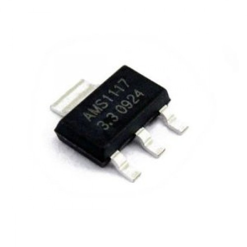
LM1117 voltage regulator:
The LM1117 is a versatile and widely used voltage regulator that provides a fixed output voltage with high accuracy and low dropout voltage. This regulator is capable of delivering up to 1A of output current and is available in a range of voltage options to suit different application requirements. The LM1117 voltage regulator is designed to operate with low input-to-output voltage differentials, making it ideal for use in battery-powered applications where low power consumption is critical. Its small form factor, low dropout voltage, and ease of use make the LM1117 a popular choice for a wide range of electronic circuits, including power supplies, battery chargers, and audio circuits.
-
3.
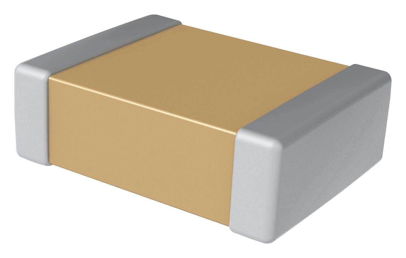
Capacitor 1206:
The Capacitor 1206 is a type of surface mount ceramic capacitor that is widely used in electronic circuits. This capacitor is named after its package size, which measures 3.2mm x 1.6mm x 0.8mm, making it larger than some other SMD capacitors. The Capacitor 1206 is designed to provide a high level of stability and reliability, with low losses and excellent temperature stability. Its small size and compatibility with automated assembly processes make it a popular choice for use in a wide range of applications, from consumer electronics to industrial automation. With its compact size and excellent performance characteristics, the Capacitor 1206 is a versatile and reliable component that is widely used in modern electronic designs.
-
4.
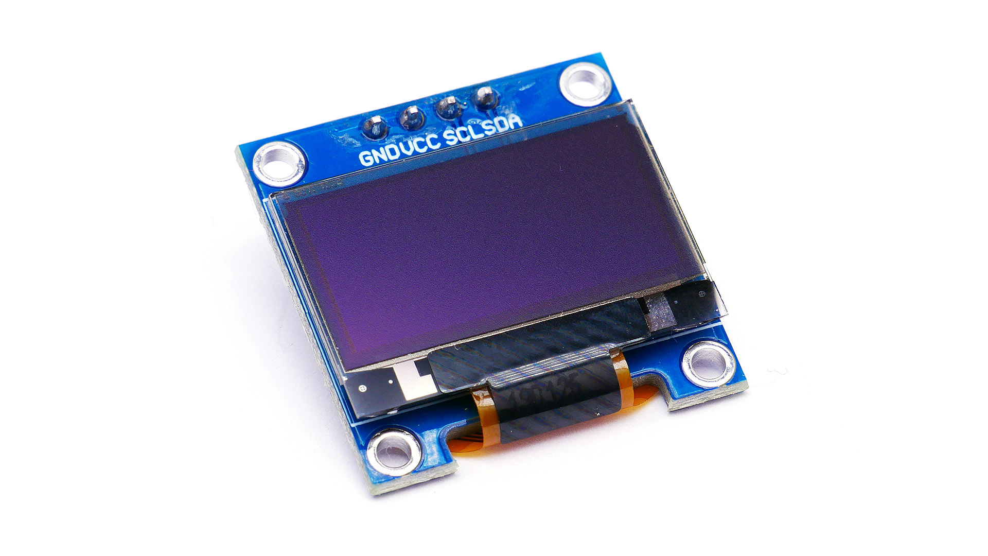
I2C OLED screen:
An I2C OLED screen is a compact display module that uses organic light-emitting diodes (OLEDs) to provide a high-contrast, high-resolution display. The I2C OLED screen uses the I2C (Inter-Integrated Circuit) communication protocol to interface with microcontrollers or other devices, allowing for easy integration into a wide range of electronic projects. These screens are available in a variety of sizes and resolutions, and their low power consumption and high visibility make them an excellent choice for battery-powered and portable devices. With its high-quality display and easy integration, the I2C OLED screen is a popular choice for a wide range of applications, including wearable technology, instrumentation, and home automation.
-
5.
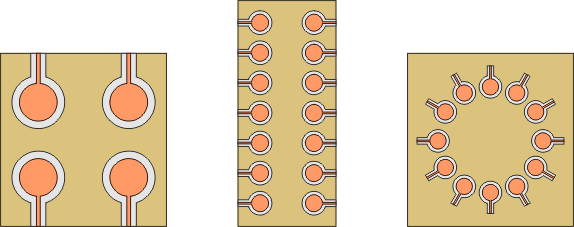
Touch pad designed on a PCB:
A touch pad designed on a PCB is a user interface that uses capacitive sensing to detect user input. The touch pad is integrated into the PCB design, allowing for a seamless user experience and reducing the need for external components. These touch pads are available in a range of sizes and shapes, and can be customized to meet specific project requirements. They are widely used in a variety of electronic devices, including mobile phones, laptops, and home automation systems. With its low power consumption, high sensitivity, and ease of use, the touch pad designed on a PCB is a versatile and reliable interface option for a wide range of electronic projects.
-
6.
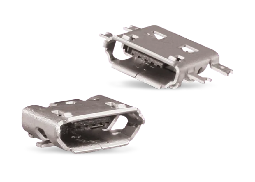
Micro USB Connector:
A micro USB connector is a small and compact interface that allows for data transfer and charging of electronic devices. It is a type of USB connector that is smaller than the standard USB port and is commonly used in portable devices such as smartphones, tablets, and portable hard drives. The micro USB connector has a five-pin design that supports USB 2.0 speeds and provides a reliable connection between devices. Its compact size and versatility make it a popular choice for portable electronic devices where space is limited. With its ability to provide power and data transfer in a small form factor, the micro USB connector is an essential component in many modern electronic designs.
-
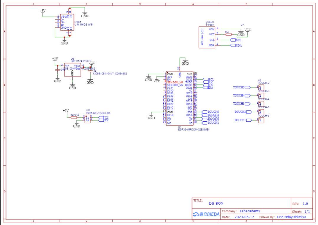
A schematic circuit:
is a graphical representation of an electronic circuit that shows the interconnection of components and their functions. It is a vital aspect of printed circuit board (PCB) design and provides a detailed overview of the circuit's structure and functionality. The schematic circuit uses standardized symbols to represent electronic components such as resistors, capacitors, and transistors, and lines to show how these components are connected. PCB designers use schematic diagrams to ensure that the electronic circuit functions as intended and to identify potential issues before manufacturing. With its ability to provide a visual representation of complex electronic circuits, the schematic circuit is an essential component in the design and development of modern electronic devices.
-
A Printed Circuit Board (PCB):
is a board made of insulating material, such as fiberglass or plastic, that provides a platform for mounting and interconnecting electronic components. The board contains a pattern of conductive tracks and pads that allow electrical signals to flow between the components. PCBs are used in almost all electronic devices and can be found in everything from computers and smartphones to cars and medical equipment. They are designed using specialized software and manufactured using a process that involves etching a copper layer and applying a series of layers of insulating material. PCBs offer several advantages over traditional wiring methods, including increased reliability, reduced assembly time, and improved performance. With its ability to provide a reliable and efficient platform for mounting and interconnecting electronic components, the Printed Circuit Board (PCB) has become an essential component in the design and manufacture of modern electronic devices.
-
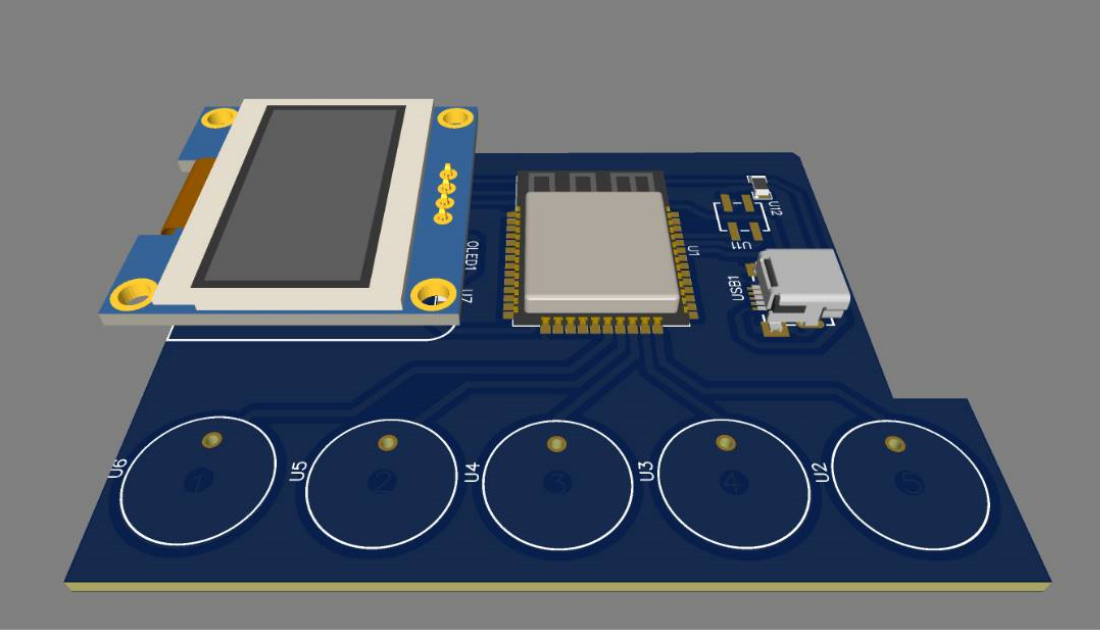
Hereafter is its 3D View:
-
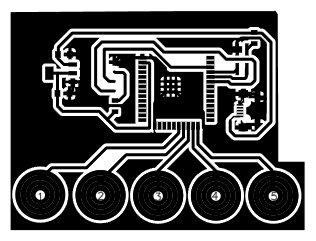
PCB's image for tracing:
-
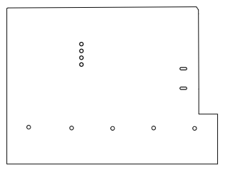
PCB's image for outlining:
-
PCB Milling files can be found here below:
-
XAMPP installation and ready-to-use web server environment
XAMPP includes the Apache HTTP Server, MariaDB (formerly MySQL) database, PHP, and Perl, collectively forming the acronym XAMPP. Apachefriends aims to simplify the setup and configuration of a local web development environment, allowing users to test and develop websites or web applications on their personal computers without the need for a dedicated server. It is compatible with various operating systems and offers a user-friendly interface for managing the server components. -
Download XAMPP:
Go to the official Apachefriends website and download the XAMPP package for your operating system (Windows, macOS, or Linux).
-
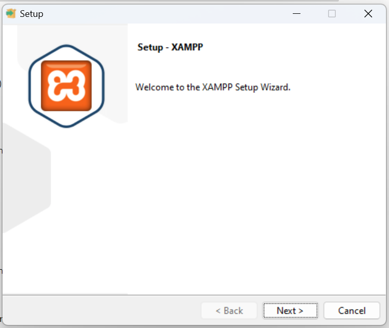
Install XAMPP:
Run the downloaded installer and follow the on-screen instructions to install XAMPP. Choose the components you want to install (Apache, MySQL, PHP, etc.) and select the installation directory.
-
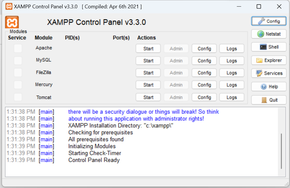
Run XAMPP:
Once the installation is complete, start XAMPP. On Windows, you can use the XAMPP Control Panel to start or stop the server components. On macOS and Linux, you can use the Terminal to start the necessary services.
-
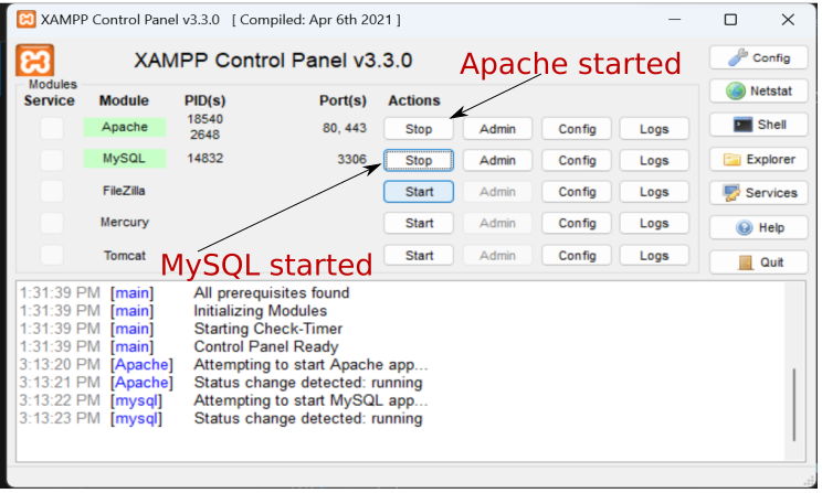
Start Apache and MySQL:
Here below I have to start Apache and MySQL in XAMPP in order to provide me with a local web server environment, allowing me to host and serve DsBOX web page (data visualization page) locally into my computer, as well as manage DsBOX’s database.
-
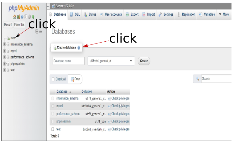
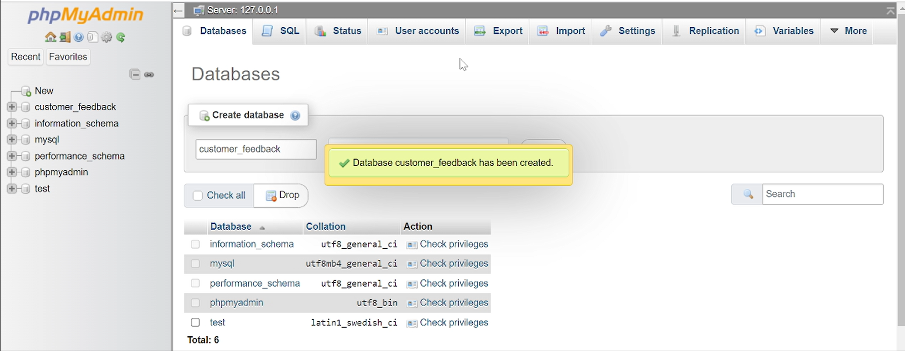
phpMyAdmin interface to create database of DsBOX
-
Then, customer_feedback database is created
-
The next step is to insert MySQL code:
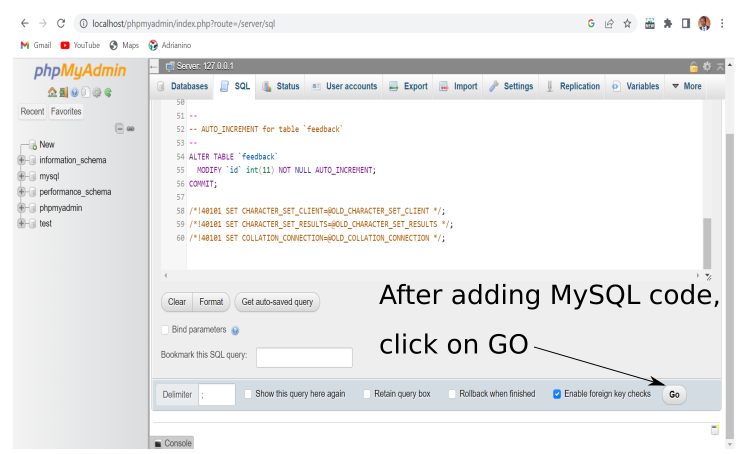
-
Here below is the used MySQL Database code
SET SQL_MODE = "NO_AUTO_VALUE_ON_ZERO"; START TRANSACTION; SET time_zone = "+00:00"; CREATE TABLE `feedback` ( `id` int(11) NOT NULL, `Q1` int(11) DEFAULT NULL, `Q2` int(11) DEFAULT NULL, `Q3` int(11) DEFAULT NULL ) ENGINE=InnoDB DEFAULT CHARSET=utf8mb4 COLLATE=utf8mb4_general_ci; ALTER TABLE `feedback` ADD PRIMARY KEY (`id`); ALTER TABLE `feedback` MODIFY `id` int(11) NOT NULL AUTO_INCREMENT; COMMIT; /*!40101 SET CHARACTER_SET_CLIENT=@OLD_CHARACTER_SET_CLIENT */; /*!40101 SET CHARACTER_SET_RESULTS=@OLD_CHARACTER_SET_RESULTS */; /*!40101 SET COLLATION_CONNECTION=@OLD_COLLATION_CONNECTION */; -
As shown here belo, MySQL code has been inserted:
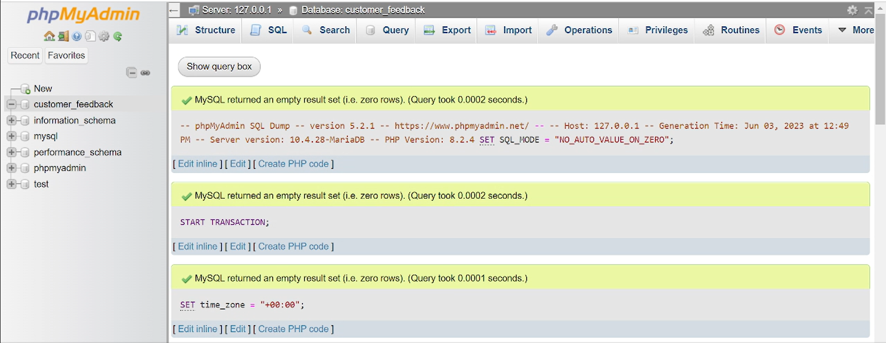
-
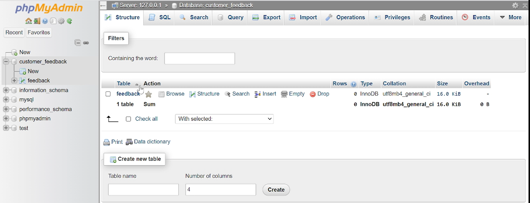
From the structure menu tab, here below is the flesh generated feedback table:
PCB Design:
Below here is the list of components to be used:
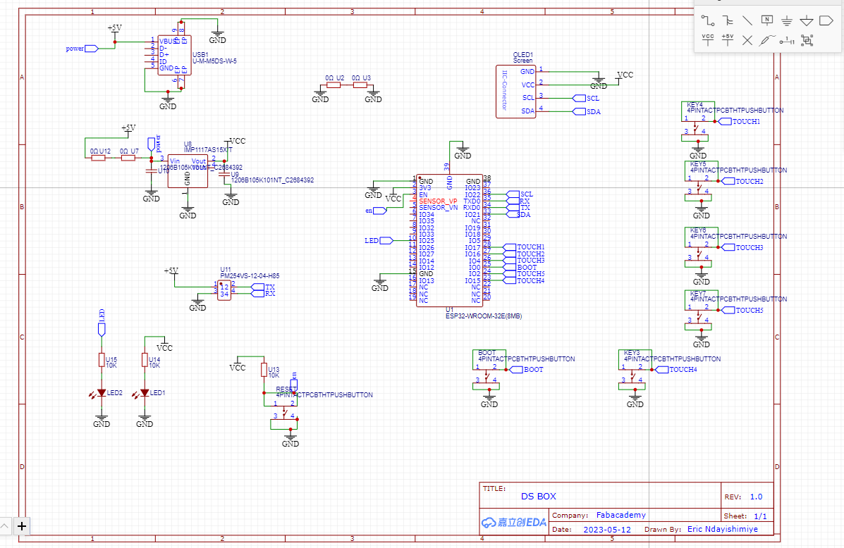
Here below is the schematic circuit of DsBOX
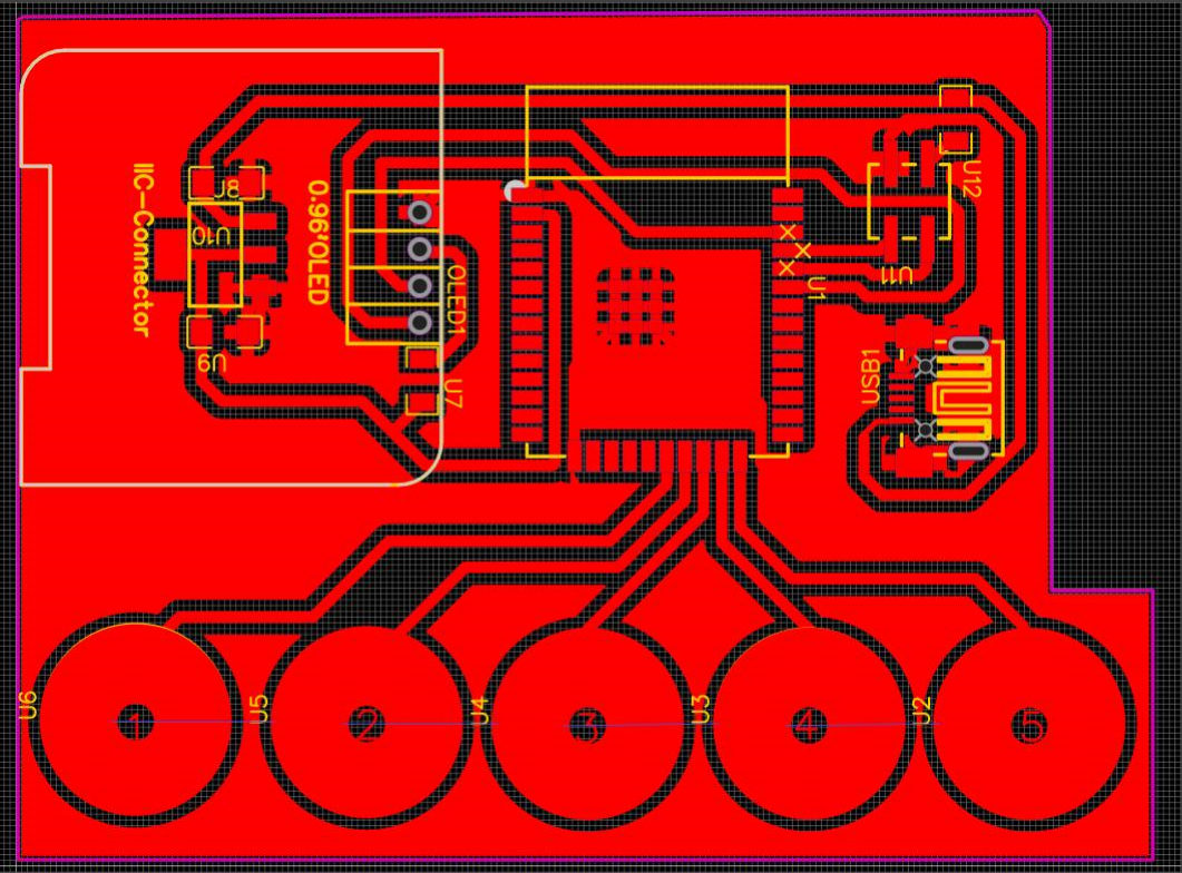
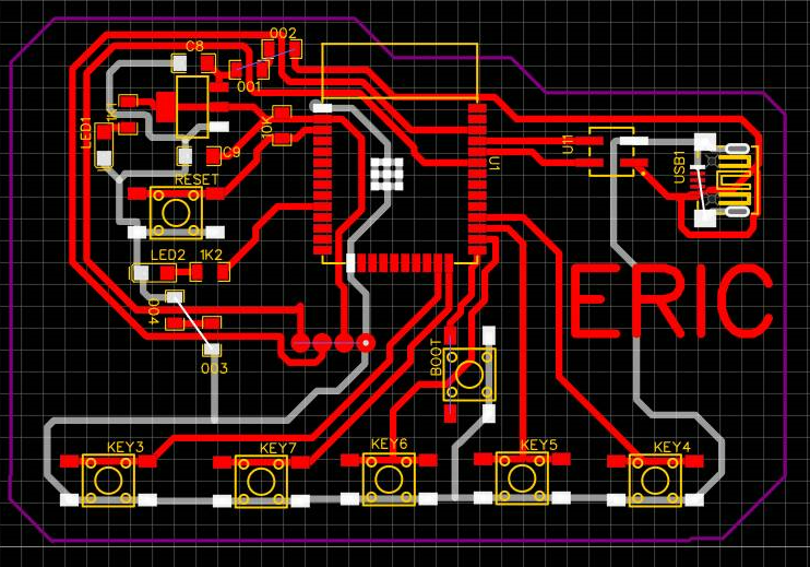
Down here is the then created PCB of DsBOX
After the PCB is designed, the subsequent stage involves generating a visual representation that indicates the drill lines used for generating the g-code utilized by the milling machine.
Following the previous step, the subsequent task involves generating the necessary g-code for our SRM-20 milling machines. To achieve this, I utilized MODS software to generate the toolpath.
Here below I am adding the double sided tape to fix the board on the bed of Roland SRM-20
After fixing the board on the bed, I fixed the milling tool
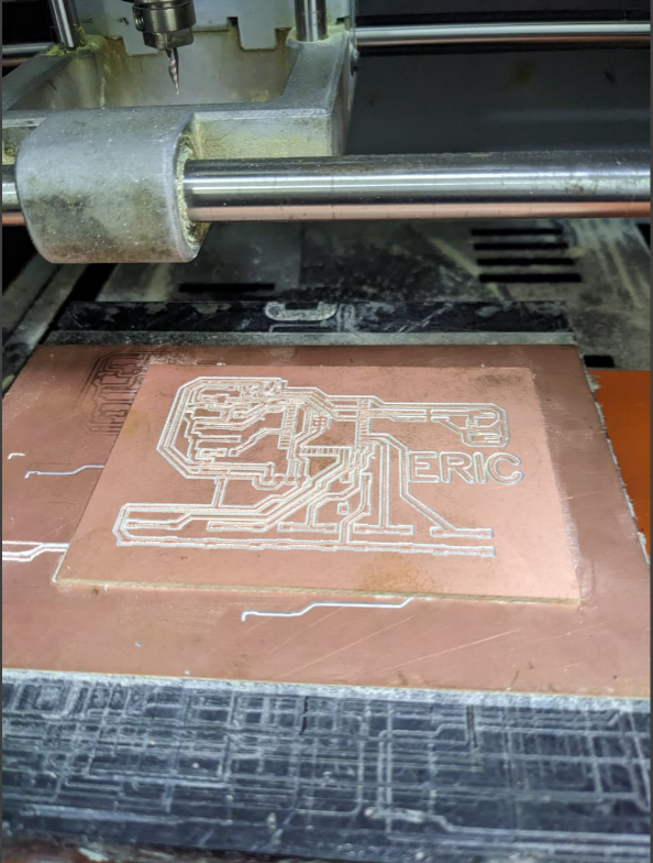
Cutting process
Extracting the created PCB
Removing copper around boutons to prevent mistakes on short circuit around them
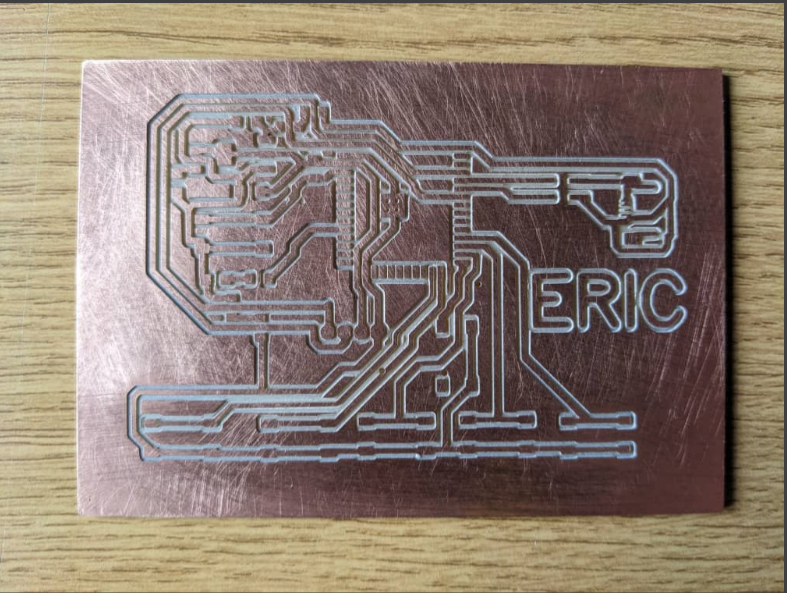
Here below is the made PCB for DsBOX:
Here below I am soldering and testing components
See here below the completed made PCB of DsBOX and its' electronic components
However, I encountered an unfortunate setback when the completed PCB of my project, the DsBOX, along with its electronic components, failed to function as intended. Faced with this challenge, I have made the decision to take a step back and redesign the PCB of the DsBOX from scratch. This decision was driven by my determination to overcome obstacles and create a fully functional and successful project.
Here below is the new circuit
Here below is the redesigned PCB for DsBOX:
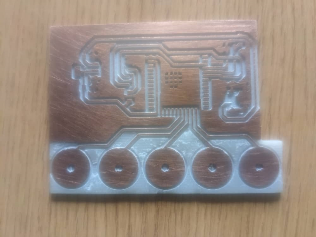
Here below is the redesigned PCB after milling in Roland SRM-20:
After countless efforts and dedication, I am elated to announce the successful production of the here below PCB of DsBOX.
Here below I am soldering electronic components on the board
Here below I am testing the circuit board
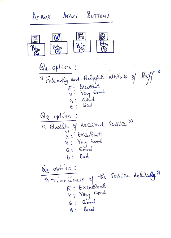
Here below is the pictorial/illustration of DsBOX Input Buttons to allow users give their feedback (rating) on Question (Qn) Option
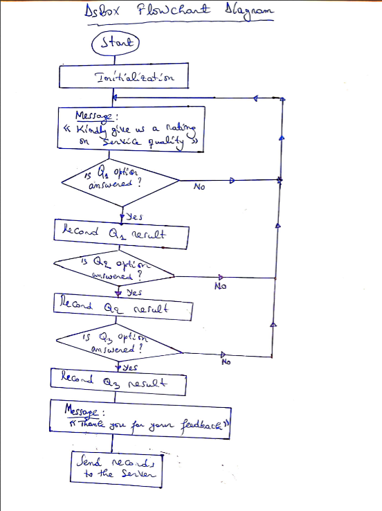
Here below is the DsBOX Flowchart Diagram
Here are the summarized steps to install and use XAMPP:
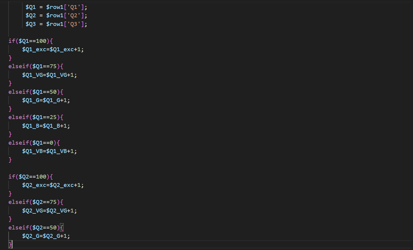
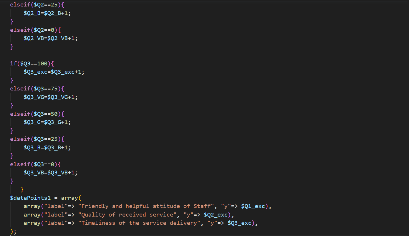
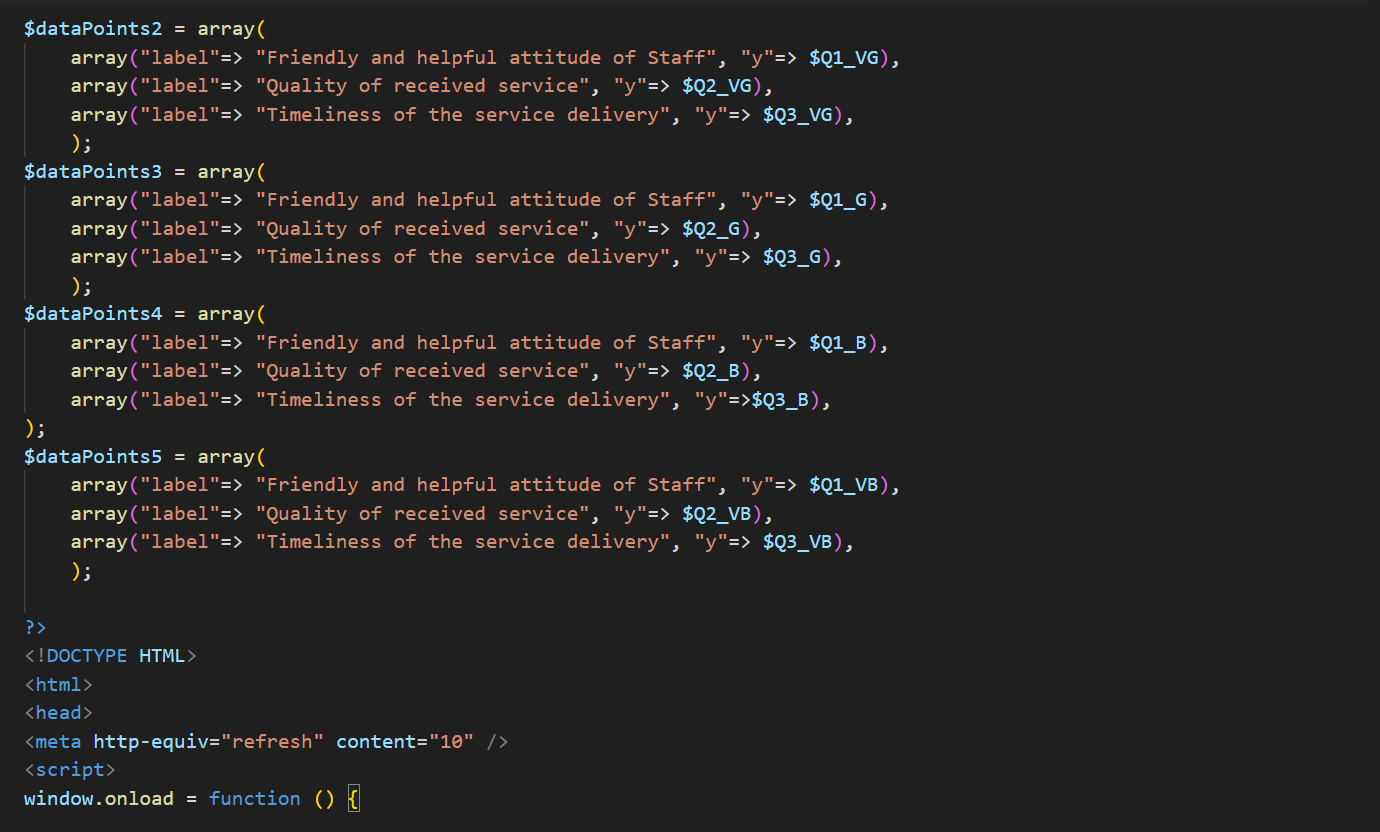
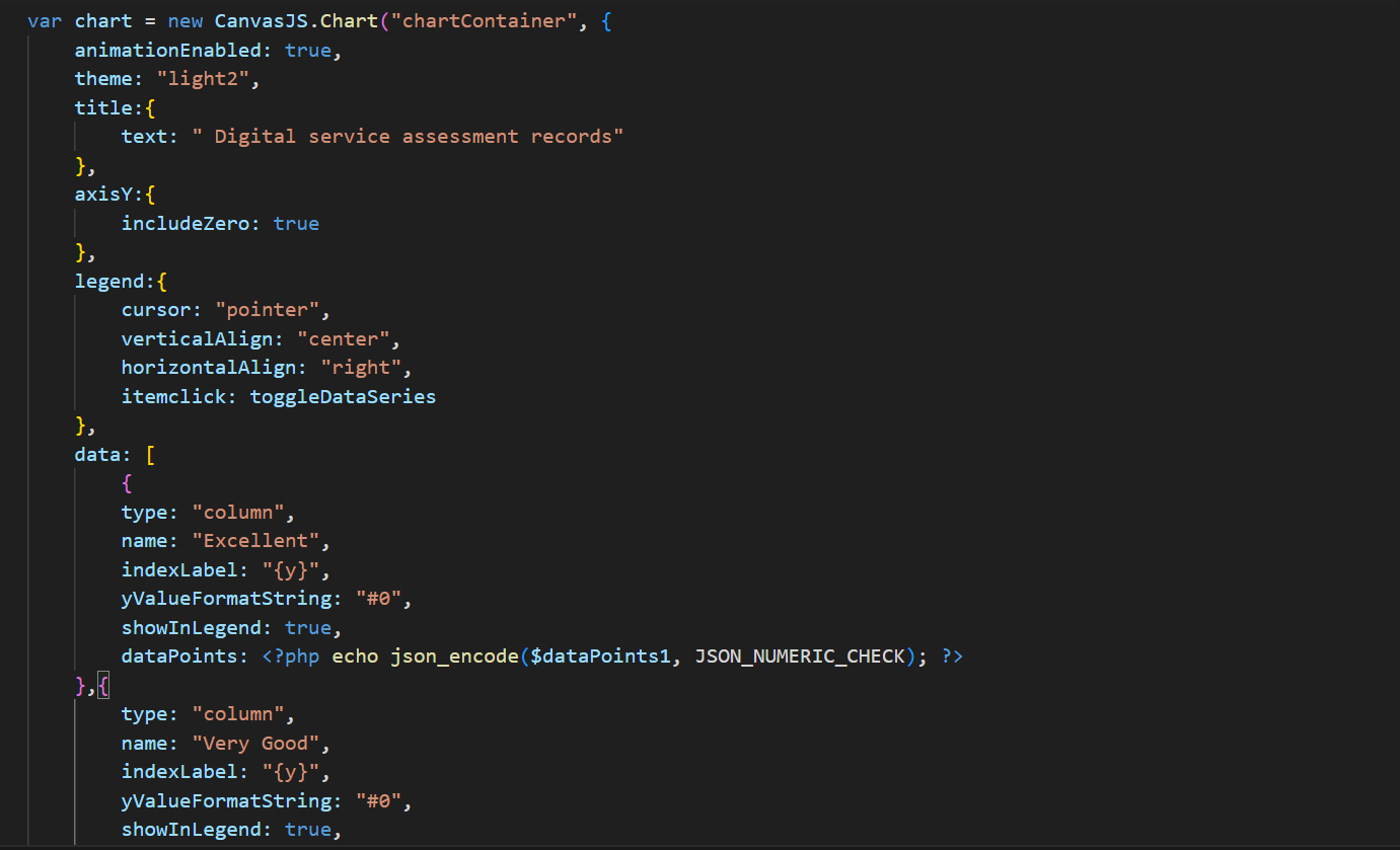
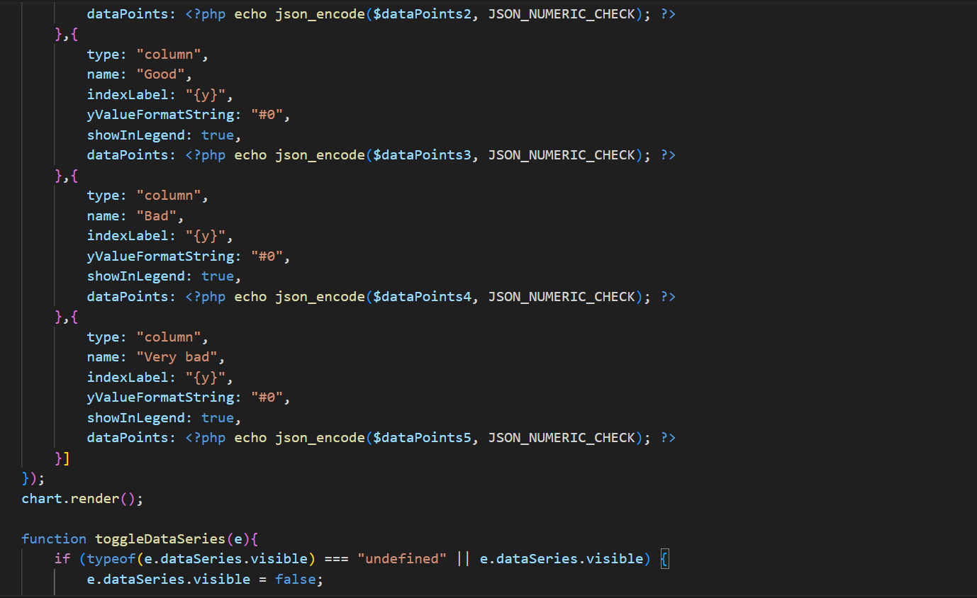
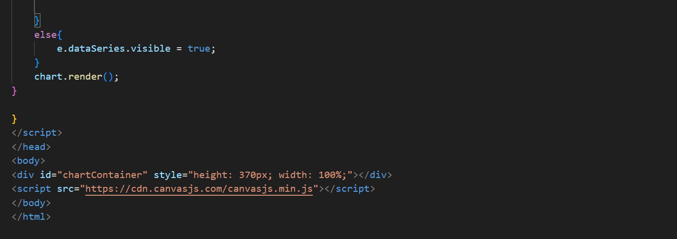
Here below is the User Interface code for DsBOX
I am going to use screenshots because there is a part of the code which is conflicting the html tabs (PRE & CODE) for displaying code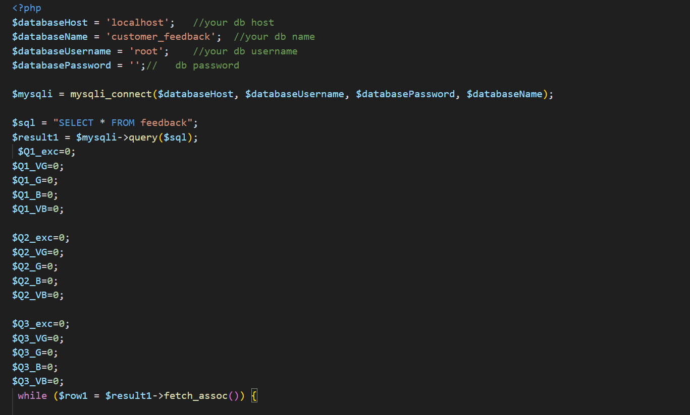
Setting up DsBOX front-end and back-end
Having XAMPP already installed in my computer: the "htdocs" directory in XAMPP is where I am going to place DsBOX front-end and back-end files to make them accessible and viewable through the local web server (my laptop), so that I can run DsBOX web application (frontend and backend) locally.-
DsBOX front-end and back-end files can be found here below:
-
-
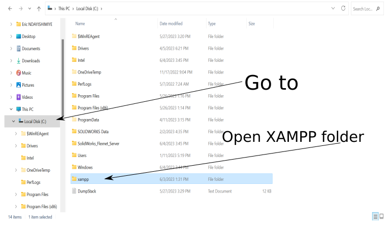
- Inside XAMPP folder, I look for htdocs folder and open it.
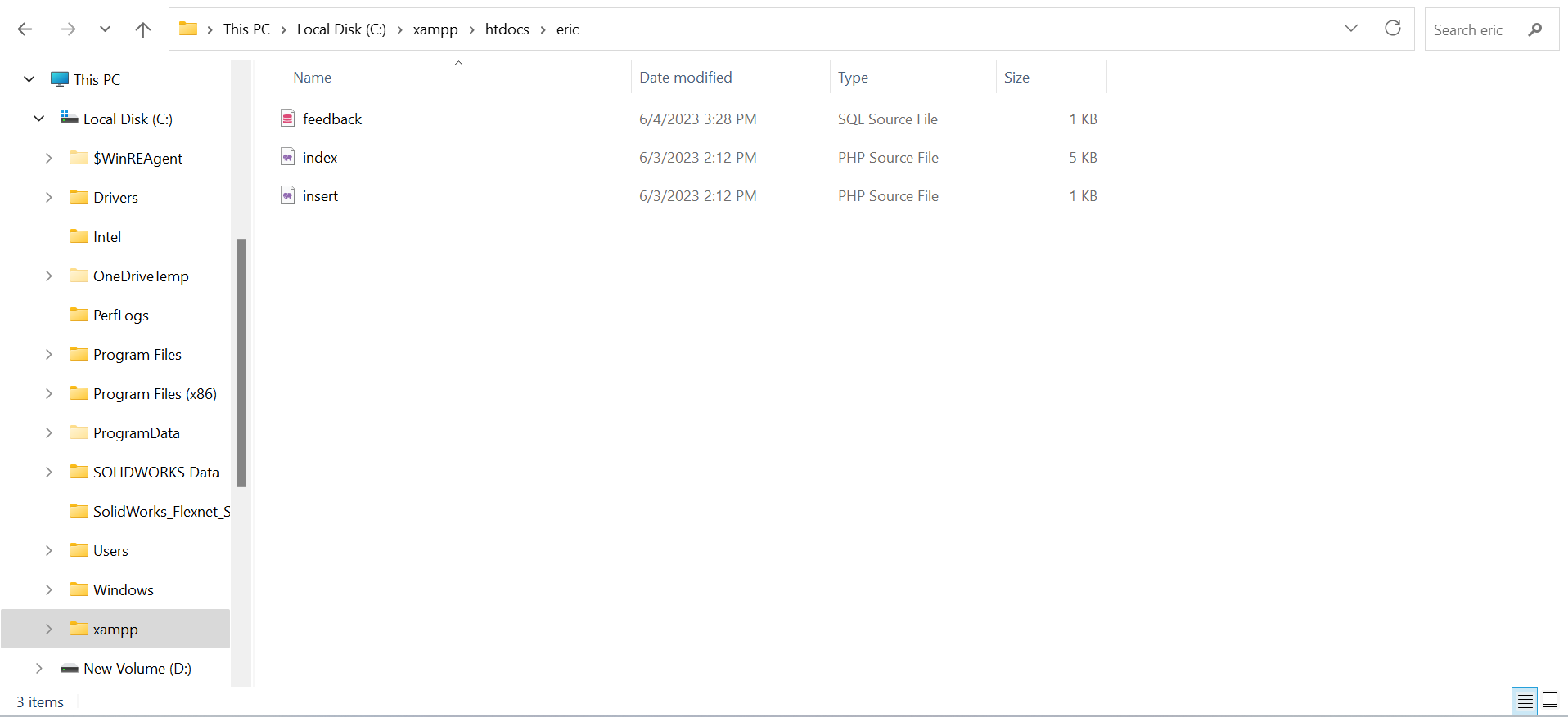
- Then, I Delete everything inside htdocs folder and put eric folder, containing DsBOX Font-End & Back-End Files.
-
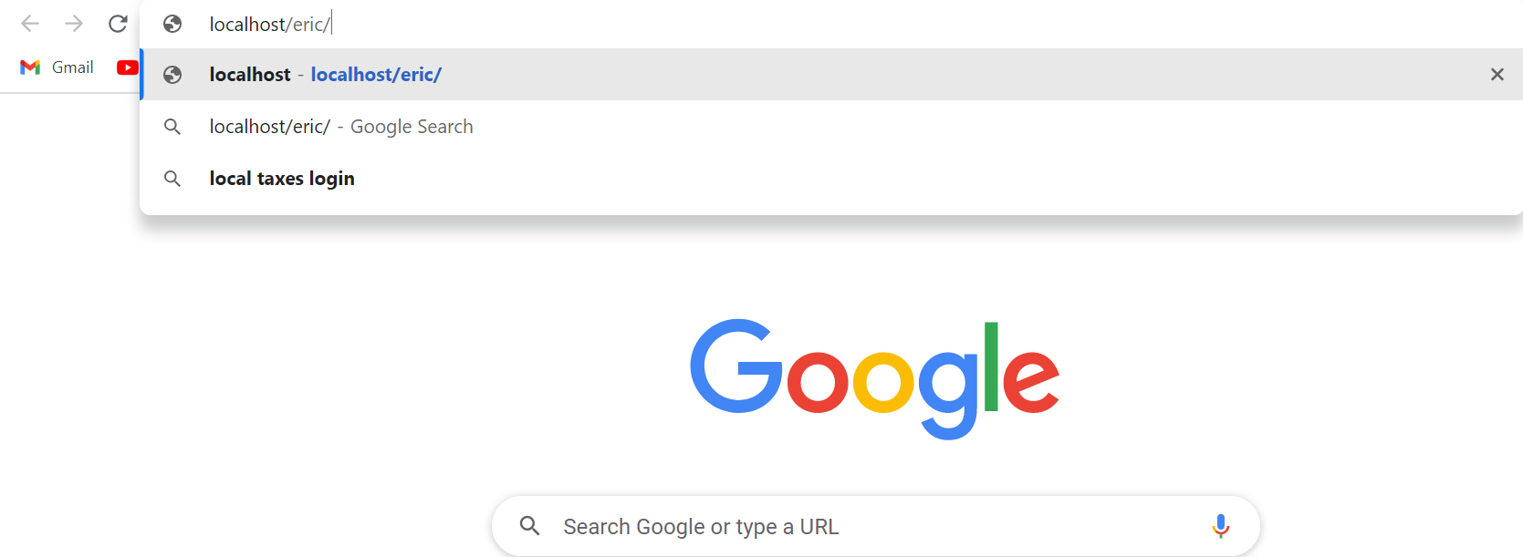
- So far, everything is done. Thus, I open-up the web brouser;
- In the web browser's Uniform Resource Locator (URL) address bar, I type localhost/eric
-
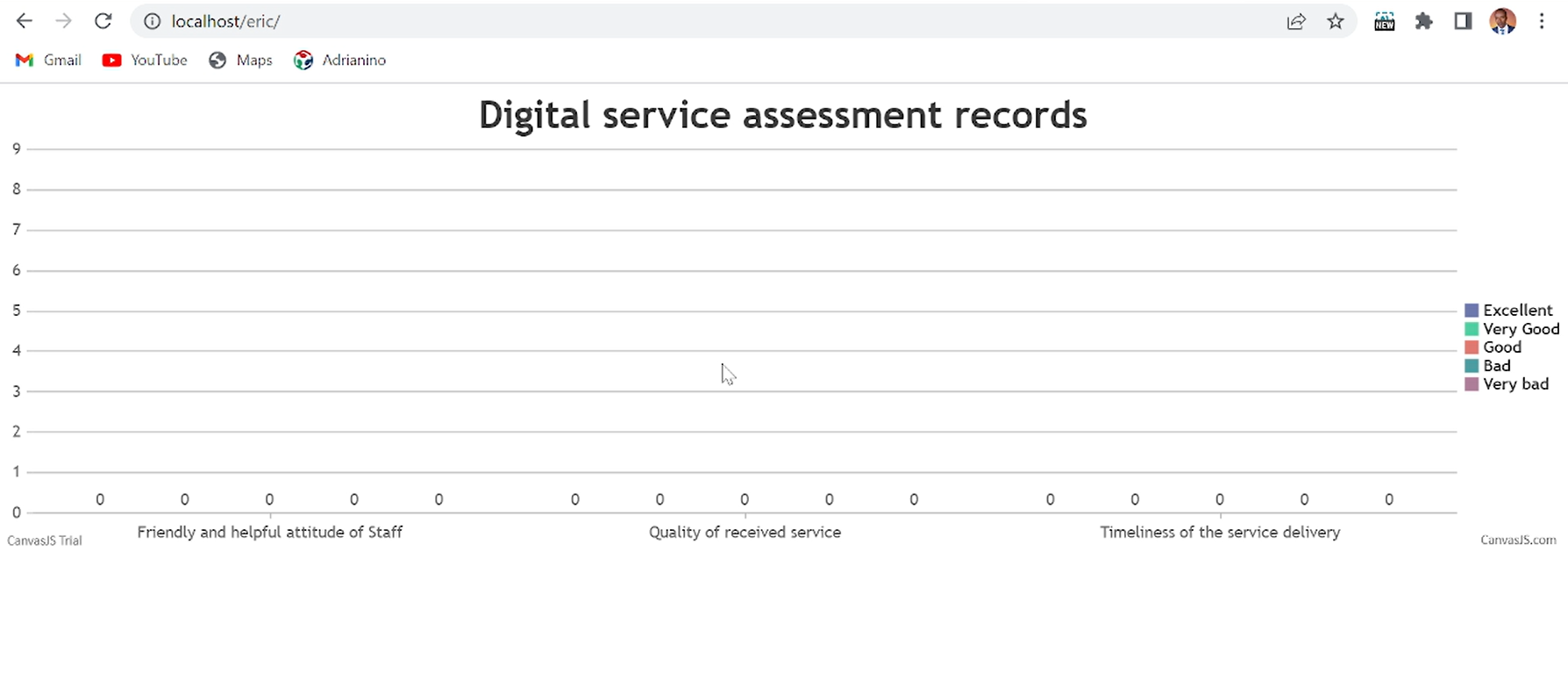
And finaly, I get the here below DsBOX's web interface
-
Here below is the API code for calling Arduino in order to send (insert) data into DsBOX
                        connect_error) {
            die("Connection failed: " . $conn->connect_error);
        }

        $sql = "INSERT INTO feedback (Q1, Q2, Q3)
        VALUES ('" . $Q1 . "', '" . $Q2 . "', '" . $Q3 . "')";

        if ($conn->query($sql) === TRUE) {
            echo "New record created successfully";
        }
        else {
            echo "Error: " . $sql . "
" . $conn->error;
        }

        $conn->close();


function test_input($data) {
    $data = trim($data);
    $data = stripslashes($data);
    $data = htmlspecialchars($data);
    return $data;
}
?>
Computer Aided Design of DsBOX housing
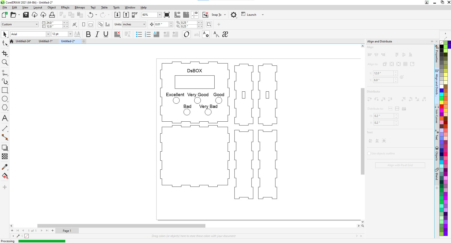
With the aid of Soldworks, the housing for DsBOX was designed.-
Here below is the DsBOX's housing parts
-
Cutting DsBOX housing parts using Epilog Laser machine
-
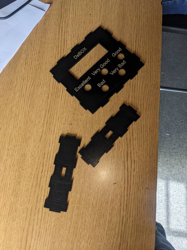
Here below is the cutted parts of DsBOX's housing
-
DsBOX's housing parts before wiring
-
Here below is the DsBOX's housing and wiring
Here below is the DsBOX code for operating ESP-WROOM-32
-
#include#include const char* ssid = "I_Am_Blessed"; const char* password = "Innovate!"; #include [] #include LiquidCrystal_I2C lcd(0x27,20,4); // set pin numbers const int Button1 = 15; const int led = 26; const int Button2 = 2; const int Button3 = 4; const int Button4 = 17; const int Button5 = 16; int buttonstate=0, prev=0; String ServerName="192.168.137.191"; int Q1_response=0,Q2_response=0,Q3_response=0, common_value=0, stage=0; void setup(){ Serial.begin(115200); lcd.init(); lcd.backlight(); pinMode(led,OUTPUT); pinMode(Button1,INPUT_PULLUP); pinMode(Button2,INPUT_PULLUP); pinMode(Button3,INPUT_PULLUP); pinMode(Button4,INPUT_PULLUP); pinMode(Button5,INPUT_PULLUP); WiFi.begin(ssid, password); Serial.println("Connecting"); while(WiFi.status() != WL_CONNECTED) { delay(500); Serial.print("."); wifi_msg(); } Serial.println(""); Serial.print("Connected to WiFi network with IP Address: "); digitalWrite(led,HIGH); Serial.println(WiFi.localIP()); wifi_connected(); delay(2000); Serial.println("Timer set to 5 seconds (timerDelay variable), it will take 5 seconds before publishing the first reading."); } void loop(){ if(stage==0){ q1_screen(); } delay(500); } //////////////////////////////////////////////////////////////////////////////////// /* getting response */ /////////////////////////////////////////////////////////////////////////////////////// int Responses() { int waiting=0; while(waiting ==0){ if(digitalRead(Button1)== LOW || digitalRead(Button2) == LOW|| digitalRead(Button3)== LOW || digitalRead(Button4)== LOW ||digitalRead(Button5)== LOW){ buttonstate=1; } else{buttonstate=0; prev=0;} if (digitalRead(Button1) == LOW && buttonstate==1 && prev==0 ){ Serial.println("Excellent Button pressed"); common_value=100; waiting=1; prev=1; } if (digitalRead(Button2) == LOW && buttonstate==1 && prev==0 ){ Serial.println("very good Button pressed"); common_value=75; waiting=1; prev=1; } if (digitalRead(Button3) == LOW && buttonstate==1 && prev==0 ){ Serial.println("Good Button pressed"); common_value=50; waiting=1; prev=1; } if (digitalRead(Button4) == LOW && buttonstate==1 && prev==0 ){ Serial.println("Bad Button pressed"); common_value=25; waiting=1; prev=1; } if (digitalRead(Button5) == LOW && buttonstate==1 && prev==0 ){ Serial.println("Very Bad Button pressed"); common_value=0; waiting=1; prev=1; } } return common_value; } //////////////////////////////////////////////////////////////////////////////////// /* Asking questions */ /////////////////////////////////////////////////////////////////////////////////////// //////////////////////////////////////////////////////////////////////////////////// /* sending feedback */ /////////////////////////////////////////////////////////////////////////////////////// void sendFeedback(String Q1,String Q2,String Q3) { sending_screen(); Serial.println(Q1+" "+Q2+" "+Q3); //Check WiFi connection status if(WiFi.status()== WL_CONNECTED){ HTTPClient http; String serverPath = "http://"+ServerName+"/eric/insert.php?Q1="+Q1+"&Q2="+Q2+"&Q3="+Q3; // Your Domain name with URL path or IP address with path http.begin(serverPath.c_str()); // If you need Node-RED/server authentication, insert user and password below //http.setAuthorization("REPLACE_WITH_SERVER_USERNAME", "REPLACE_WITH_SERVER_PASSWORD"); // Send HTTP GET request int httpResponseCode = http.GET(); if (httpResponseCode>0) { Serial.print("HTTP Response code: "); Serial.println(httpResponseCode); String payload = http.getString(); Serial.println(payload); digitalWrite(led,LOW); delay(300); digitalWrite(led,HIGH); delay(300); digitalWrite(led,LOW); delay(300); digitalWrite(led,HIGH); delay(300); //check for success server response if(httpResponseCode == -1){ lcd.clear(); lcd.setCursor(2, 1); lcd.print("DATA RECORDED"); lcd.setCursor(2, 2); lcd.print("THANK YOU "); } delay(3000); stage=0; loop(); } else { Serial.print("Error code: "); Serial.println(httpResponseCode); if(httpResponseCode == -1){ lcd.clear(); lcd.setCursor(2, 1); lcd.print("server error"); lcd.setCursor(2, 2); lcd.print("Try again later.. "); } delay(3000); loop(); } delay(500); // Free resources http.end(); } else { Serial.println("WiFi Disconnected"); //error lcd.clear(); lcd.setCursor(2, 1); lcd.print("wifi"); lcd.setCursor(2, 2); lcd.print("Disconnected"); delay(3000); } stage=0; } void q1_screen(){ lcd.clear(); lcd.setCursor(0, 0); lcd.print("How was Friendly and"); lcd.setCursor(0, 1); lcd.print("helpful attitude of"); lcd.setCursor(0, 2); lcd.print("Staff?"); Serial.print(""); Serial.print("How was Friendly and helpful attitude of Staff?"); Q1_response=Responses(); delay(1000); q2_screen(); stage=1; } void q2_screen() { lcd.clear(); lcd.setCursor(0, 0); lcd.print("How was Quality of"); lcd.setCursor(0, 1); lcd.print("received service ?"); Serial.println(""); Serial.print("How was Quality of received service ?"); Q2_response=Responses(); delay(1000); q3_screen(); } void q3_screen() { lcd.clear(); lcd.setCursor(0, 0); lcd.print("How was Timeliness"); lcd.setCursor(0, 1); lcd.print("of the service"); lcd.setCursor(0, 2); lcd.print("delivery?"); Serial.println(""); Serial.print("How was Timeliness of the service delivery?"); Q3_response=Responses(); delay(1000); sending_screen(); sendFeedback(String(Q1_response),String(Q2_response),String(Q3_response)); stage=0; Q1_response=0; Q2_response=0; Q3_response=0; } void sending_screen(){ lcd.clear(); lcd.setCursor(2, 1); lcd.print("THANK YOU FOR"); lcd.setCursor(2, 2); lcd.print("YOUR FEEDBACK"); } void wifi_msg(){ lcd.clear(); lcd.setCursor(2, 1); lcd.print("CONNECTING "); lcd.setCursor(2, 2); lcd.print("TO WIFI.."); } void wifi_connected(){ lcd.clear(); lcd.setCursor(2, 1); lcd.print("WIFI"); lcd.setCursor(2, 2); lcd.print("CONNECTED"); }
DsBOX Final testing
-
Here below are DsBOX's project files
Thank you!
Eric NDAYISHIMIYE, FabLab Rwanda.