3. Computer controlled cutting
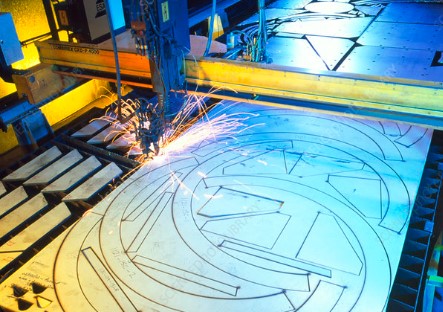
This week is all about computer controlled cutting. The FABLAB machines we will explore in this week's task are Vinyl Cutter and Laser Cutter. Computer controlled cutting is a computer controlled router related to the hand held router used for cutting various hard materials such as wood, composites, aluminium, steel, plastics and more.Vinyl cutter is used for cutting sticker papers primarily, where as laser cutter is used for cutting anything from a paper to leather to cardboard, pdf, acrylic, etc. Even CNC routers that cut MDFs and Plywoods come under computer controlled cutting if I am not wrong. Also the industrial metal laser cutter and engravers.
Exploring Vinyl Cutter at riidl
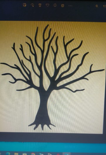
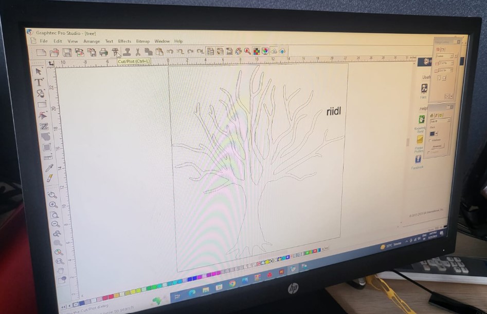
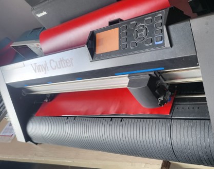
For this week's assignment, we have to design and cut something on a vinyl cutter. Before that, let's understand a bit about a vinyl cutter. So the Vinyl cutter we have at riidl is from GRAPHTEC called Cutting Plotter CE7000. So according to wikipedia, Computer designed vector files with patterns and letters are directly cut on the roll of vinyl which is mounted and fed into the vinyl cutter through USB or serial cable. Vinyl cutters are mainly used to make signs, banners and advertisements. In regards to that, we tried to print a simple tree structure that I wanted to put as a vinyl sticker on my tablet.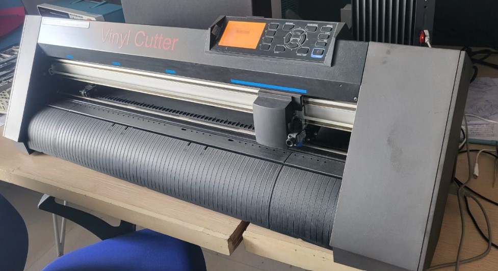
The process:
Step 01: Design
Ofcourse you need to design first. I used corel draw software to create a dxf file. So if we start from the beginning, I browsed a nice jpeg on google to find a nice photo I want. THen pasted it into coreldraw and converted it into vector. I gave it a small touch by editing its edges a bit and exported the file in dxf format. (The details of using corel draw and/or similar software is explained in Week 2 Computer aided Design page)
Step 02: Installing the software
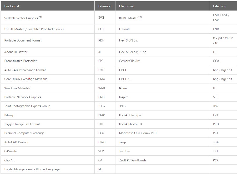
You need to download the Vinyl cutter software called Graphtec Pro Studio here. All possibilities and features of the software are intuitively explained on the same website linked above. It accepts various file formats as mentioned below:
Step 03: Importing the File
File > open > select File
Once the file is open, you make sure with the dimensions if they are within the size. You can also add text or simple drawings/figures by directly designing them in the software.
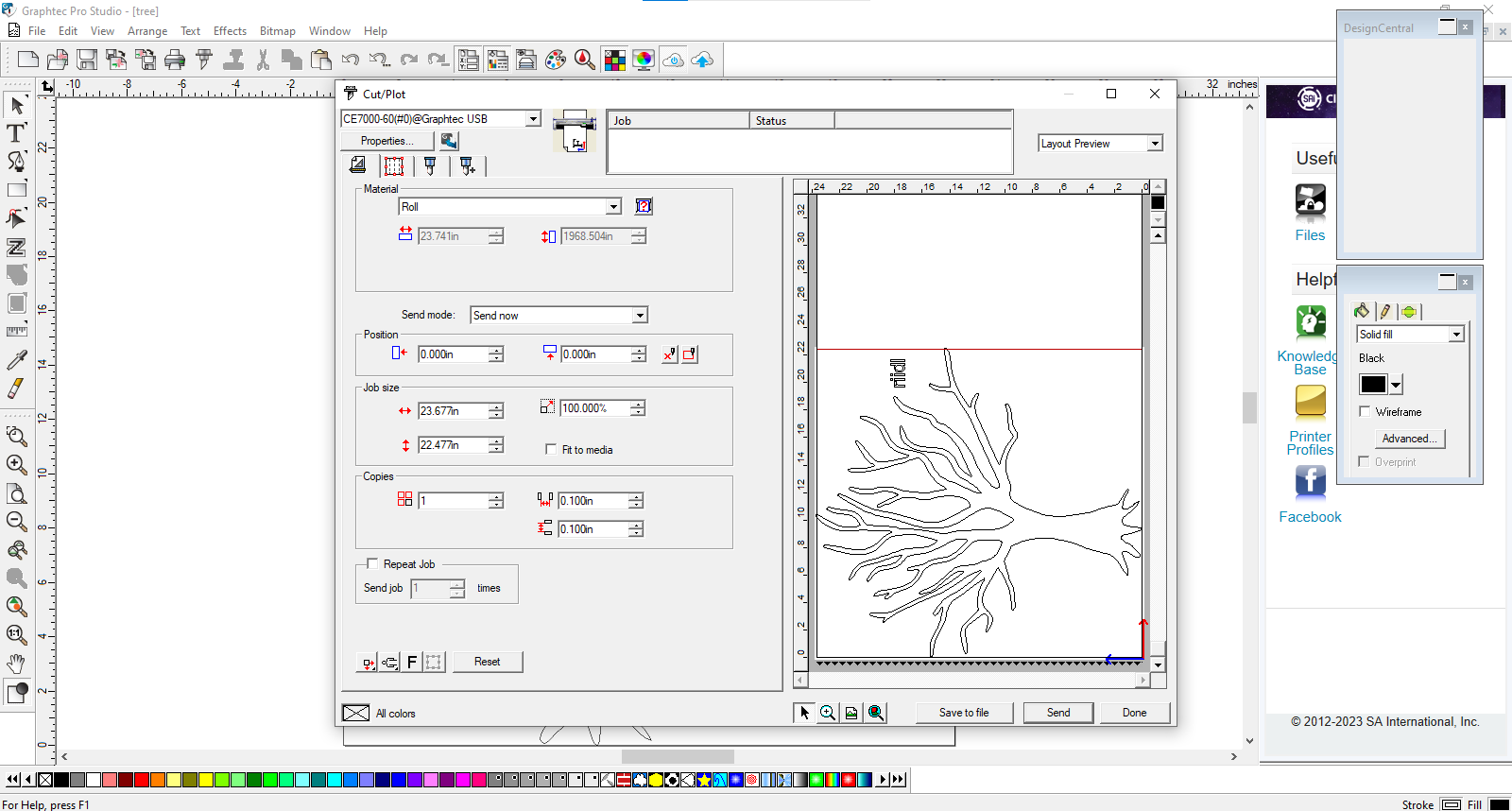
Step 04: Cut/Plot dialog box
Once the cut file is ready, you click on the cut/plot option. You need to set and verify the basic specifications here such as type of material input (roll in this case), end to end dimensions, position and number of copies needed. You also see the preview in the right side window to estimate the size.
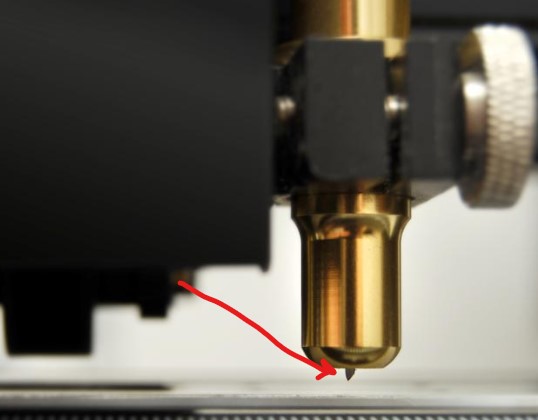
Step 05: Set the knife
You need to make sure and properly set the knife of the vinyl cutter so as to get the cut through the top layer of the vinyl material. Setting the knife is very easy and is done by just adjusting the screw on the knife tool.
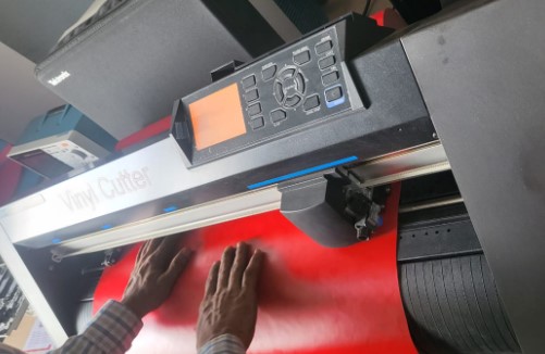
Step 06: Putting the sheet in
You need to manually insert the vinyl sheet into the machine as shown in the figure below:
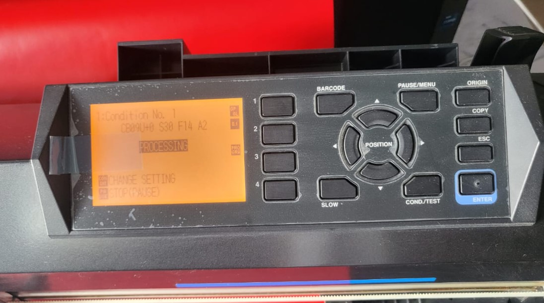
Step 07: Start the cutting
Once you start the cutting, initially the paper roll will be passed through without cutting only to estimate the total size it is going to use. Then it pulls the paper back and then starts actual cutting as shown in the figure below:
Step 08: Removing the cut part
The cut part is supposed to be removed carefully using twissers if needed. I was in a hurry and did the mistake to do it carelessly and ended up tangling the tree branches as shown: But the negative side of the cut was intact and infact it can also be used as a sticker.
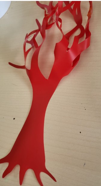
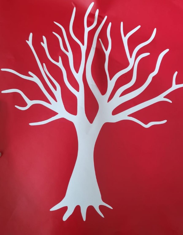
Also learnt a lesson how difficult it is to handle and stick small vinyl cuts. For example, the riidl fon I tried next to the tree. It turns out negative vinyl cutting is more easier in case of text.
Understanding the laser cutter at riidl
Let's start with the basics to understand laser cutting and the machine itself.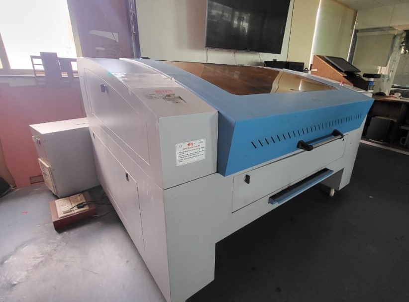
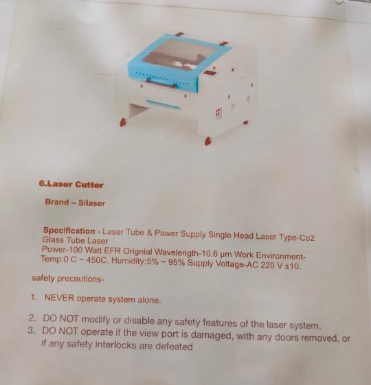
I have used the laser cutting machine especially the one in the riidl FABLAB since years. So I am kind of well equipped with it's power, speed and tolerances with respect to paper, mdf, acrylic and leather to some extent, in case of both cutting as well as engraving. Our laser cutter machine at riidl is a CO2 Laser cutter from SIL (Suresh Indu Lasers Pvt. Ltd). The details of the same are as follows:
Laser cutting is a technology that uses a laser to vaporize materials, resulting in a cut edge. While typically used for industrial manufacturing applications, it is now used by schools, small businesses, architecture, and hobbyists. Laser cutting works by directing the output of a high-power laser most commonly through optics.
Types of Laser cutters
The three main types of laser cutters are as follows:Materials: Glass, plastics, leather, wood, and acrylic.
Materials: Plastics, Metals, and Ceramics.
Materials: Metals and Organic materials.
Understanding Laser Cutter characteristics
To recaliberate the lasercutter charateristics with my partner Jesal, we worked on the following points to test.1. Focus
When laser cutting, the focal point is critical in ensuring that the maximum amount of available energy produced by the tube reaches the work piece. If you are “out of focus” then the machine will not cut as effectively, as you are lessening the effect of the beam on the part
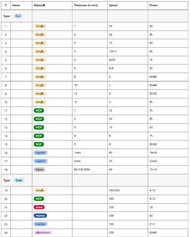
2. Power x Speed settings
A laser's power is independent of its speed, although a perfectly balanced combination of the two is essential for optimal results. High Speed Low Power is basically engraving v/s Low Speed High Power is Cutting. The chart of speed and power for specific thickness materials is prepared at riidl as shown below:
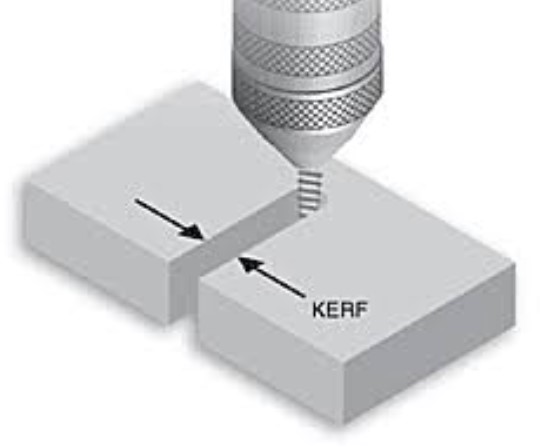
3. Kerf
The laser burns away a portion of material when it cuts through. This is known as the laser kerf and ranges from 0.08mm – 1mm depending on the material type and other conditional factors.
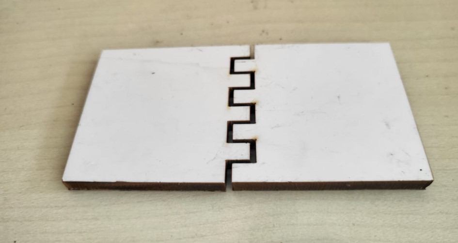
4. Joints and joint clearance
Finger joints (AKA box joints), mortise and tenon joints, and slotting joints are the most commonly used with laser cut structures, because they’re very simple and sturdy. For joint clearance fit or interference fit, your need to analyse your laser cutter machine efficiency by trial and error.
Parametric design kit
Next half of this week's assignment is to design, lasercut and document a parametric construction kit.Step 1: Ideation
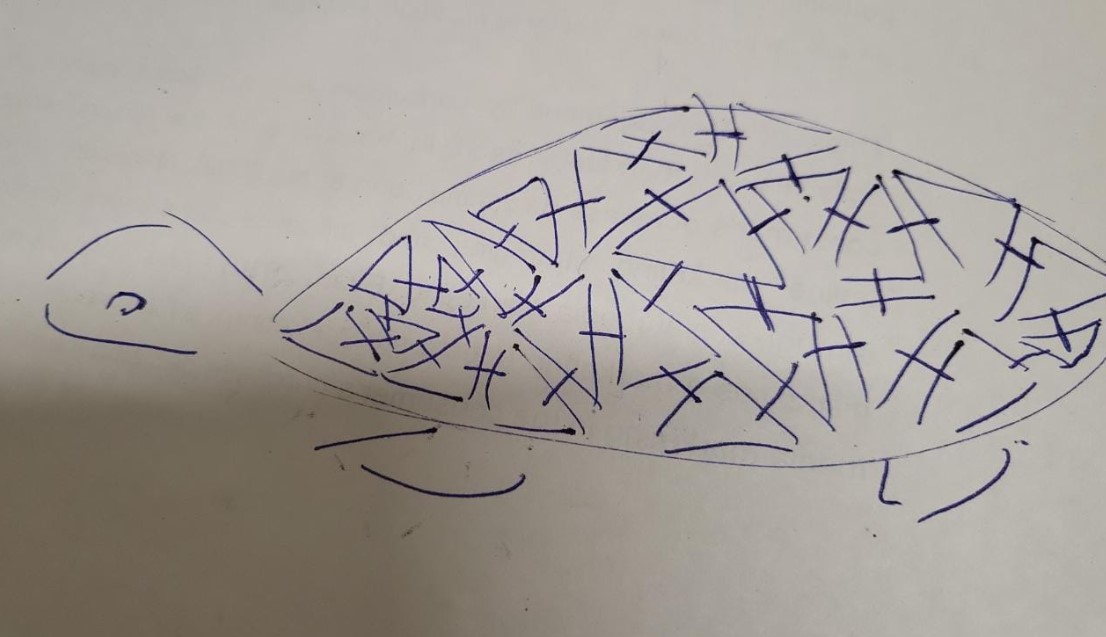
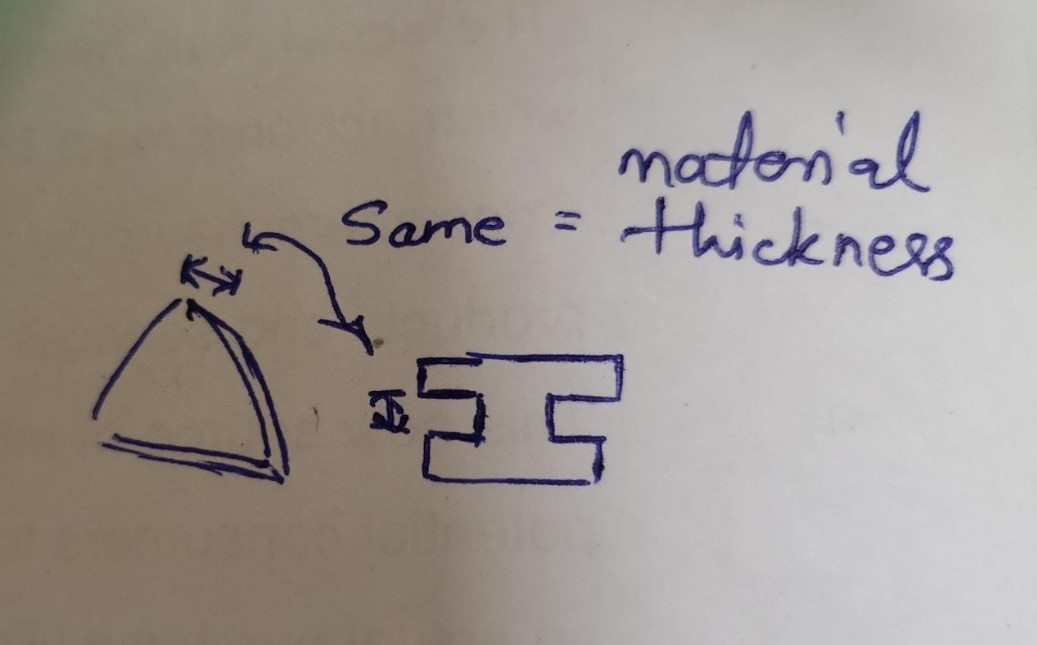
After thinking hard about wht exactly I want to do as a parametric design kit, inspired by a turtle shell design, I decided to try out a triangular parametric design kit. The initial ideation and plan is shown in the figure below:
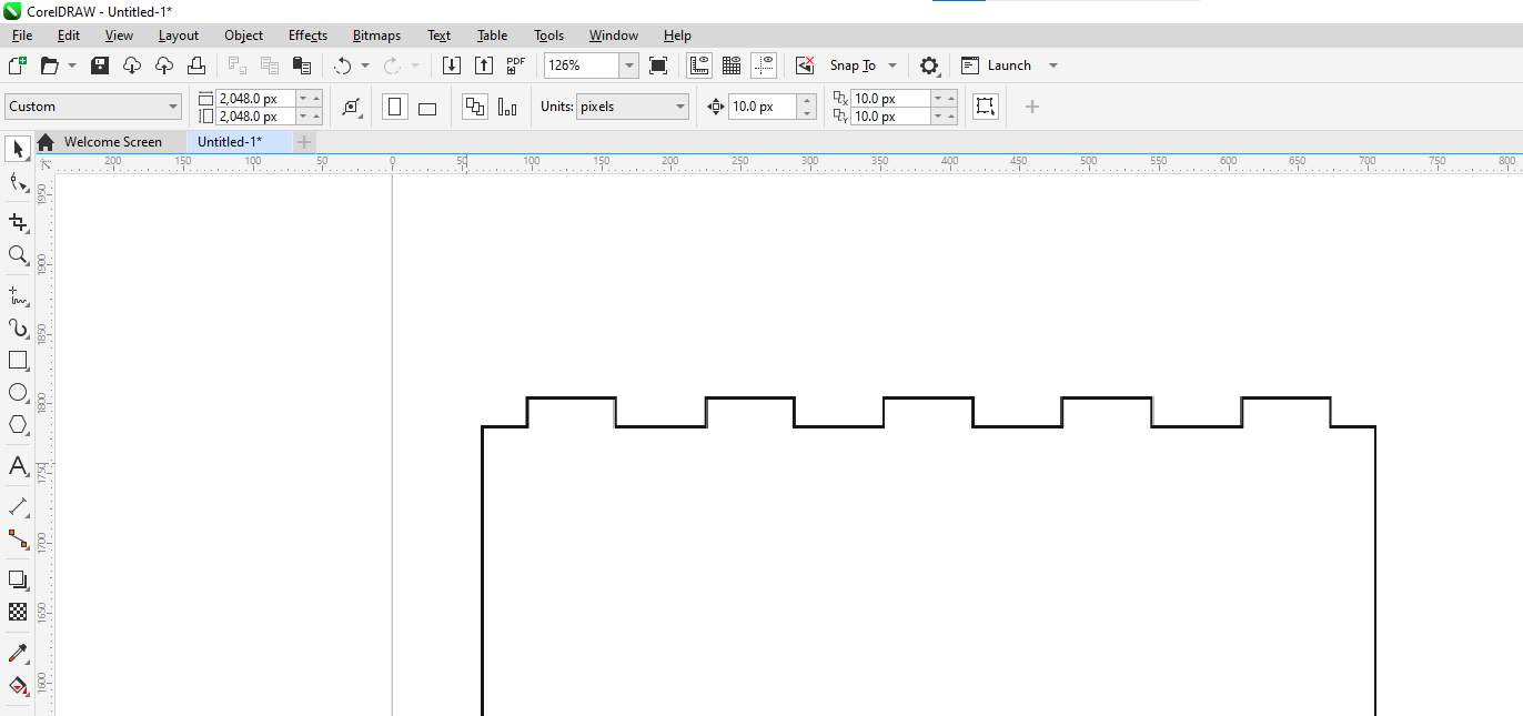
Step 2: Design
Next step was to design it on the RDworks software, try it out with respect to the laser kerf for a perfect joint. Design can also be made on other vector based softwares like Corel Draw, Illustrator or Fusion or Solidowrks, but I designed it directly on the RDWorks software.
Step 2a: Installing RDWorks
RUIDA RDWorks is a software used for controlling laser engraving and cutting machines manufactured by RUIDA Technology. The software provides users with a graphical user interface to create, edit and execute laser engraving and cutting jobs. It is compatible with a wide range of vector formats including DXF, AI, PLT, and DST. The RDWork v8/LaserWorks v8 system supports the following formats: Vector format: Dxf, ai, plt, DST, dsb, and related formats. Bitmap format: BMP, jpg, gif, png, mng, and related formats. RDWorks can be installed at the link here: RDWorks V8 Download
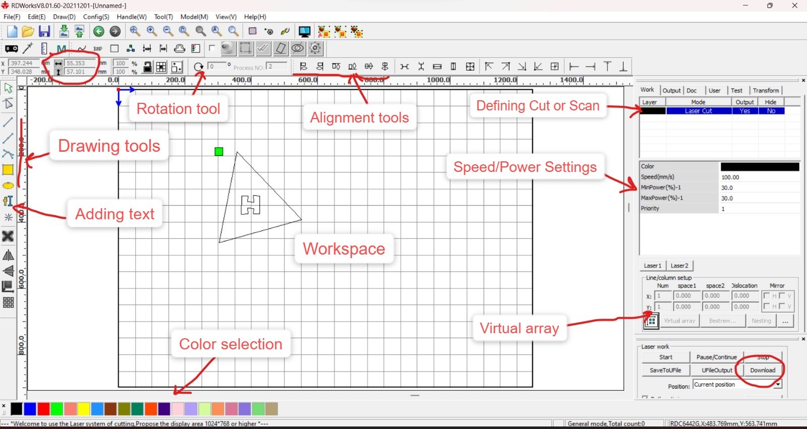
Step 2b: Exploring RDWorks
The interface RDWorks software is quite intuitive. A quick overview of the same is shown below:
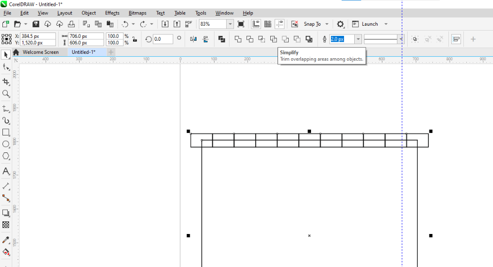
Step 2c: Making virtual array
To duplicate the cuts, we can use virtual array option with linear patterns your selected design the number of times your enter in both X axis as well as Y axis as shown below:
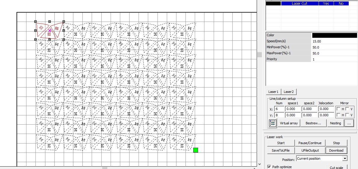
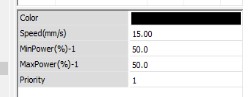
Step 2d: Setting power and speed
You need toset the speed and power here. The material I used was sunboard 5mm thick and thus accordingly speed and power values as shown below: By the way, the sunboard I used is reused material as a part from already used up decorative material for some event at riidl. It is really a good way to reuse these one time use decorative/promotional printed sunboards to reuse for such experimentations or projects
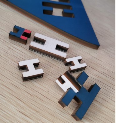
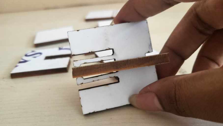
Step 3: Kerf test cut
For the testing of the fitting betweeen two triangles and the connector, I first experimented by just printing the connectors with different sizes as shown below:
The best fit dimension for a tight fit of 5mm thick sunboard was 4.3mm width. So we can estimate that the kerf is around 0.35mm for the laser cutter at riidl. If wondering how it was calculated, then
[Thickness (5mm) - tight fit dimension (4.3mm)]/2 = Kerf (0.35mm)
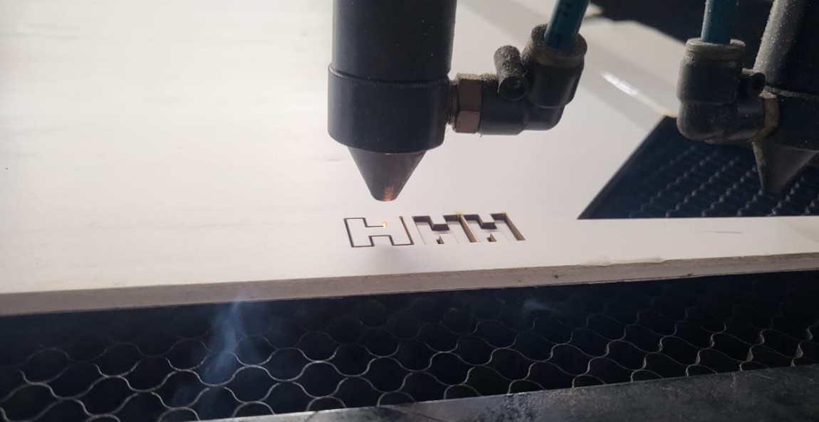
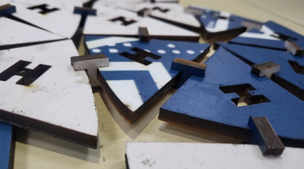
Step 4: Cutting everything and assembly
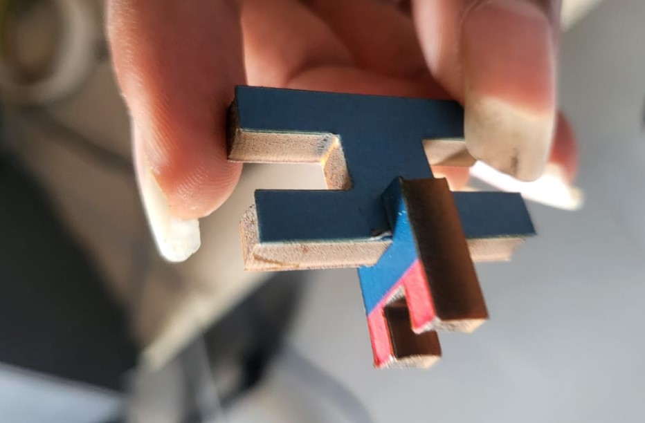
So after cutting all the triangles and connectors, its time to try and build something out of it. The thinking behind the design was to be able to achieve dome like structures by connecting these triangles using H connectors. It kindoff didn't workout completely well but here's what it looked like when partially assembled.

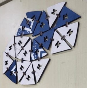
Step 5: Final Image
The curvy dome was not achieved to the full extent. But here's what it looks like:
Step 6: Future Advancements
Based on the above experimentation, it was evident that if you want a 3D curvy shape, H connectors are not the right ones. You need a spoke connector that can be attached at multiple angles, thus providing the necesarry curve to the overall structure. If I get time later, it is sure worth trying out again.
Group Work
For focus, everyone around uses 6mm and/or the thumb rule, but yes the same is not true always. So lets define it!My friend Jesal was well equipped with the process, so here's what we did to find the zone of focus and to look at the defocussed beam diameters.
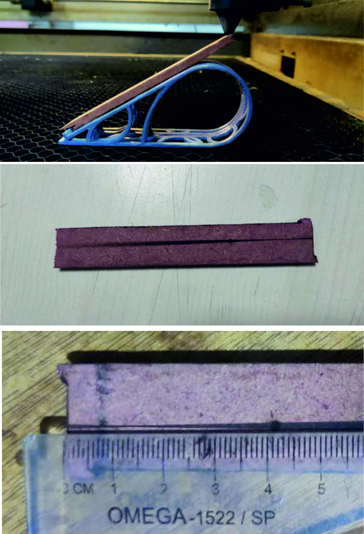
So basically how it works is based on the math of 30-60-90 triangle trignometry.
From basic trigonometry, in a 30-60-90 triangle, the side opposite the 30 degree angle is 1/2 the length of the hypotenuse. A specific beam width or best focus can thus be pinpointed by measuring the point's distance from the edge and halving it to give the required height. More description of this technique can be found here
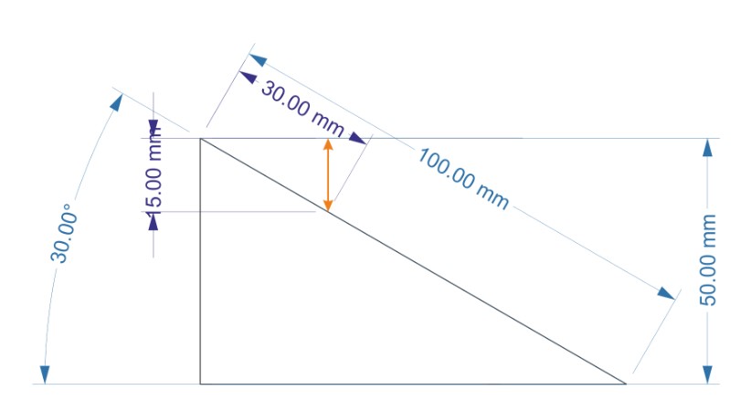
The zone of best focus is at around the 12 mm mark on the scale, so basic trigonometry tells me that focal length beyond the nozzle is 12/2 = 6 mm, with a give or take of 1 mm being ok.
Then we played with the speed and power to try out different combinations and cutting efficiencies of the machine. The cut circle image and the respective speed and power settings used are shown in the image below:
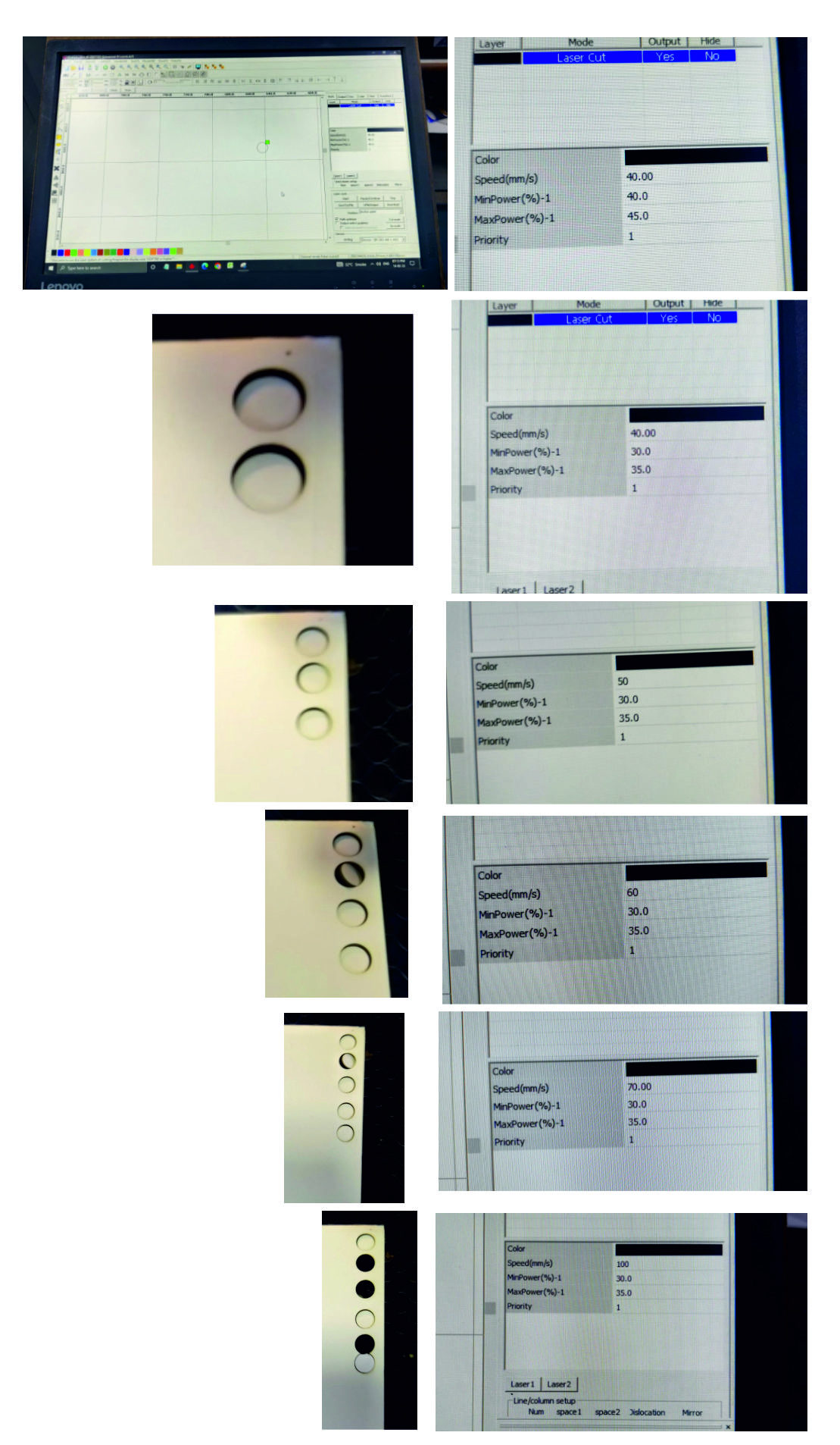
I have had plans to make an actual chart of possibilities with the riidl laser cutter. So we will have sample pcs of different materials say acrylic, mdf, balsa ply, cardboard, paper, leather and stuffs and then with actual samples, create a chart of speed vs power graph. I did not get sufficient time this week with my health issues post travel but will hopefully be making sure to cover this up in coming weeks by putting in extra efforts.
For Kerf,
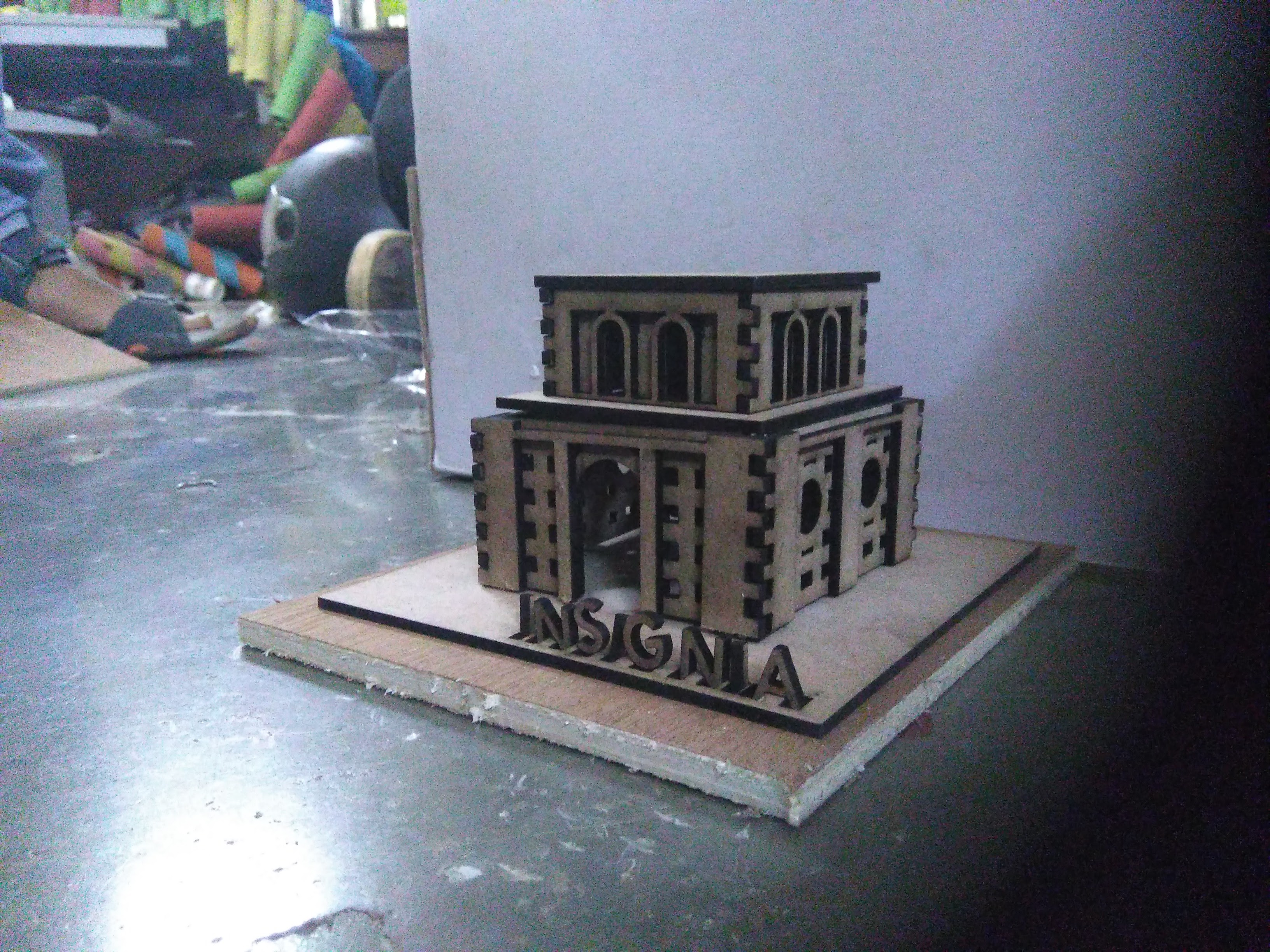
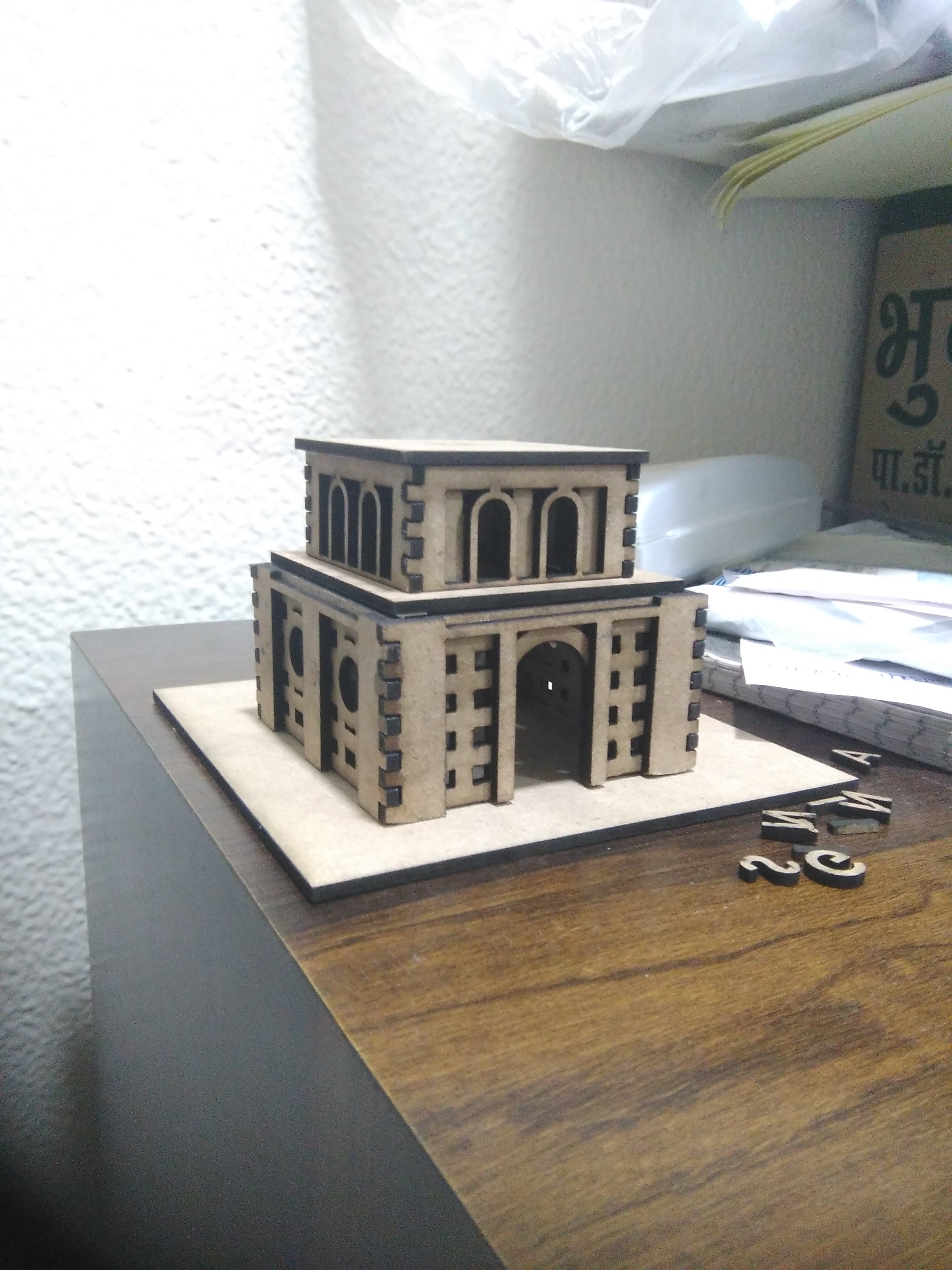
My partner Jesal has already documented this section well, you can refer to his page for details about this grp work: Jesal's documentation So to make some snaps testing, I found my old love, insignia castle that I had built using cardboard in 2017. I decided to make a memory of the insignia castle and build a scaled down version of the same over lasercutter. Here's how it was made for the snapping...
The design was done on coreldraw and the final cut and glued model of the castle looks as shown below:
We also tested with the files linked on the FabAcademy Schedule page Some of the pics are attached below:
Download design files
Castle Insignia file zip - Laser Cut fileParametric dome file zip - Laser Cut file
riidl file zip - Vinyl cut file