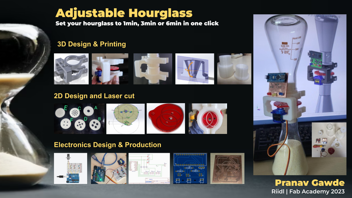
Final Project - "Adjustable Hour Glass"
"Its not about having time, its about making time!" My favourite quote these days, when all that matters is time.
So being from the startup industry and having to review startup pitches almost everyday, the most crucial product I need next to me is a timer. I am super fond of a sand hour glass. I already have one with 1 minute and 5 minute timers. But I always felt the lack of being able to adjust the sand timer to whatever time I would like to set it to. Imagine having a sand hour glass which can range in its functionality from say 1 minute to 1 hour. And we can set that ourselves on the hourglass by some simple buttons! So cool!
Inspiration
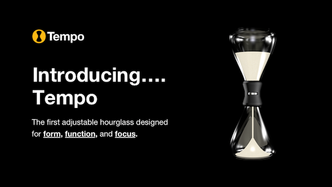
Upon research, yes it does exist in the international market. Here's one shown in the image below from Tempo, but it is adjustable to 3 settings, 5 min, 15mins, 25mins. My plan is to make it more free to adjust. I haven't figured out exactly how but maybe some servo? I don't know, need some time to brainstorm in detail. Coming weeks it will be!
Phase 0: Plan of action
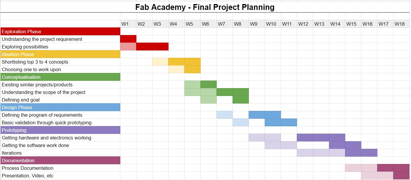
So initially, the first thing is to decide what exactly is needed. In that regards, based on my plans, office work, I made a simple waterfall planning for the final project.The plan is as follows:
Week 1-4 : Finalising the idea to work upon
Week 5-6 : Plan the deliverables, final outcome, start brainstorming and ideating
Week 7-8 : Quick Prototypes and basic validation of the concepts
Week 9-12 : Hands on work with electronics
Week 13-16: Final build, feedback, interations and repeat
Week 17-18: Final prep
A detailed waterfall plan is as shown in the figure below:
Phase 1: Problem Definition
So initially, the first thing is to decide what exactly is needed. Defining the problem statement, program of requirements, scope of the project, etc.Problem Statement: To design and build a adjustable hour glass with 3 possible variations (1min, 3min, 6min)
Program of requirements:
1. The hour glass should be limited to 200 mm x 100 mm x 100 mm as external dimensions
2. The hour glass should have 4 modes of variation at least (1min, 3min, 6min)
3. The hour glass should be leakproof for the sand
4. The electronics should work on replacable batteries
Scope of the project: TRL 3 - Prototype level
What is Technology Readiness Level(TRL)?
Technology Readiness Levels (TRLs) are a method for understanding the technical maturity of a technology during its acquisition phase. TRLs allow engineers to have a consistent datum of reference for understanding technology evolution, regardless of their technical background.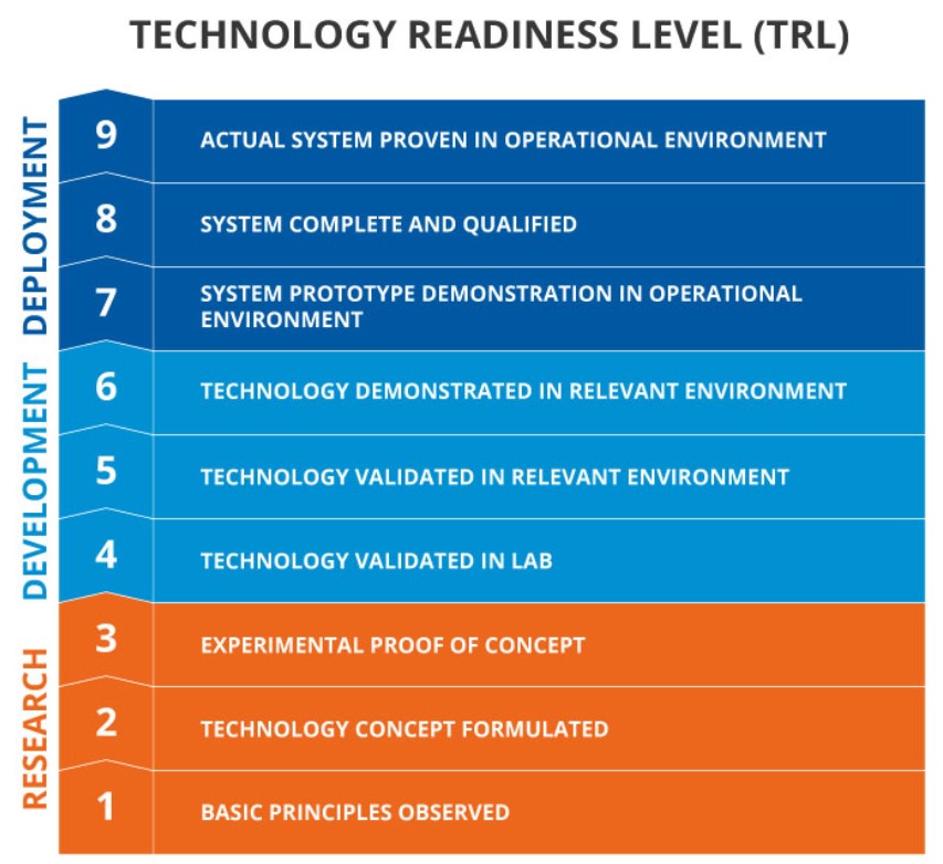
Phase 2: Ideation & Conceptualisation
Initial brainstorming led to few ideas as described below: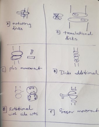
Some of the interesting ideas are explained below:
Idea [A]: There can be disks with different diameter holes in the center of the disks (defining the time it takes for the sand), and these disks can be rotated to be replaced by another over a button actuation using servo.
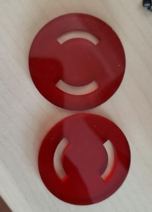
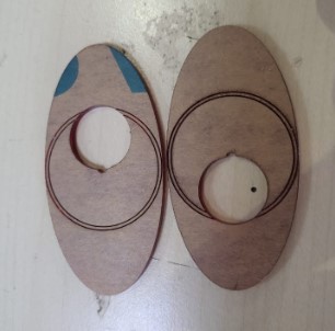
Idea [B]: Instead of multiple disks, there can be translational motion between two oval holed disks and the interection on the holes can define the time it takes for the sand.
Idea [C]: Here I thought, we can have try getting the right combination of slot by using a plus sign at the interaction, but actually it is not feasible as everyting the intersection will be the same sized square or rectangle.
Idea [D]: Maybe we can just have multiple disks one above the other and the holes in it can be such that they can add up to get the right sand time and each disk can be rotated indivitually or interlinked(to reduce servos needed).
Idea [E]: This idea was inspired from idea [C] to some extent but instead of being at the center the interections can happen a bit away from the center and in two locations or more. This will give more easier control ovet the interection tolerance.
Idea [F]: This idea wasa inspired from the spirograph project of ours and it basically means the opening of the center slit by motor controlled movement for the exact amount of sand timing to match.
Further, I focused on 2 ideas to try out and conceptualise a bit more to validate the functionality.
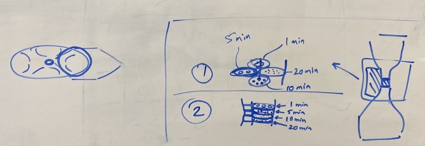
Idea 1 is basically the idea [A], and Idea 2 is basically the idea [D], but in both the cases the definition of the center hole diameter for exact sand to pass through for a specific time stamp is very important. So the first ideal iteration would be to figure out the dimension of the center hole diameter by trying out various versions of the same.
Iteration 1.0
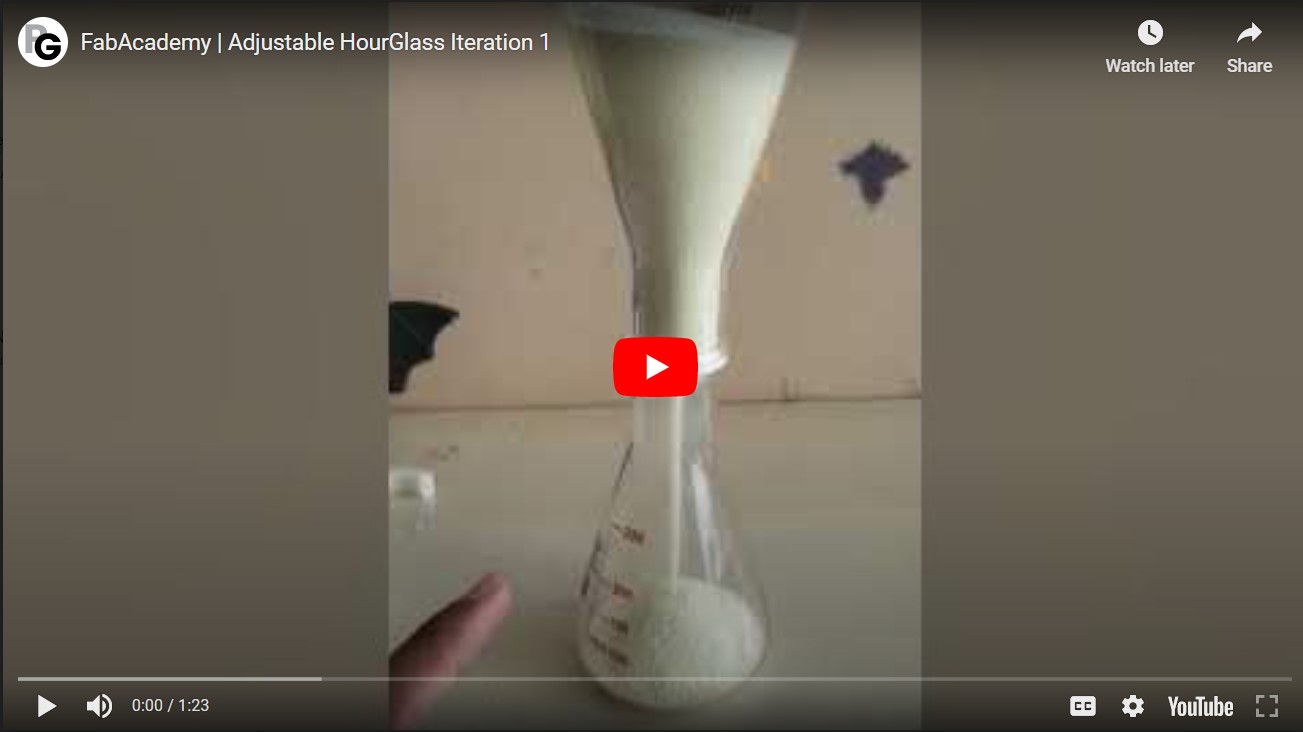
So as first iteration of the hour glass project, I decided to achieve the bare minimum requirements in terms of functionality of an hour glass. So the aim of this iteration was to figure out the basic hour glass working. And possibly figure out the magic diameters for the hole openings between two sides of the hour glass to get exactly the 1min, 3min, and 6min time slot. Also to fix the overall size of the hourglass I would need that again depends on the amount of Sand I would need based on the leasst possible diameter I can go without having inefficient transfer of sand.Iteration 1 working video
Disc Concepts test
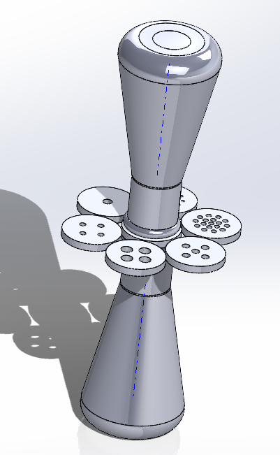
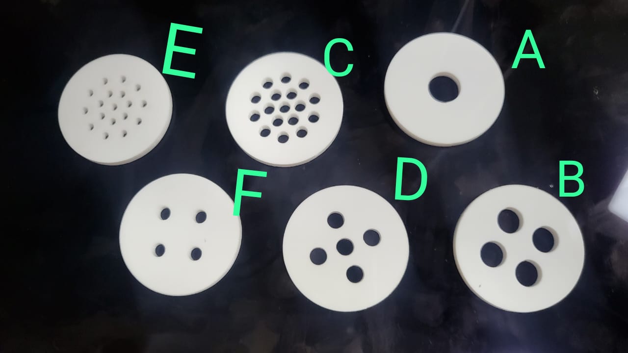
I explored the holes in the disks to be defined so that the timespan is exactly 1 min, 3 min, 6 min. The shapes were designed on Solidworks using just intuitions and trial and error in the initial stage. To design the disks, first the The disks were cut on a spare acrylic sheet (4mm thickness) on the laser cutter at the FabLab in riidl.The solidworks files and the laser cut disks are shown below:
I also tried the other brainstormed ideas to test out but they didn't function well as it wasa very difficult to adjust and find the right movement of the disks in sync with each other.
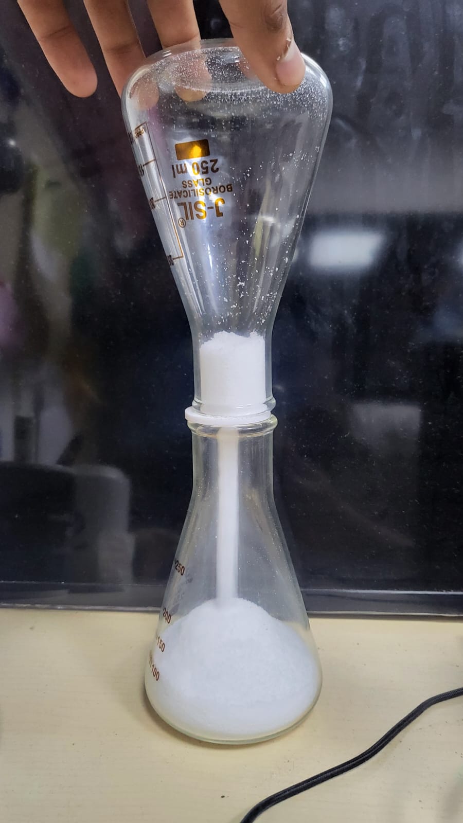
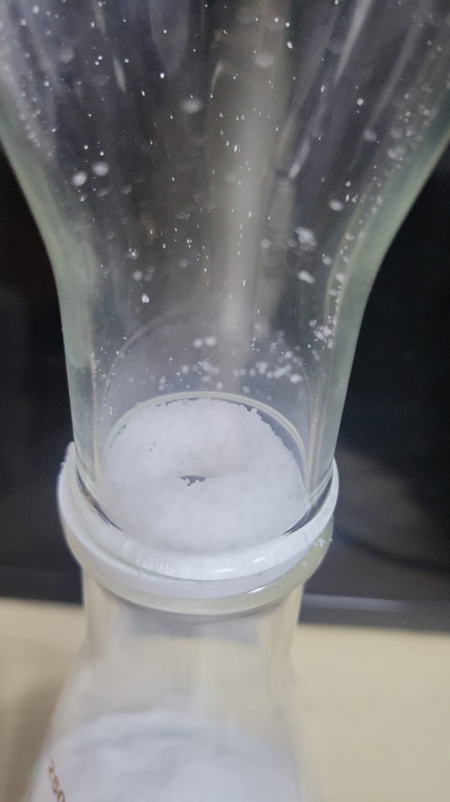
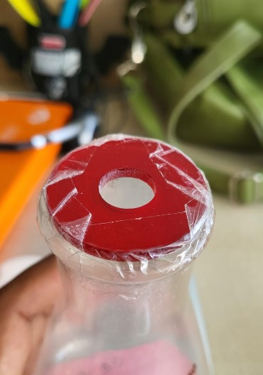
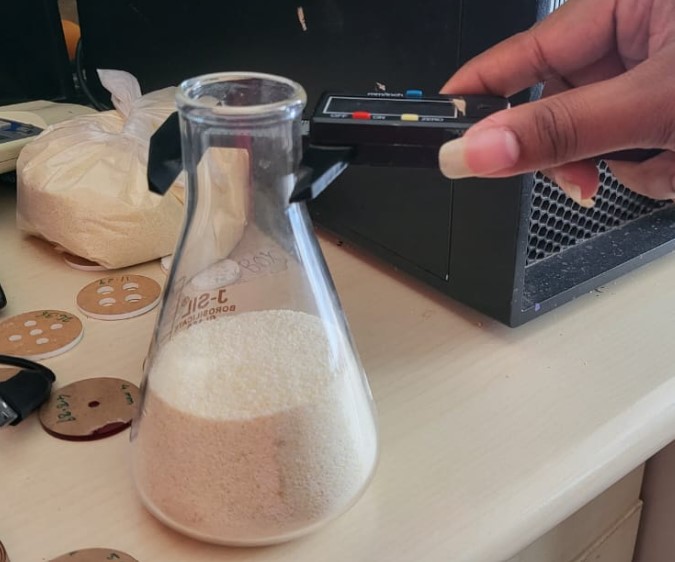
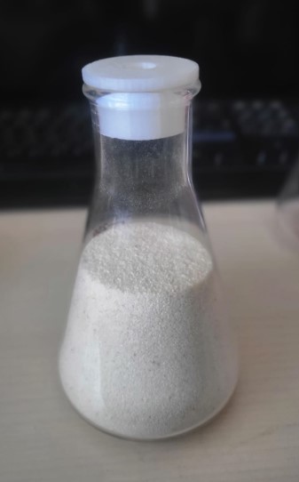
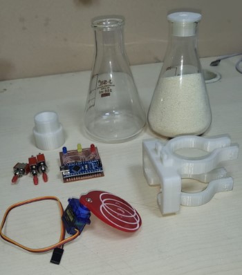
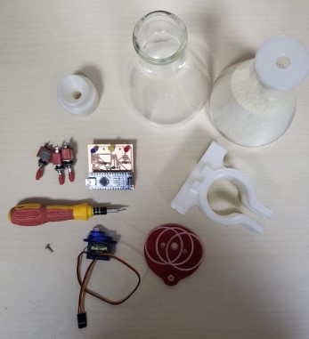
To try out quick tests with these disks, I decided to use a DIY setup. So, I used 2 concical flasks from our Biolab as top and bottom containers for the hour glass And I did one mistake of not using the right material that is the sand. I being lazy, first tried to used Salt as it was locally available to me without having to put efforts. But since salt had moisture, it backfired. The tests failed as it was sticking to the disk and blocking the holes, instead of flowing smoothly. The test setup and the failure is shown in the figures below:
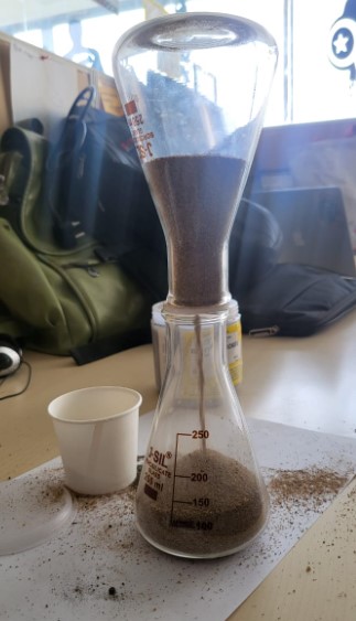
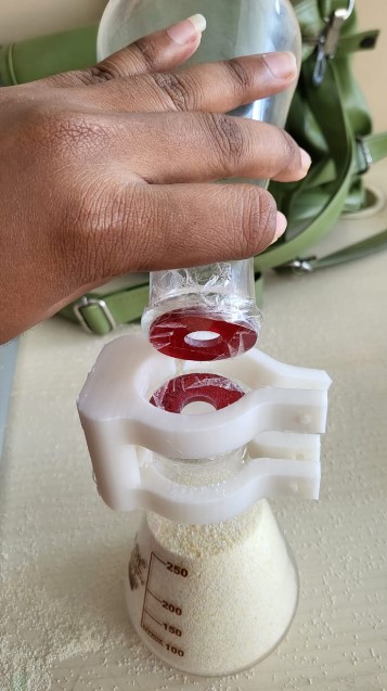
Finally, I borrowed proper sand from a construction site. First refined it and finally tested out my disks. The new test setup is shown below:
The outcomes of the test are as follows:
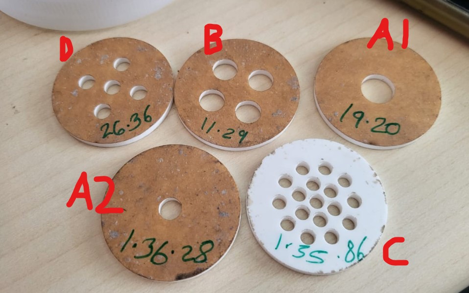
So I measured the time taken for the sand to pass through each of these disks. The numbers written on the disks in the image above is the time that respective disk took. Not only the time measurement but this experiment also helped me check on which pattern is efficient and which is not. Especially the consistancy of the flow was found to be differing in different patterns. The analysis of the same is mentioned below for each of the disk.
1. Disk A:
Disk A was the most successful one compared to others as it was consistent throughout the flow. The sand passed through the hole without any change of volume flow every second and that will help me get repeatability in my design. Also I then quickly cut another same pattern disk to check the consistency and change of time taken dependig on the diameter of the inner hole. Both A1 and A2 discs worked efficiently. A1(8mm diameter) took 19.2 secs while A2(6mm diameter) took 96.28 secs. Thus demonstrating how much a 2mm change in diameter can effect.
2. Disk B:
Disc B was equivalent to 4x times the A2 hole, so ideally I estimated it to take 96.28/4= 24.07 secs approx. But it ended up being super fast than expected. 11.29 secs. Initially I couldn't figure out the reasoning, but then I realised it is obvious that it won't be linear.
3. Disk C:
Disc C took 95.86 secs, alomst similar to the A2 disc. But A2 is a repeatable result, Disc C wasn't. The reason being that the disc C has smaller holes and sometimes couple of holes get blocked somehow and stop the sand flow through them. Thus proving it a bit unreliable.
4. Disk D:
Disc D took 26.36 seconds again similar result like Disc B. Also making it evident that the change in number of holes has less impact in the sand movement than the change in diameter of even a single hole.
5. Disk E & F:
The discs didn't let the sand flow through it that fluently and thus are just out of the picture to even consider.
Based on the above observations, I again laser cut more discs with just single holes in the center with changing diameters ranging from 2mm to 6mm.
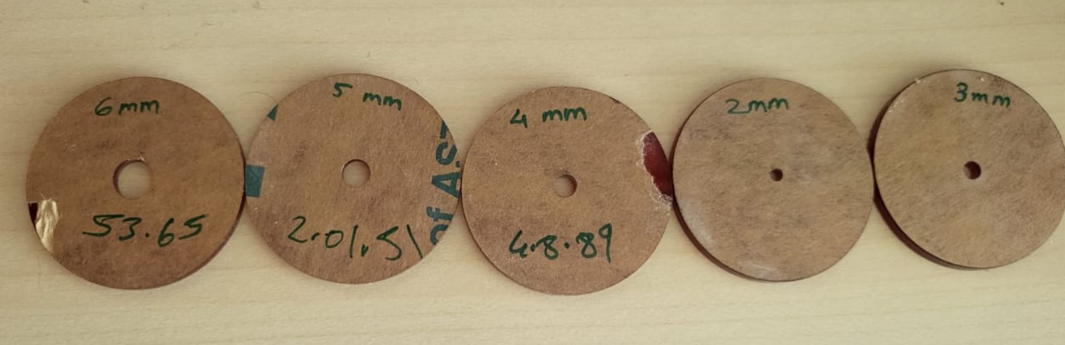
That helped me understand the timings I need to have with what diameters approximately. I also increased the sand in the flask to 250ml mark (previously it was 200ml mark). This gave me a bigger window to get a more accurate design for 6 min timer as the current diameter was coming around 3mm or lower and that was a bit difficult to maintain due to the sand grains size in my sand collection. So now I got new readings for the 1 min, 3 min and 6 min pitch timings and then based on them I made few more repeatitive tests.
The tabular representation of all the tests above is presented below for reference:
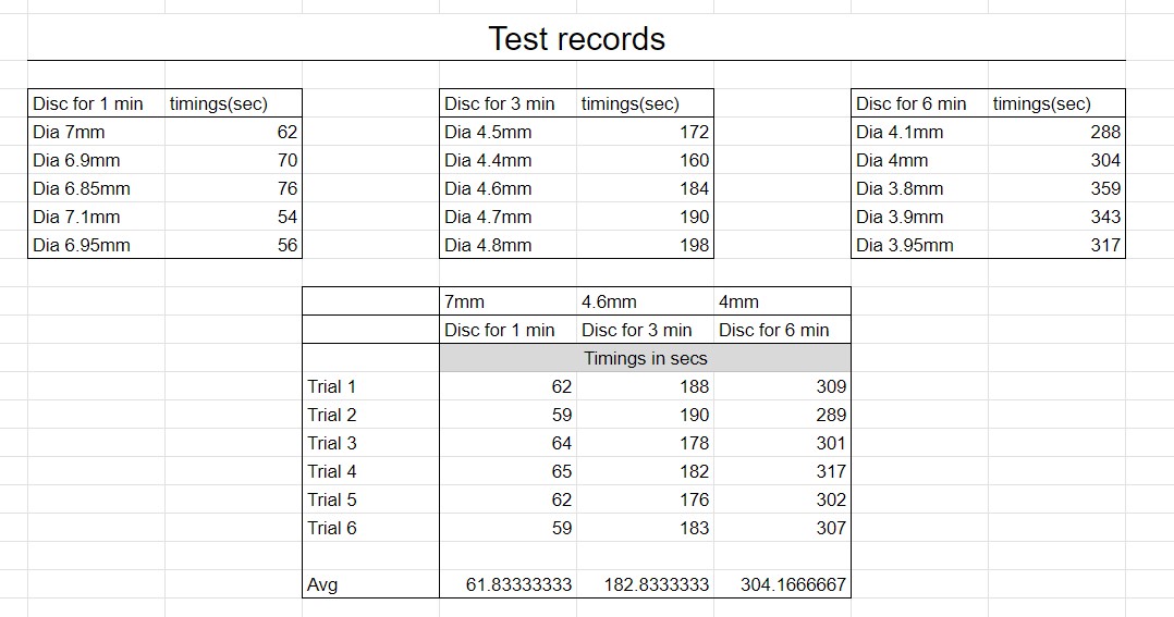
Final outcome of the tests
Then I reiterated with few more adjustments to the discs to get exactly the right diameter hole I would need for a 1min, 3min and 6min hour glass.Those came out to be the following combinations:
1. For 1 min pitch : 7 mm diameter for 1 min Averaged(Tested with 6 repeatations)
2. For 3 min pitch : 4.6 mm diameter for 3 min Averaged(Tested with 6 repeatations)
3. For 6 min pitch : 4 mm diameter for 6 min Averaged(Tested with 6 repeatations)
Phase 3: Designing the hardware
After having a clear understanding of the disk designs, the first step was to list down the things needed.List of mechanical design constraints needed:
1. Holding the flasks over eachother2. Holding the disk at it's place (i.e. between the two flasks)
3. Making sure there is no gap between the two flasks so as to not let the sand leak.
4. Mechanism for the disks to rotate (most likely servo motor)
5. Mounting of the disks over the servo
6. Mounting of the servo motor in the casing
List of Electronics needed:
7. Servo motor or Stepper motor and driver8. Microcontroller to automate the servo movement
9. Input devices - button to switch between 3 modes
10. Output devices - LEDs to indicate which mode it is
List of Aesthetic, Ergonomic and User friendly design requirements:
11. The outer body i.e. the casing of these above mentioned components12. Balance the weight of the hour glass throughout.
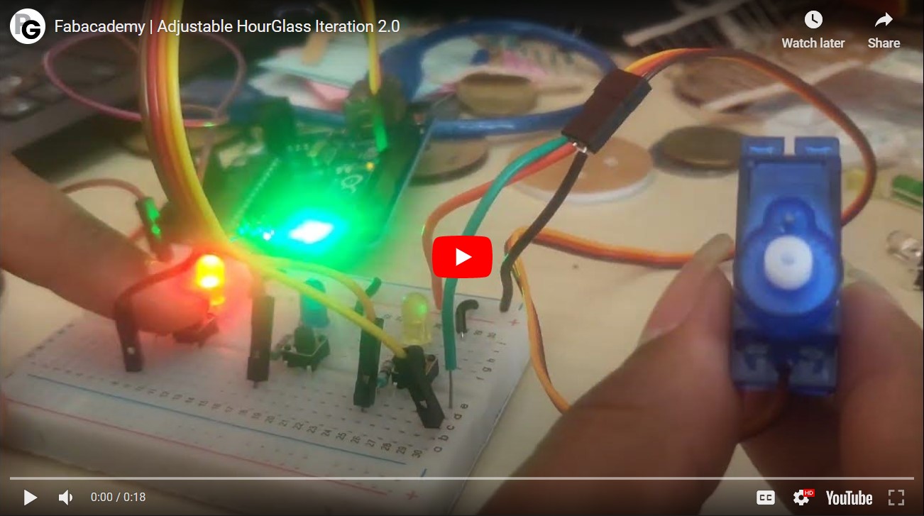
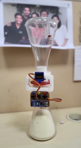
Iteration 2.0
For Iteration 2.0, the next step was to design the holding, body, disk orientation, electronics to be used, and also a way to hold the two flasks together in the prototype model.Iteration 2 working video
Hardware: Mechanical
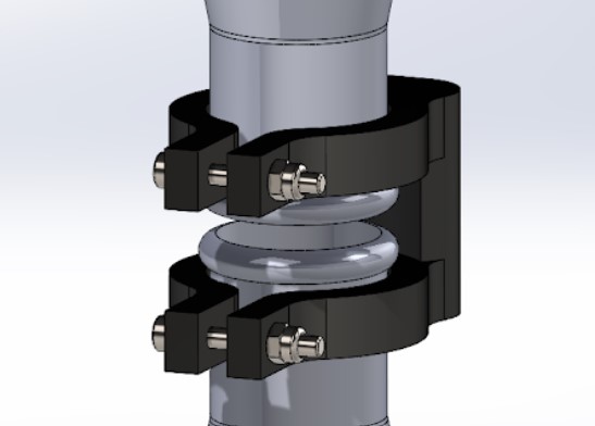
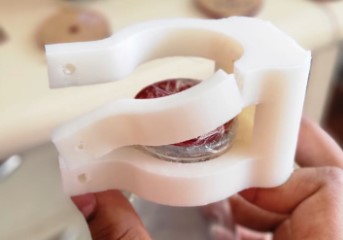
Holder for the 2 flasks:First of all, I fixed an acrylic plate on both the flasks with the central holes of 12mm so that the flasks are easier to handle.
For the current state to test, I designed the holder on solidworks by measuring the outer diameter of the flask and then made an adjustable design using a 4mm bolt and nut to tighten as shown below:
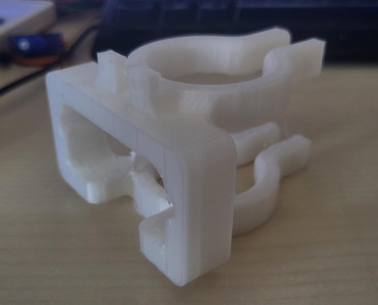
The design was 3D printed and the test looks as shown below:

In the above design multiple things were noticed to be solved in this Iteration 3.0
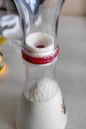
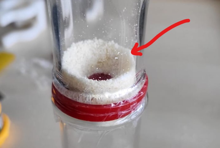
1. Sand leftover in the top flask:
So everytime the timer was set, since the flask tip is wide and not that narrow as it ideally should be, also since the disc is flat, there were lot of sand residue that was left on the disk and thus resulting into inefficient reading every time.
2. The holder printing direction:
The holder I printed above was a bit weak and broke after 5 to 6 in and out actions of the flask. So that's when I realised that even after having a good width of the holder arms, it breaks - meaning into weaker building. Maybe I need to print it in a different orientation and try again.
Hardware - Electronics
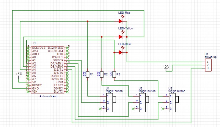
The electronics is the most important part here if I want the hour glass to work the way it is supposed to be. SO the electronics has following elements:1. Decision Maker - Arduino Uno or Arduino Nano
2. Input Devices - DPST buttons/switches
3. Output Devices - LEDs
4. Actuators - Servo motor
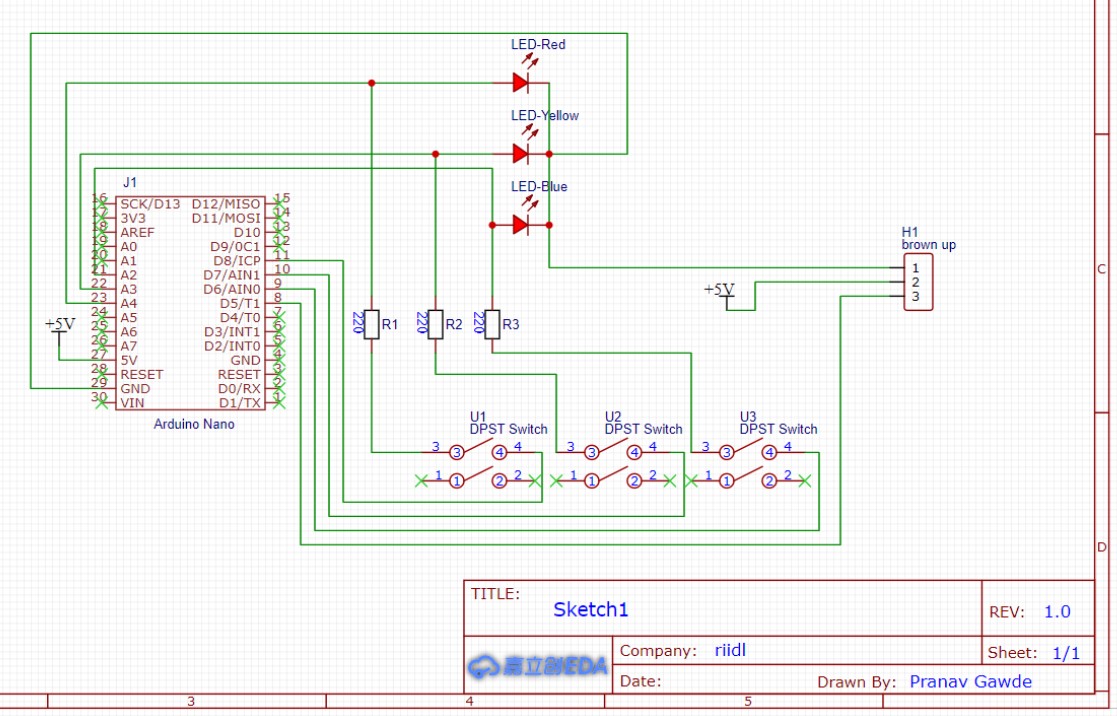
The circuit diagram design looks like the one I tried on TinkerCAD
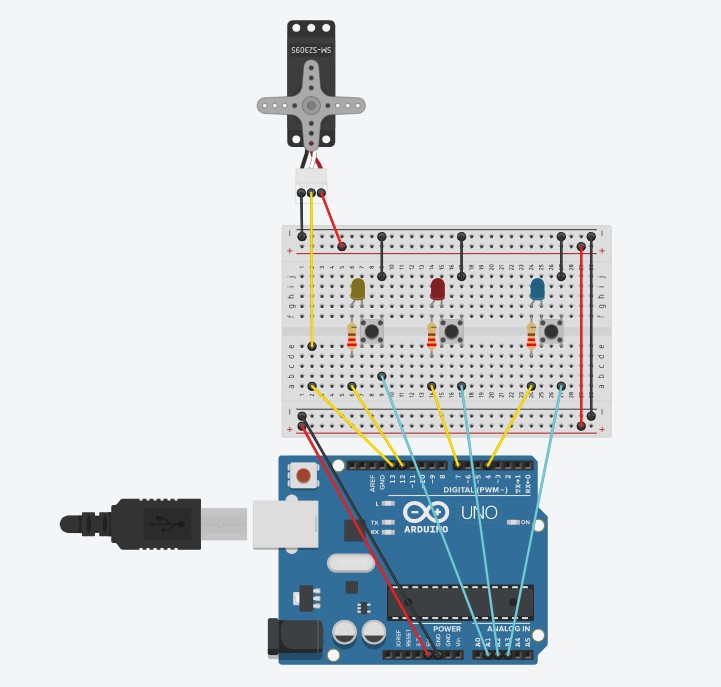
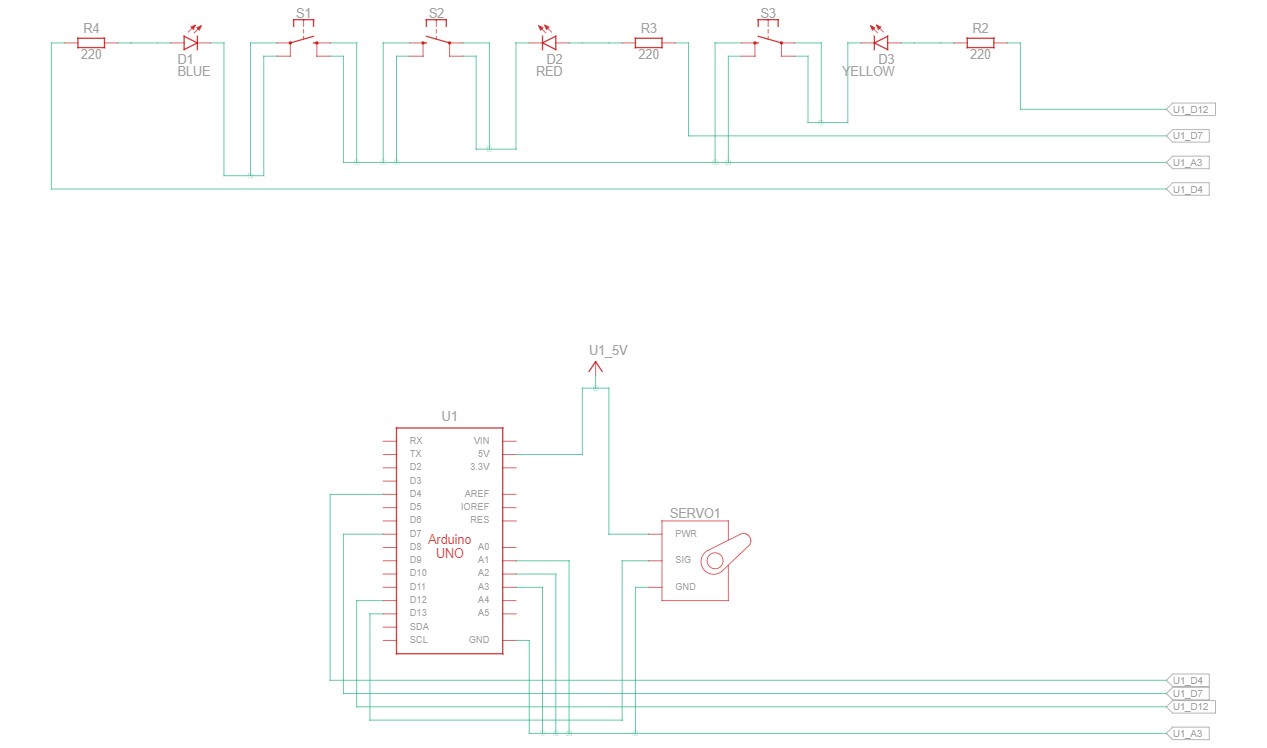
The electronics prototyped on a breadboard in reality is shown below:
Note: Only few wiring is changed. The digital pins are shuffled.
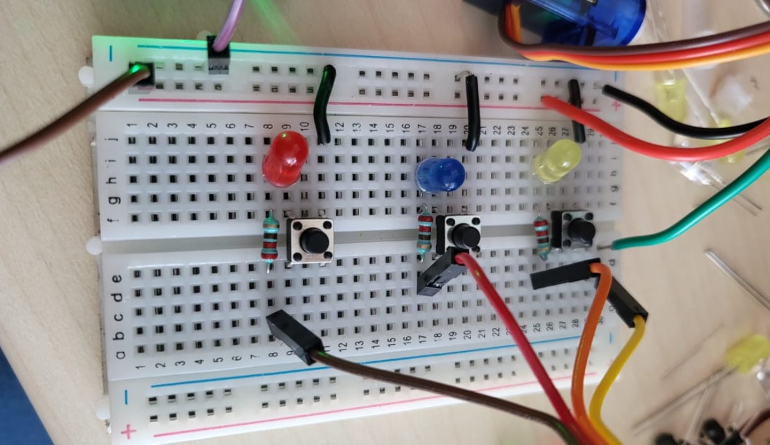
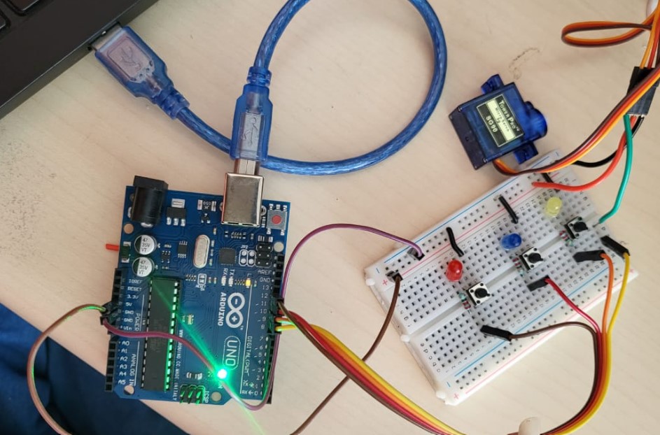
The electronics is rightly wired and connected, only few modifications:
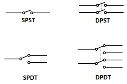
1. The switches used in the above were DPST switches, but momentary switches. We need latching or toggling switches and can be either SPST, SPDT, DPST or DPDT - that is manageable.
Momentary v/s Latching switches
A Momentary push button function means that when pressed down, it immediately returns to its natural state. For it to either change the function, it’s required to be touched or pressed.
A latching push button function also referred to as maintained, means that it remains in a position until pressed again. It required to be pressed down or touched multiple times to either turn on or off the device or function. It aims to push to make and push to break a cycle and can also be referred to as normally closed push switches.
What are SPST, SPDT, DPST, DPDT switches?
SPST means Simgle Pole Single Throw and SPDT means Single pole Double throw and similarly others. What is pole? and What is throw? These questions can be answered better by understanding the image below:
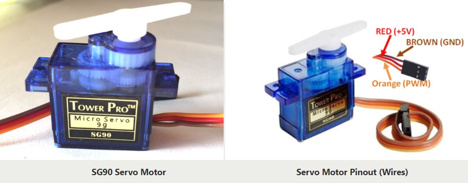
2. The servo turning angle needs to be defined to use it efficiently. The wiring of the servo is also important as shown below:
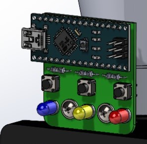
3. The arduiono board can also be replaced with Nano board as we don't need much pinouts in our case and the Nano can be easily mounted on a PCB.
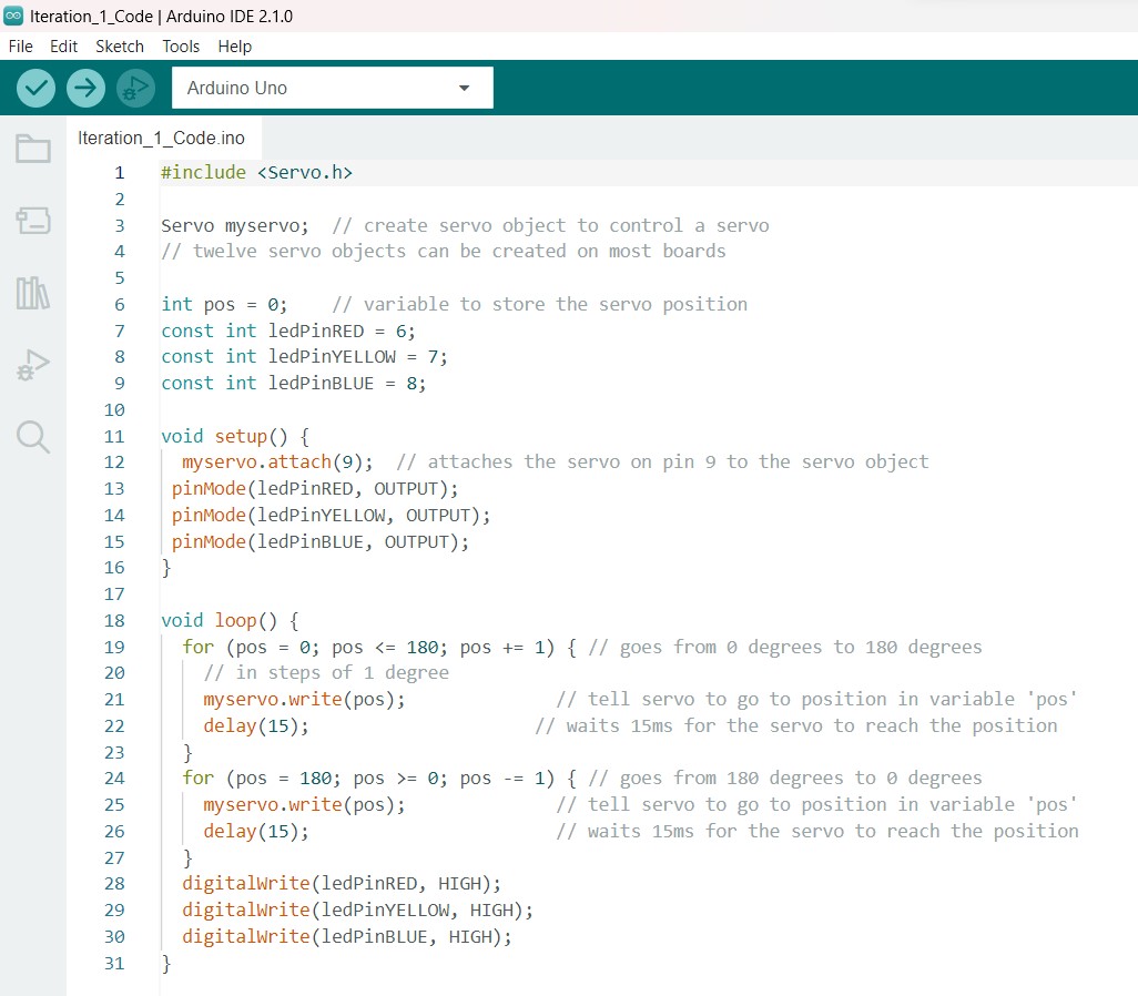
Software
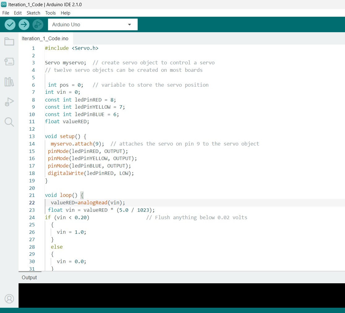
So for the coding part, I am working on Arduino IDE. So the basics of using the Arduino IDE platform was already covered in Week 4, and even Week 8. The new thing I had to do was to include Servo library.The code used for the breadboard circuit test is shown below:
Iteration 3.0
Iteration 3.0 included the complete body and mounting of all parts on the holder itself for the 2 flasks in terms of hardware and it included designing a pcb and soldering and testing the same.Iteration 3 working video
Hardware improvements
Designing the tapering blocker of the flask
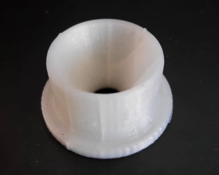
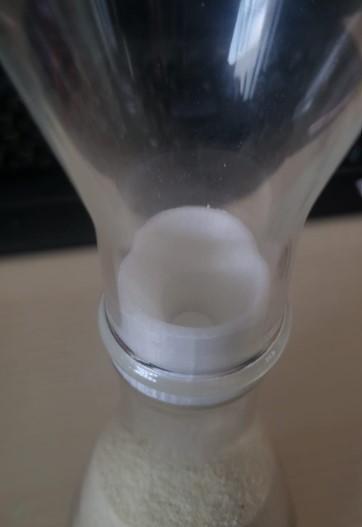
As discovered in the previous version that there was sand residue in the flasks as the blocker was a flat laser cut disc, this time I designed a 3D printed tapering blocker. The design was made by calculating the inner diameters of the flask. The design was made to be press fit so it stays in position and doesn't need any type of adhesion.
The part was printed and tested with the flasks as shown below. Now it functions without any sand residues.
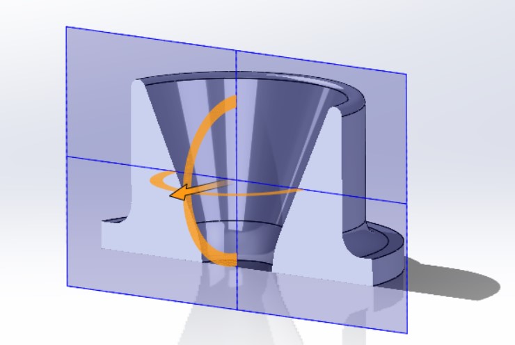
Designing the disc and servo mechanism
In the last iterations, we figured out the exact diameters of the holes we need for 1 min, 3min and 6min timings. Now we need to design the mechanism that will work to quickly shift. As per the initial plan, the servo movement will help us shift the holes from one to another. But there are some constraints and requirements as listed below:
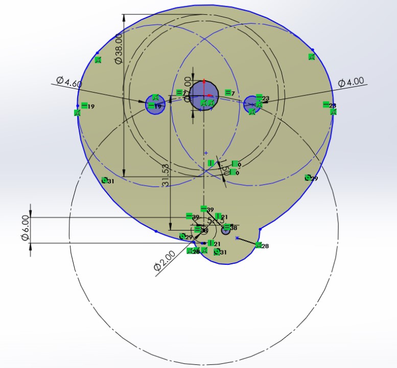
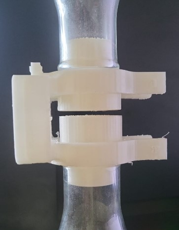
Designing the holder v2.0
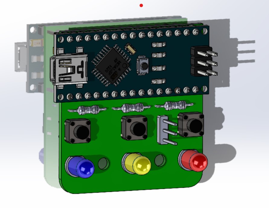
Next step up is redesigning the holder. Also the holder now is suppossed to have a mounting for the PCB, the servomotor, the rotating disk and ofcourse the flask with the blocker. Before designing the holder, I had to source the CAD files or make the CAD files for the parts to be mounted that is the servo, and the PCB. The PCB was designed based on the dimensions obtained from the design in EasyEDA(see electronics section below). The components on the PCB were fetched from GrabCAD Library and servo was also fetched from the same place.
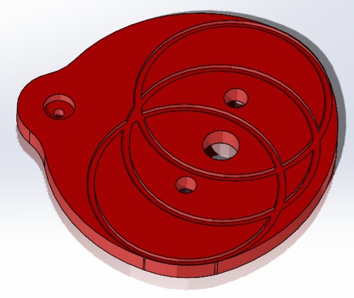
These components were assembled in the Solidworks assembly files and based on these mates and dimensions the new holder was designed as shown below:
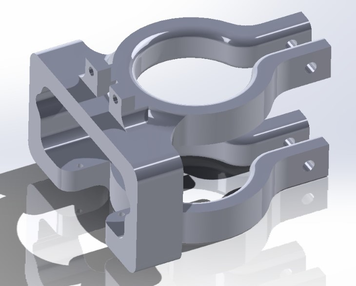
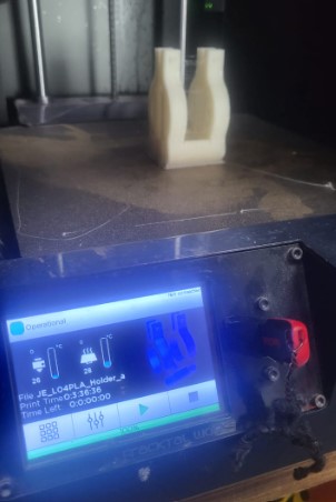
The holder was weak in layers as the 3D printing gcode was sliced in a different orientation. So changed the orientation as shown below.
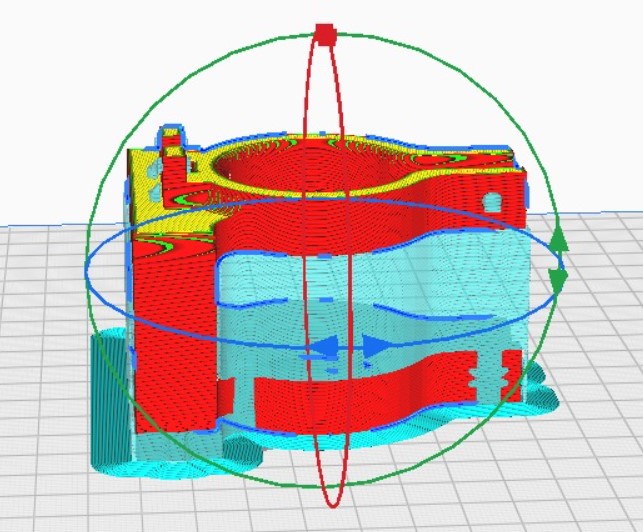
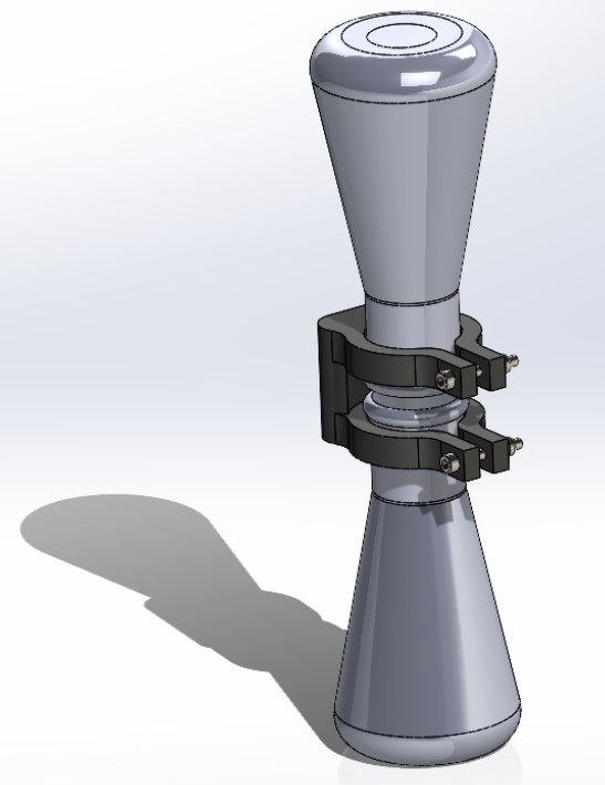
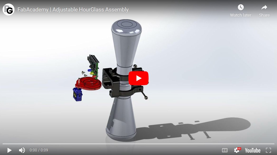
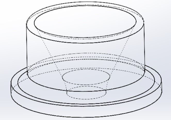
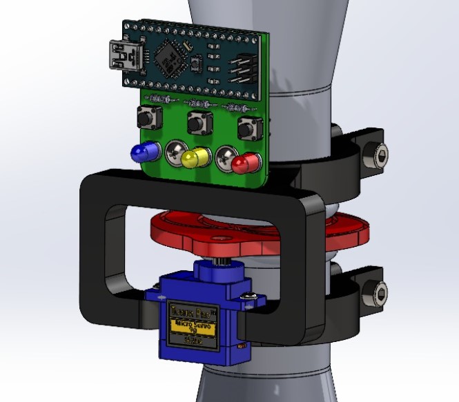
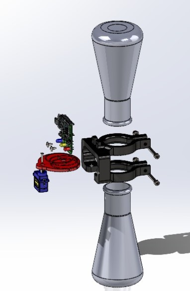
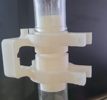
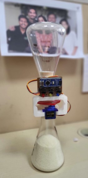
Assembly
The assembly design as seen in the image above was also designed in Solidworks and then all the parts were arranged and assembled step by step as shown below:
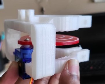
The servo and the disk is assembled as shown below.
During the assembly, it was realised that the holder needs to be of a specific size (atleast 20mm apart) but on the other hand, the space between the flasks need to just equal to the thickness of the acrylis disk on the servo motor. The disk on the servo motor needs to be as light weight as possible. So I chose the 4mm thick disk for that so I need to compensate for 16mm somewhere else. That led to a change in the blocker design. I compensated the 16mm here with the blocker. The new blocker looks like shown below:
Note: Both the blockers are different in size by few millimeters as the servo axes are not centered as discussed below.
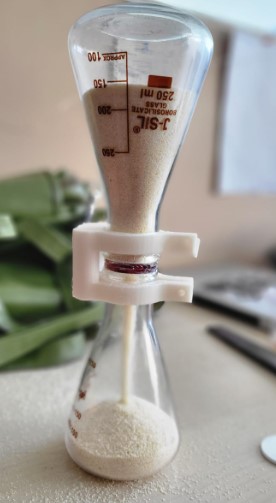
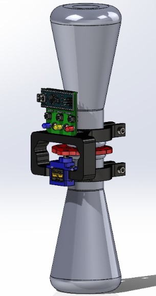
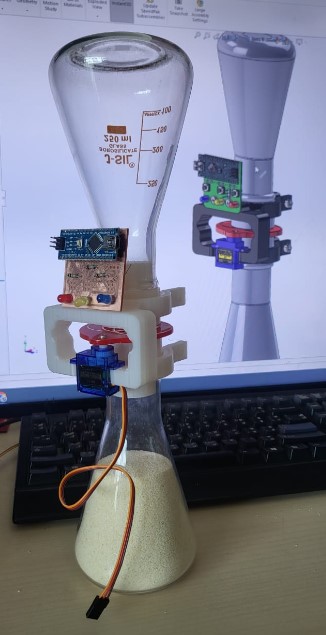
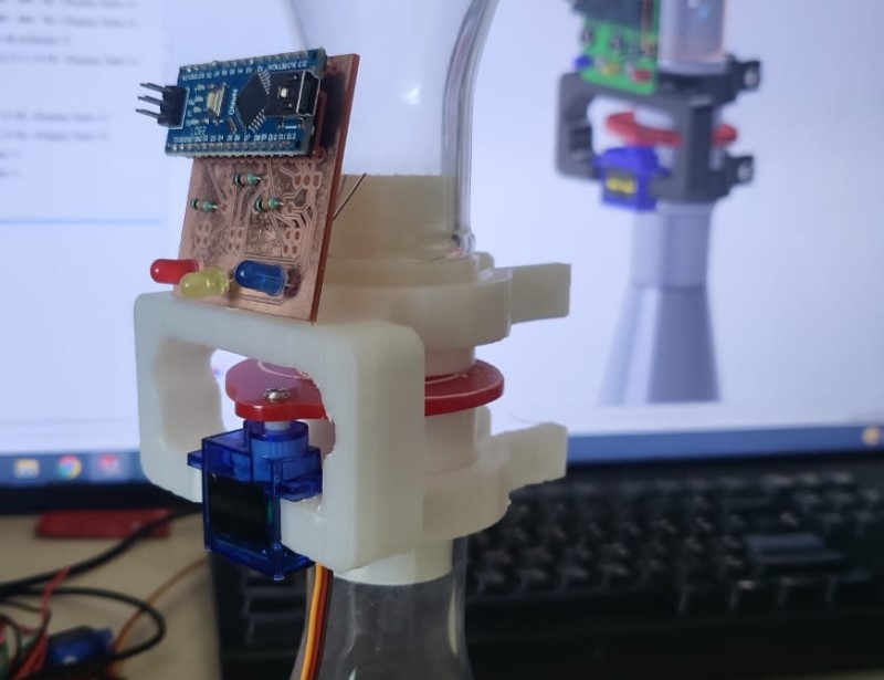
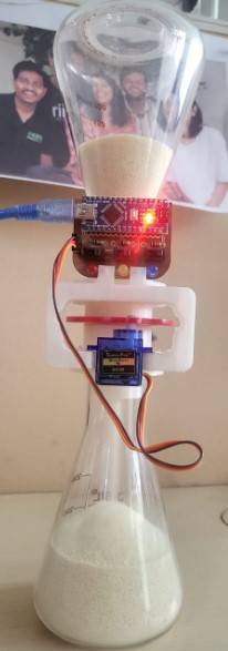
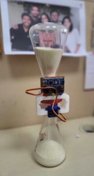
The electronics PCB assembly and its improvements are explained in the section below. But meanwhile, heres how it's mounted. The complete assembly looks as shown below:
Heroshot
Electronics PCB Design
The electronics we need is mentioned below:To hold that together, I started first assembling the electronics on Solidworks over a PCB. You can either design the electronic components by measuring using vernier caliper or just download CAD files online from the universal contributors on GRABCAD. The setup looks like the image below:
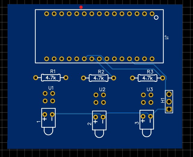
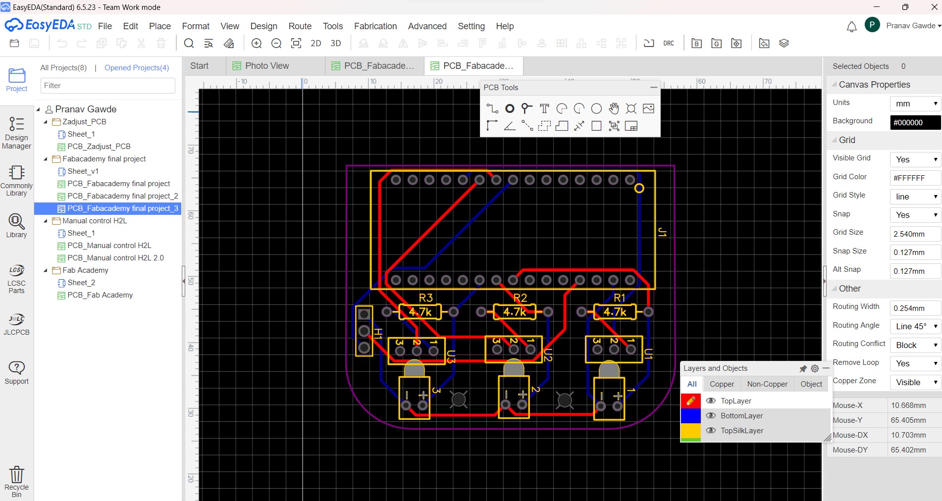
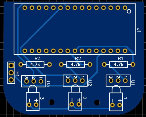
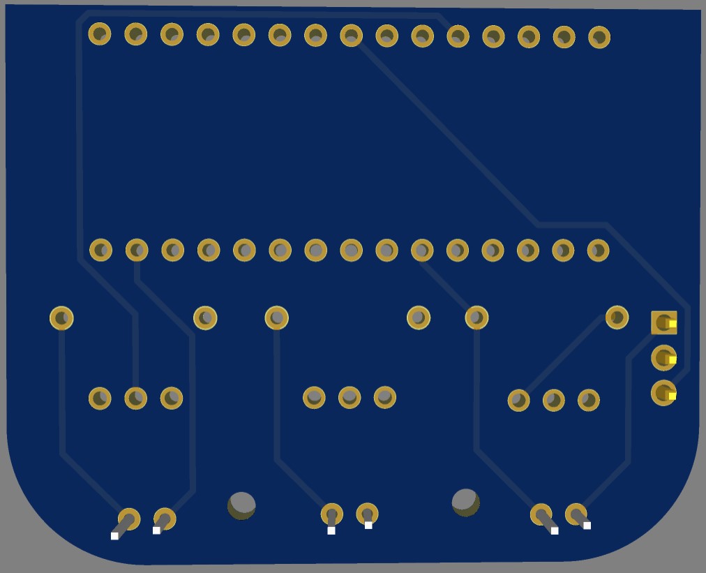
The PCB was designed on EasyEDA as shown below:
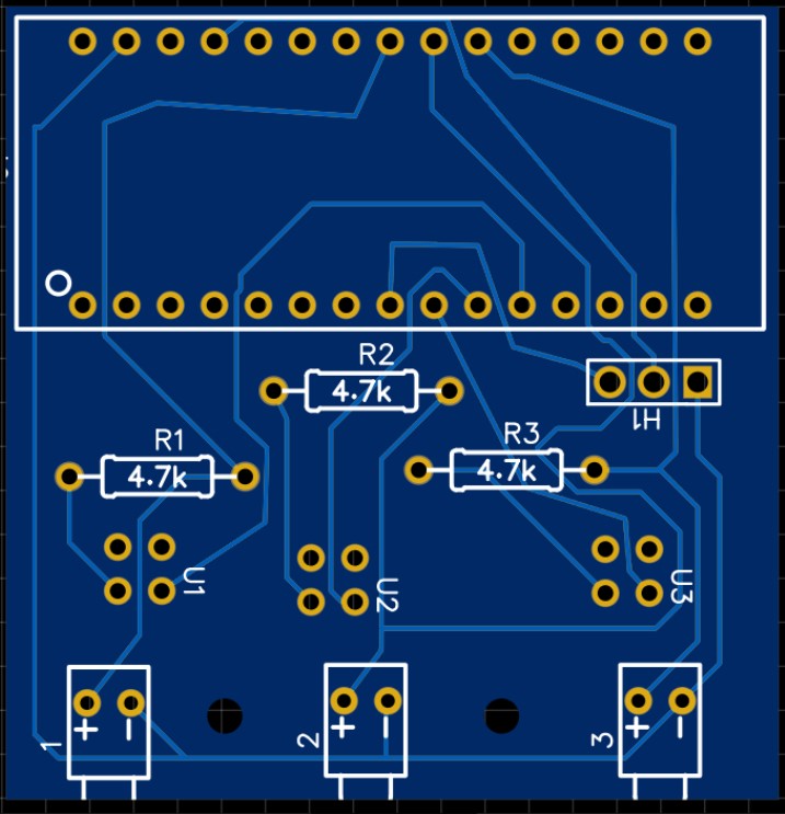
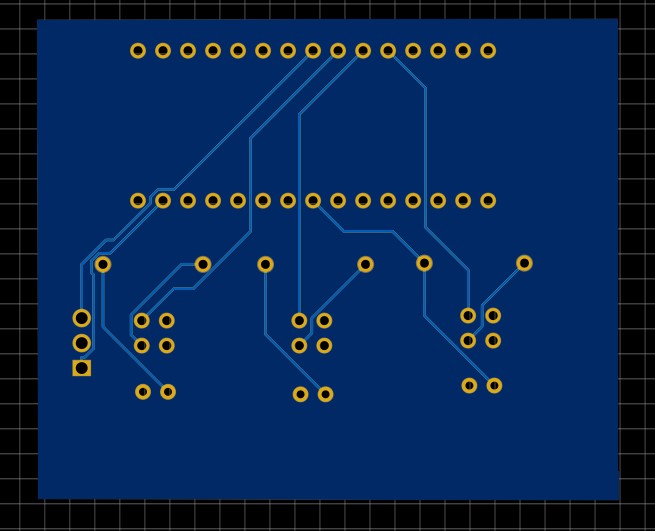
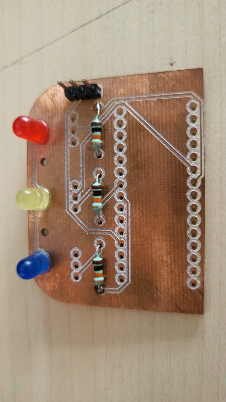
The design was deliberately made with one sided copper layer for quick testing. But it actually becomes very difficult to solder components if the components are not SMD and the PCB is only one side copper. So actaually not a good choice to opt unless you designthe whole PCB upside down. The ideal way to do it is to have 2 sided PCB design as shown below:
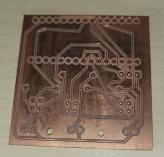
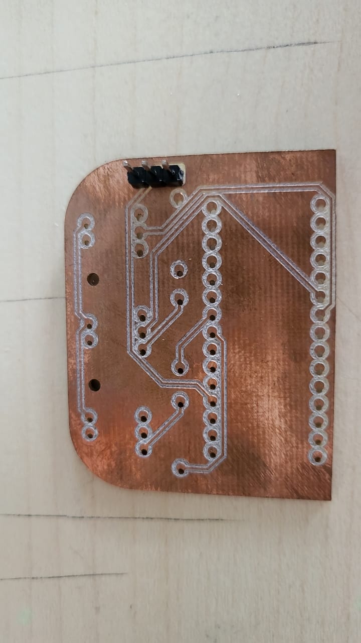
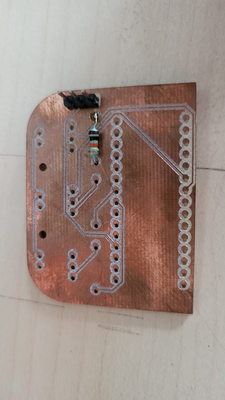
The PCB fabrication was done on Protomat E44 milling machine.
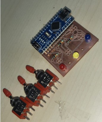
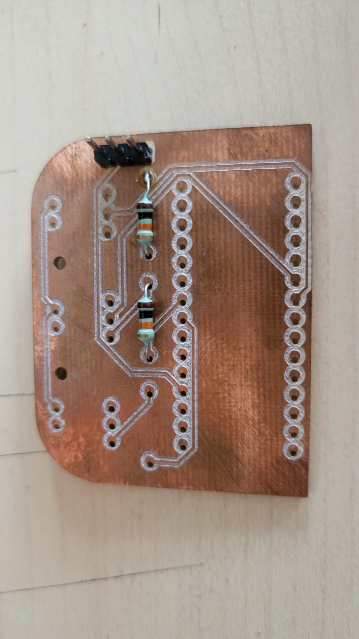
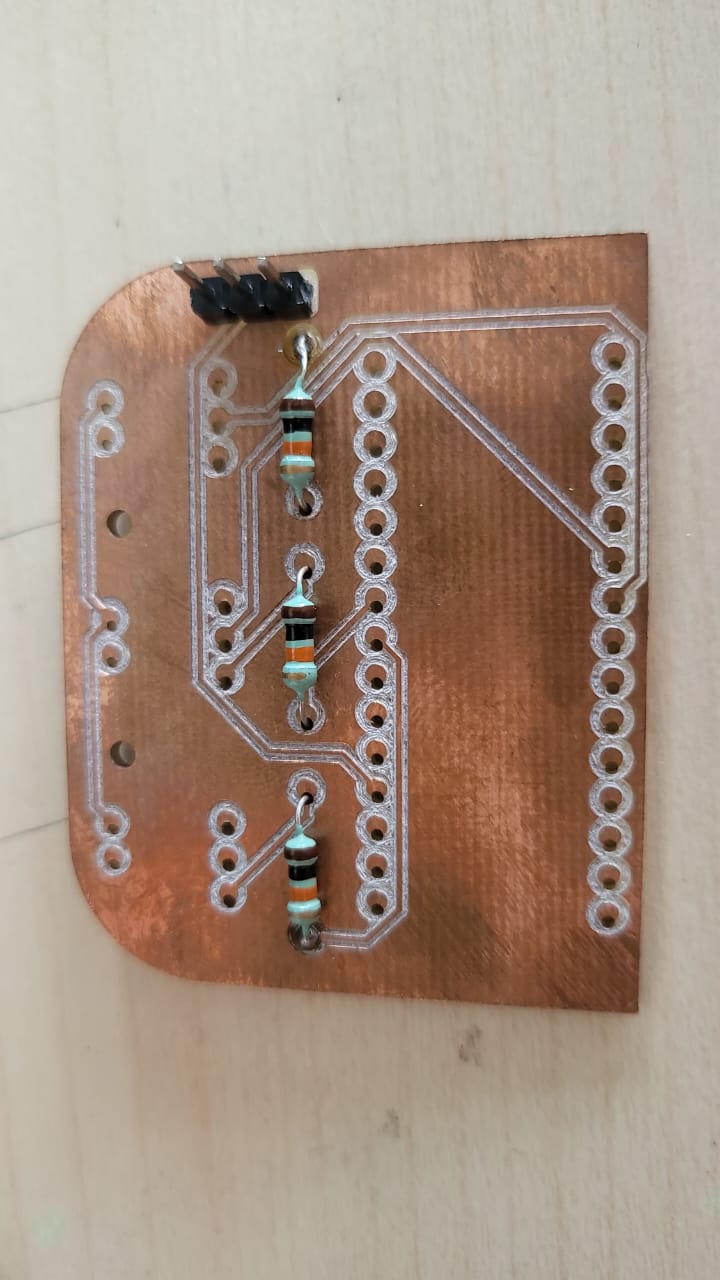
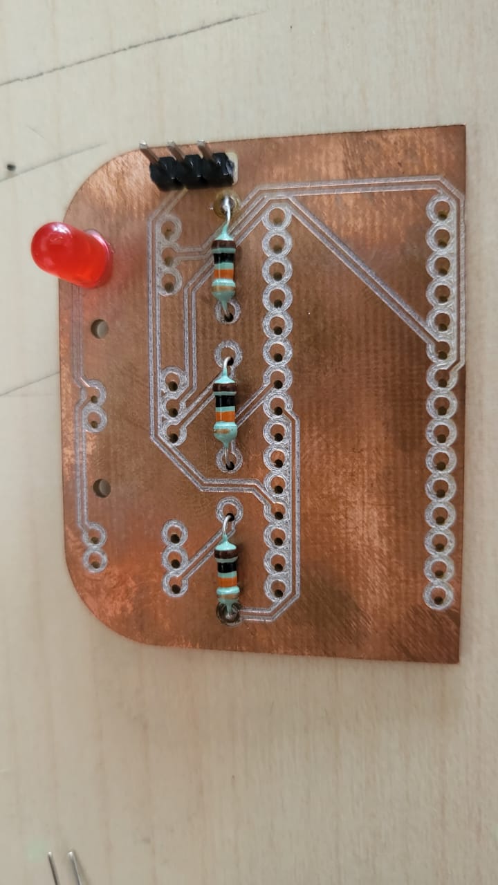
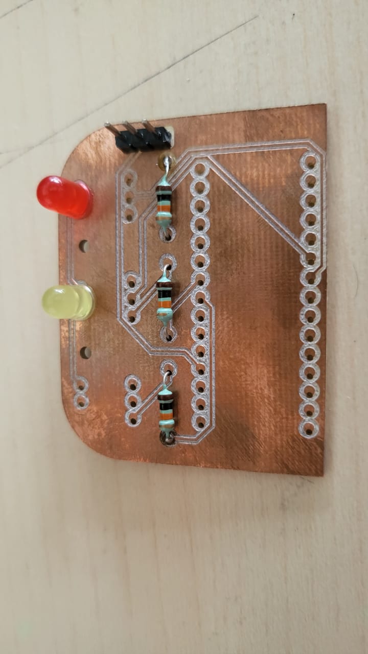
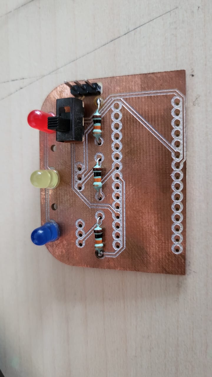
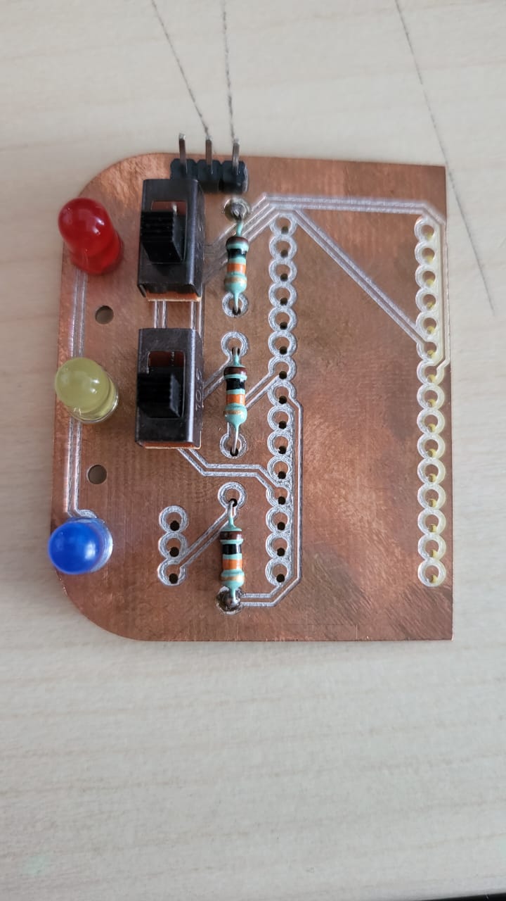
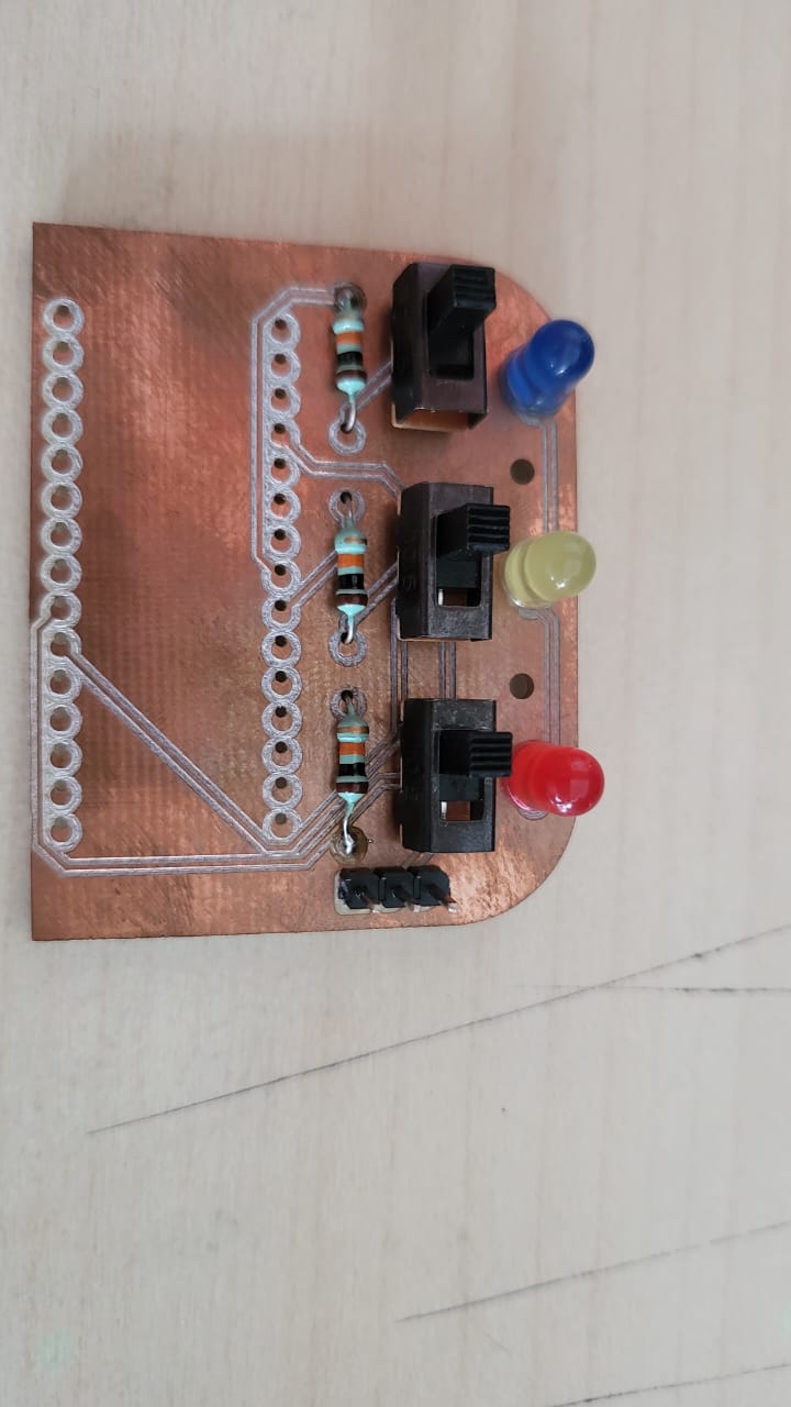
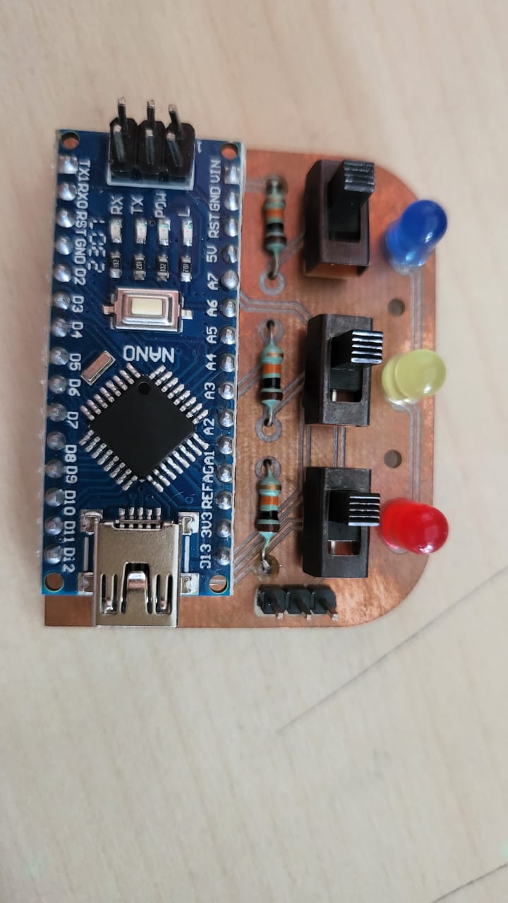
Then all the components listed above were mounted on the PCB and soldered. I could not find proper latching switches I was looking for, but instead settled for toggle switches(SPDT) as shown below. These toggle switches were wired from the copper pads for the actual switches in the PCB design using single stranded wires sooldered at both ends.
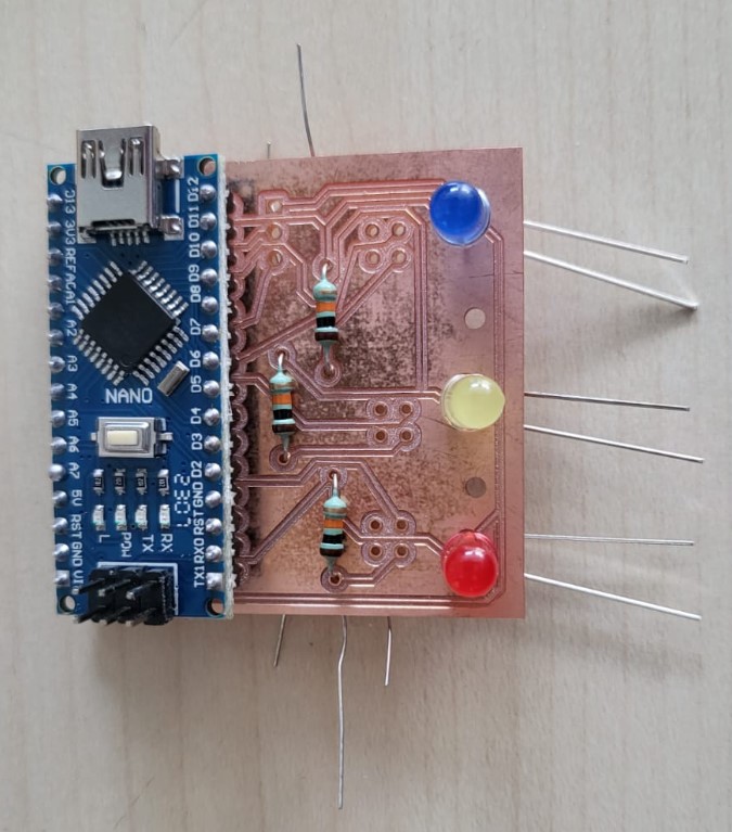
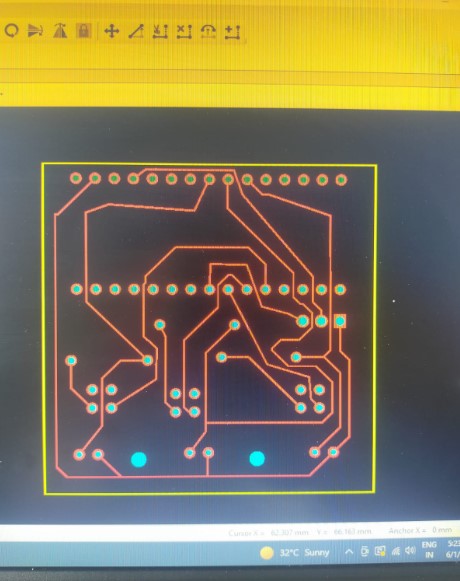
After Neil's review, I decided to redo the PCB with proper toggle switches, so here's the PCB design Schematic of the new version:
The soldering process of components can be visualised in the images below:
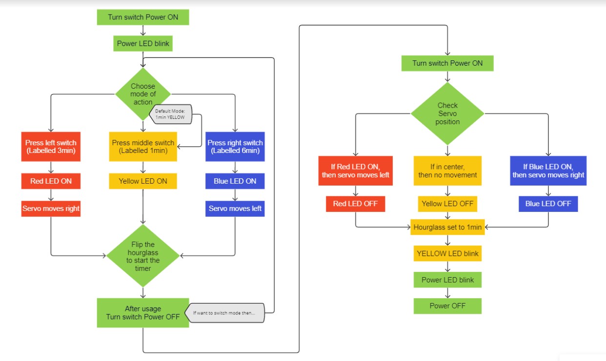
Software: Not it was time to design the code in a much better format with all the ifs and buts and in the order of actions. So for the same, it was necessary to first make a flowchart that explains the flow of action. Based on this flowchart, the code can be written for the next iteration. The flowchart planned for the circuit to work is explained in the image below:
Based on above flowchart, here's the code I wrote for the testing with arduino uno and the above listed components.
          #include <Servo.h>

            Servo myservo;

            int pos = 0;
            int vred = 0;
            int vyellow = 0;
            int vblue = 0;
            int power = 0;
            const int ledPinPower = 9;
            const int ledPinRed = 8;
            const int ledPinYellow = 7;
            const int ledPinBlue = 6;
            float valueRed;
            float valueYellow;
            float valueBlue;
            float valuePower;

            void setup() {
              myservo.attach(5);
             pinMode(ledPinRed, OUTPUT);
             pinMode(ledPinYellow, OUTPUT);
             pinMode(ledPinBlue, OUTPUT);
             digitalWrite(ledPinRed, LOW);
            }

            void loop()
            {
              digitalWrite(ledPinPower, HIGH);
              valuePower=analogRead(power);
              float power = valuePower * (5.0 / 1023);
                if (power < 0.20)       // Flush anything below 0.02 volts
                 {power = 1.0;
                 }
                else
                 {power = 0.0;
                 }
              delay(100);
              if (power = 1)
              { valueYellow=analogRead(vyellow);
                float vyellow = valueYellow * (5.0 / 1023);
                if (vyellow < 0.20)
                  {vyellow = 1.0;
                  }
                else
                  {vyellow = 0.0;
                  }
                if (vyellow = 1.0)
                  {
                    pos=0;
                    digitalWrite(ledPinYellow, HIGH);
                    myservo.write(pos);
                    delay(150);
                  }
                else
                {
                  valueRed=analogRead(vred);
                  float vred = valueRed * (5.0 / 1023);
                  if (vred < 0.20)
                  {vred = 1.0;
                  }
                  else
                  {vred = 0.0;
                  }
                  if (vred = 1.0)
                  {
                    pos = 40;
                    digitalWrite(ledPinRed, HIGH);
                    myservo.write(pos);
                    delay(150);
                  }
                  else
                  {
                    valueBlue=analogRead(vblue);
                    float vblue = valueBlue * (5.0 / 1023);
                    if (vblue < 0.20)
                      {vblue = 1.0;
                      }
                    else
                      {vblue = 0.0;
                      }
                    if (vblue = 1.0)
                      {
                      pos = -40;
                      digitalWrite(ledPinBlue, HIGH);
                      myservo.write(pos);
                      delay(150);
                      }
                  }

                }
              }
              else
              {
               pos = 0;
               digitalWrite(ledPinYellow, LOW);
               digitalWrite(ledPinRed, LOW);
               digitalWrite(ledPinBlue, LOW);
               myservo.write(pos);
               digitalWrite(ledPinYellow, LOW);
               delay(150);
               digitalWrite(ledPinYellow, HIGH);
               delay(150);
               digitalWrite(ledPinYellow, LOW);
               delay(150);
               digitalWrite(ledPinYellow, HIGH);
               delay(150);
               digitalWrite(ledPinYellow, LOW);
              }


            }
Iteration 4.0
Iteration 4.0 included some future advancements as suggesstions majorly and few alterations in the electronics.Hardware(Mechanincal) improvements
Now that most of the problems were encountered in the previous version, few more arised. Like for the hardware section, all we need now is the outer casing of the central design. It's requirements are as follows:1. It should be as light weight as possible.
2. It should be able to include a power battery as well so the hour glass stays independent of any hanging cables
3. It should be as slim as possible.
4. It should have it's CG balanced.
The new design was designed on solidworks as a visualisation for future advancements. Many of the PCB,and the components need to be redesigned for this futuristic casing to work. Even the holder needs to be redesigned and have proper mounting holes for the casing. The casing visualisation looks as shown below:
Hardware(Electronics) improvements
In the electrionics, couple of major things were missed. After making the detailed flowchart for the code, I realised few additional things that the electronics need to have in terms of hardware.1. The power button to turn ON the whole system needs to be added
2. The arduino nano can be replaced by our own PCB design with Atmega328p
Future hardware advancements:
Software improvements
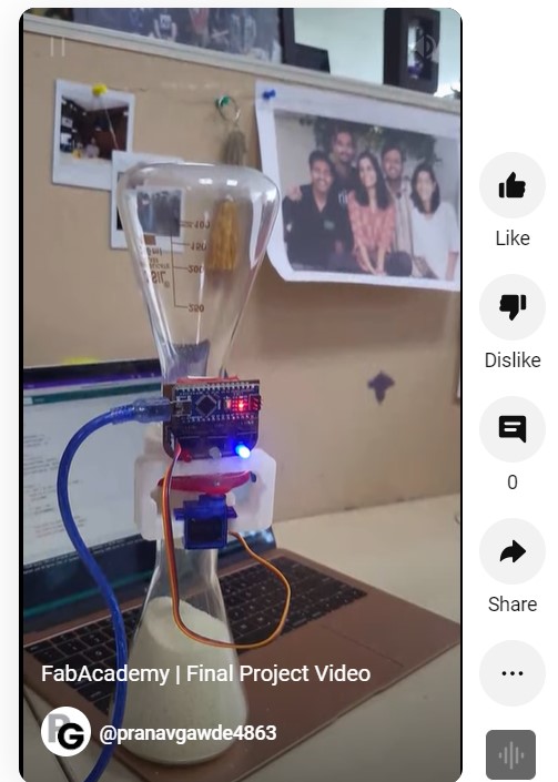
In software, obviously we need to update the code based on the improvements in the electronics hardware. Along with that, the code can be optimised much better as well.Final Product: Hero Shots
Summary Slide
Final Video
Hero Shots
Final Video v2
Download design files
HourGlass_Assembly_CADElectronics_CAD
Disk designs attempts CAD
Holder designs attempts CAD
All PCBs attempts EasyEDA files
PCB 2 Gerber files
PCB 3 Gerber files
PCB 1 Gerber files
Arduino code