2. Computer aided design
In Computer Aided Design, this week we had to explore 2D rasters v/s vector designs, 3D designs, renders, animation, simulation, etc. Let's first start with exploring what exactly these terms are if not known already. Also let's list down softwares to use to work on these designs.2D Design - Raster
What are raster files?So, wikipedia says, in computer graphics and digital photography, a raster graphic represents a two-dimensional picture as a rectangular matrix or grid of square pixels, viewable via a computer display, paper, or other display medium. Refer to the image below:
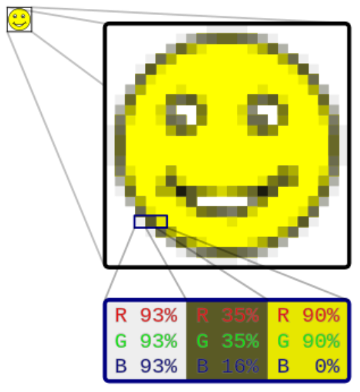
So if you look at this image, you will understand that rasters have a defined dimension and resolution. If you expand it, it will pixelate.
Why and for what reason are raster files used?
These are the different types of files that can be made using 2D raster designs:
Exploring GIMP
For exploring raster files, I have already had a good hands on with Photoshop since years, so this time I thought of trying new things. I tried to keep it in alignment with my office work so I don't have to spend separate time for these activities. Hitting two birds with one!So I tried to use GIMP software for exploring raster designs. Here are the steps I followed:
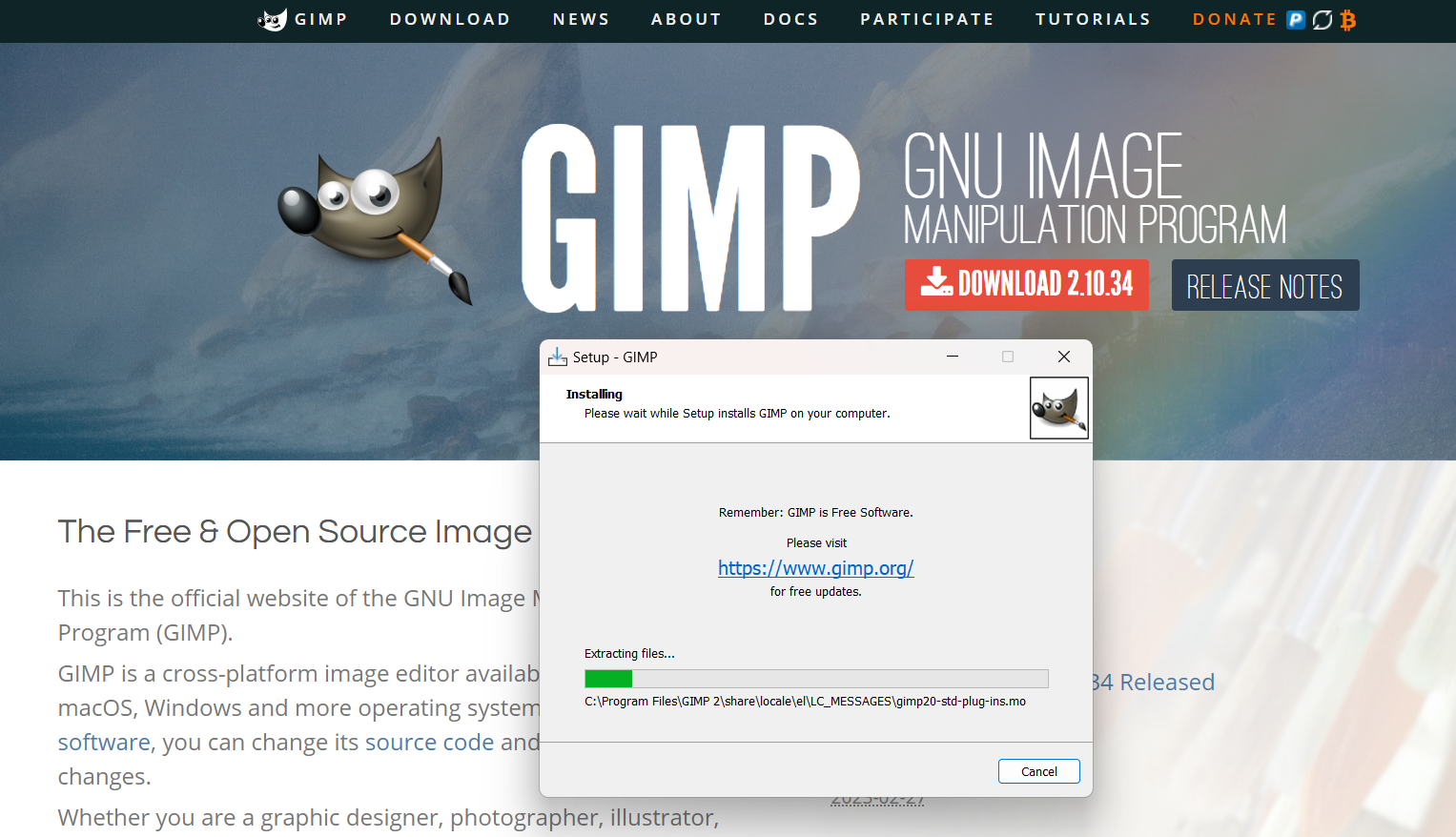
Step 1: Installing GIMP
GIMP is an open source software and can be easily installed within minutes. Th steps are pretty much intuitive.
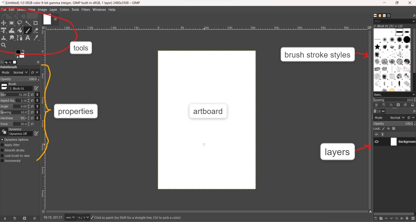
Step 2: Understanding the user interface
As shown in the figure below, the interface for GIMP is easy to understand actually. The tools panel is prelocated on the top left side and the properties of the selected tool is visible just underneath that. The brush stoke style can also be chosen from the top right corner panel. And there is also a layer panel in the bottom right corner. Rest all basic features are same as into any other similar software. You can start a new artboard from the File menu on the top.
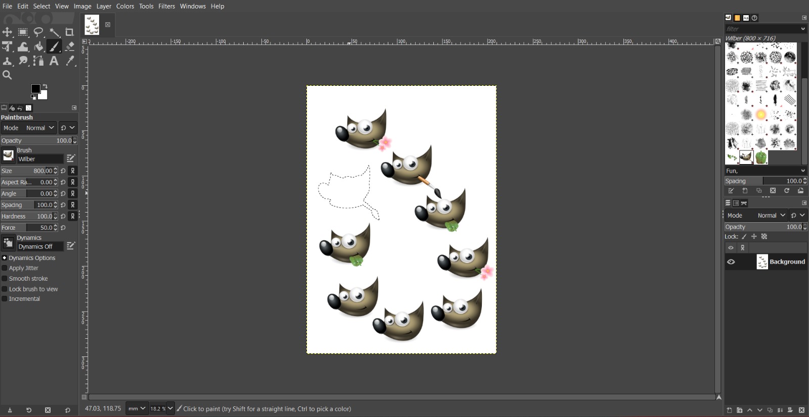
Step 3: Draw and Designing in GIMP
So I decided to try out designing a freestyle logo on GIMP. It is more convinient if you have a touch screen laptop or if you are using a wacom tab. Free drawing using a touchpad or mouse is a bit difficult. There are some inbuilt fun brush stroke styles to explore in GIMP as shown in the figure.
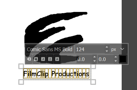
Step 4: Freestyle logo design
I used the simplest brush stroke tool to design the logo. Basically drawing directly using the touchpad. And used the add text tool with symbol "A" in the tools panel on the top left side. The properties of the text can be changed directly from the pop up that appears next to the text box as shown in the figure below
Step 5: Exporting the file
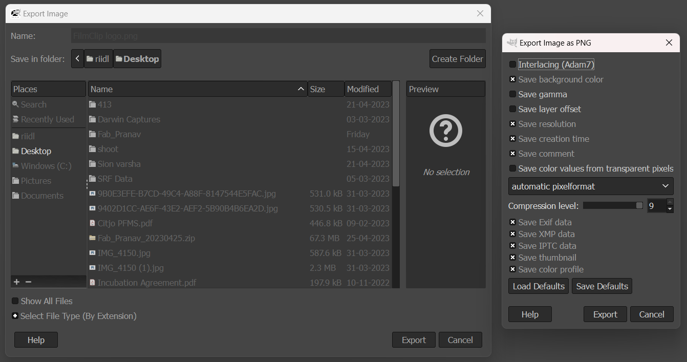
Before exporting, I cropped the artboard to the logo size using the crop tool in the tools panel. If you hover over the icons in the toolbox, you get a small description of the tool. Post that, go to files and then select export.
Then, in the export window, you need to choose the destination and the file type based on the extension you add. So if you name your file as "xxx.png" then the file type will be saved as png and next dialog box will appear(shown in the right in the image below) Then you can choose more specifications, if background color is needed or not.
Step 6: Final Logo

This is the final logo concept for the FilmClip productions that I was working upon. The startup FilmClip productions was my client and needed a logo design for his brand identity. This logo concept (one of the three I proposed) will be then redesigned on a vector file, as websites and other online platforms need .svg files i.e. scalable vector graphics
2D Design - Vector
What are Vector files?
According to google, A vector graphics file is an image that can be made infinitely large or small without losing quality. Common vector file types include .AI (Adobe Illustrator), .EPS (Encapsulated Postscript), and .SVG (Scalable Vector Graphics).
Why and for what reason are vector files used?
These are the different types of files that can be made using 2D Vector designs:
Exploring CorelDraw
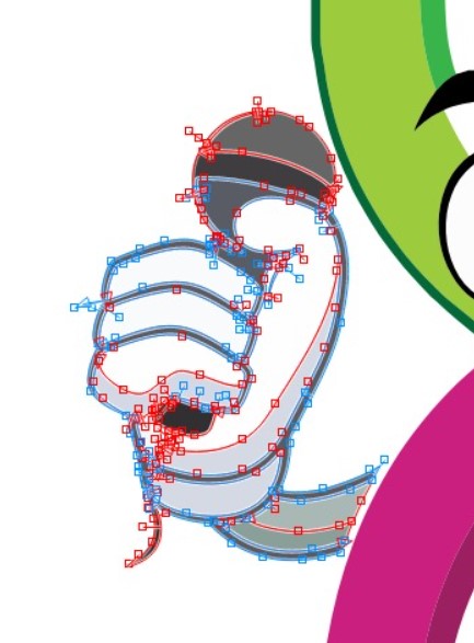
For 2D Vector designs, I have been using CorelDraw and it is my all time favourite.Step 0: Mascot ideation
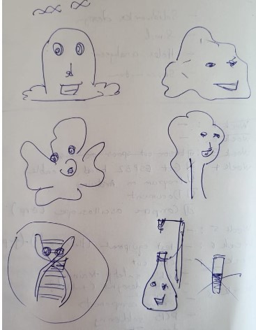
SO initially we need to know what is to be designed. So I had to design a mascot for an riidl organised event called Darwin. Darwin is One of India's Biggest Evolutionary Movements in Biology. This global celebration of biology of research enthusiasts facilitated through a panel of experts sharing cutting-edge research topics, talk sessions by established biologists, hands-on workshops, tours, Research Symposium - a paper presentation competition and Biohackathon - a hackathon to solve problems of the world biologically will be centered around Sustainable Biotechnology.
So since it is a bio event, I accordingly ideated few sketches and after discussion with the team we decided to go with the DNA mascot.
Step 01: Getting the software
CorelDraw is a licensed software but it is also the most widely used software in India. All print media vendors always demand .cdr files for printing in India. Our lab had licensed software access in our lab laptop, so it was easier for me to try out. But anyone can give it a try, it has a 15day trial version available on the website.
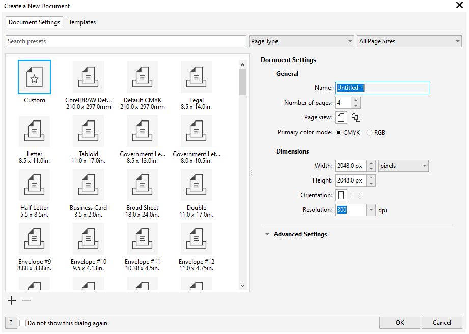
Step 02: New doc template
So, here's the document presets available to choose when you start a new document.
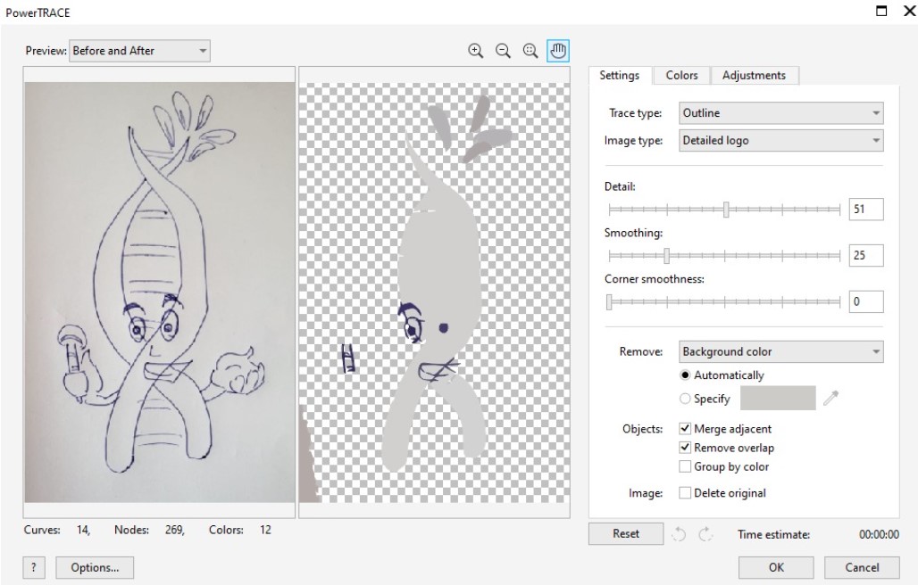
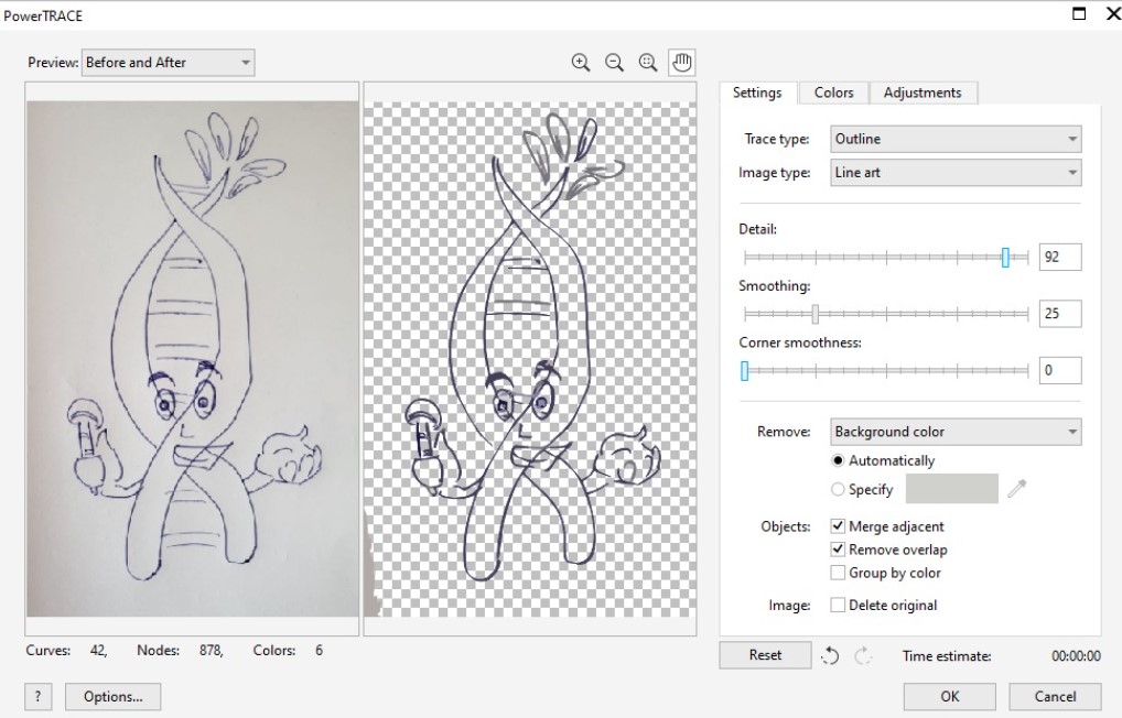
Step 03: Coverting raster sketch to vector
So first take a photo of the sketch and paste it into coreldraw. Then select the image and choose power trace option. In power trace, since our drawing is an line art, we should choose line art, ither options will give inefficient tracing as shown below:
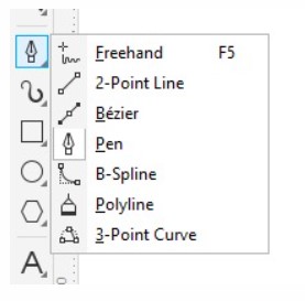
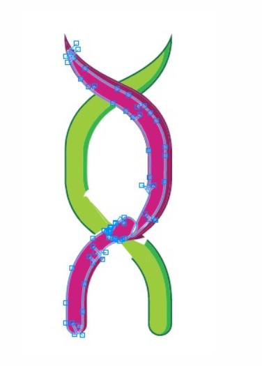
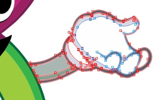
Step 04: Using the pen tool
Now, we have a rough trace of the sketch. Normally I just edit this vector file nodes to reshape it. Or sometimes I just redraw it if I want a more free style curve. Using the pen tool is quite easy. You click at the start point and then click at the next point between which you want the curve and before releasing the click, you drag you mouse in the direction you want to the curve to take shape. Then you click to the next point and repeat the procedure.
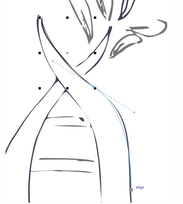

Step 05: Pen tool and raster to vectors
Likewise for other elements of the mascot, either I edit the converted vector points or draw my own vector loop in reference to the same. Other option is for example to get leaves and save time, we can download leave .eps files or .svg files or even .png or .jpg files can be used by converting them to vector as shown in step 03 above.

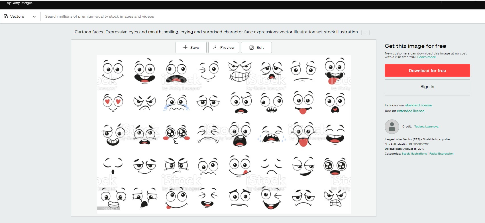
Step 06: Getting the face
For the face, I again borrowed it from stock files online as reference, then got them converted into vector and then either edit or redraw using pen.

Step 07: Adding the hands
Similarly I got the hands inspired and borrowed from some other old design of mine. br>
Step 08: Final touch
For the final touch, I added shadow, a border outline and similar small changes. The properties panel on the right side can be used to chane the line border width, style, color, etc. Another shortcut to add colors is the choose the object to color, and then on the extreme right side color panel, left click on the color for fill and right click on the color for stroke.
Step 09: Final file
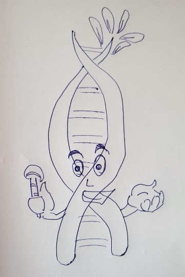
This mascot was used this year for the Darwin Conference printables and online media. Some of the print media samples are shown below:


Tips for CorelDraw
And here's what I want future me and anyone using CorelDraw for the first time or after a long time to remember.First thing first: SNAP ON
Always make sure to have this snap feature enabled in CorelDraw. It eases out 50% of the work when it comes to manually aligning elements to document corners, or similar aligning.
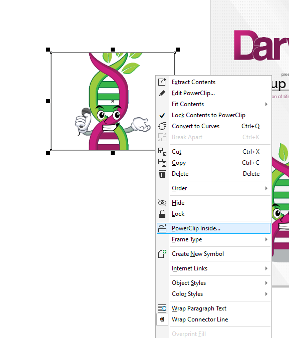
Second thing: PowerClip feature
PoweClip feature is yet another powerful tool from CorelDraw that can help you build multiple cool things by clipping things in within eachother.
Exploring Inscape
So apart form CorelDraw, I tried to experiment with some open source vector based software. I tried Inscape. Inscape is yet another beginner level vector based software. The best feature in vector designs is the use of pen and spline curves to draw your illustrations. Vector graphics can be scaled to whatever size and resolution you want without losing the quality of the curves.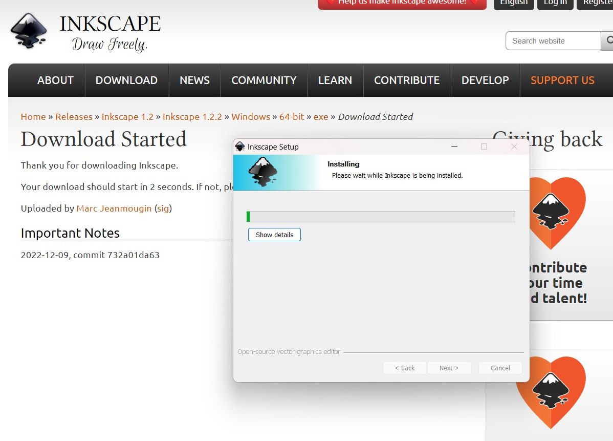
Exploring the Pen tool in Inscape
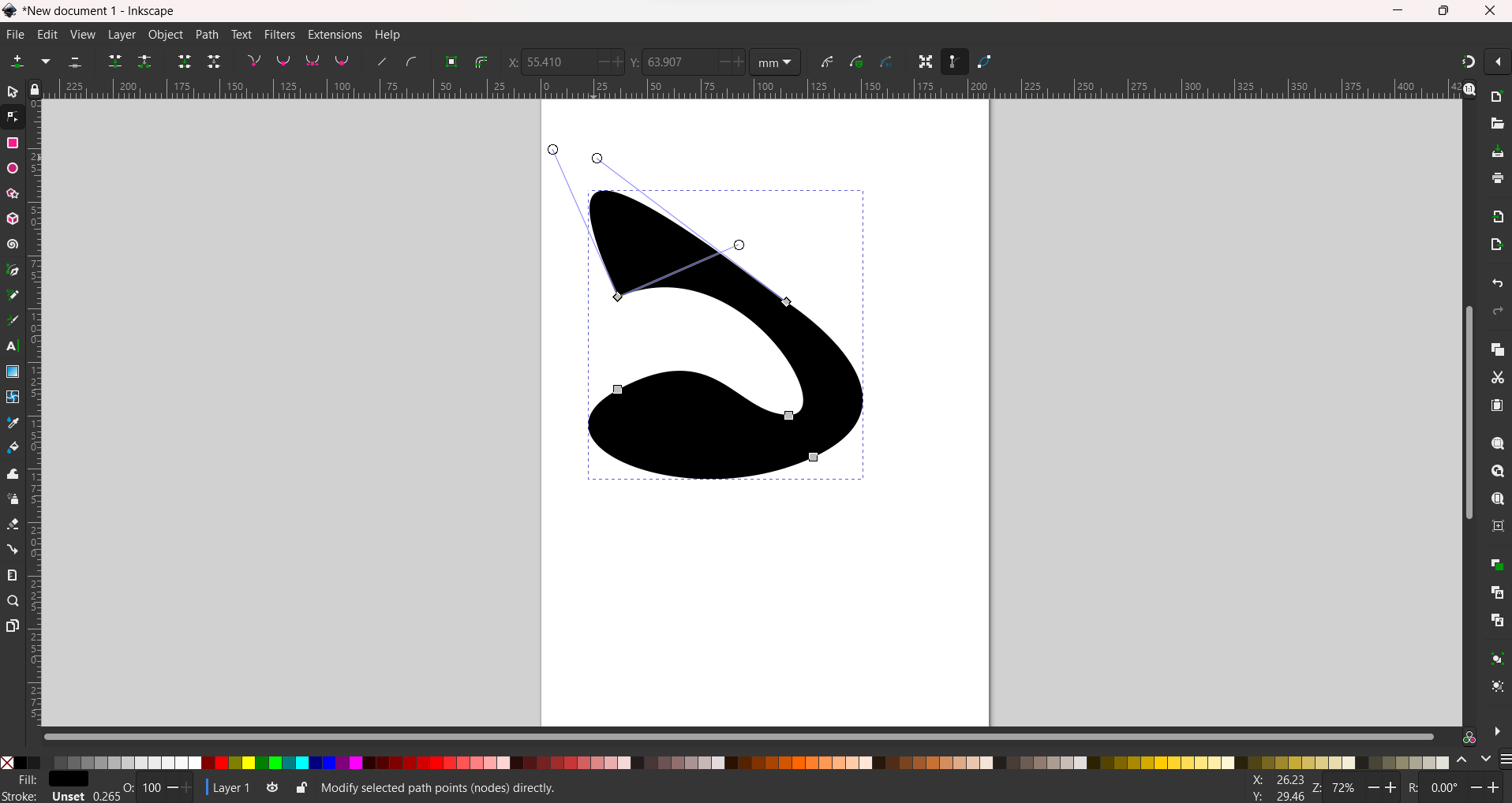
I am always interested into exploring the pen tool and freestlye drawing tool in every new vector software I try out. SO the only thing I tried on inskape is the pen tool if it is by any ways more convinient or efficient in its working than other vector softwares like coreldraw. It is more or less the same in inscape though. Corel has better option in the post porcessing of the nodes to move the angles and convert pen lines to curves and viceversa, which I couldn't find in inscape.
3D Design - CAD design
What are 3D design files?3D design is basically designing any product virtually in a software with all three dimensions (length, width and height) So as of now we are working in single plane for 2D designs, but in 3D design there are 3 planes. There are many 3D design softwares you can try. Blender is an open source software, while majority of the 3D CAD softwares are licensed and their subscription depends on the complexity of the design it can handle.
Why and for what reason are 3D CAD softwares used?
These are the different reasons you can use 3D CAD softwares for:
For CAD design, I have been using Autodesk Fusion 360 extensively since my engineering. But recently have shifted to Solidworks So here's some basics of solidworks and how to design things in solidworks:
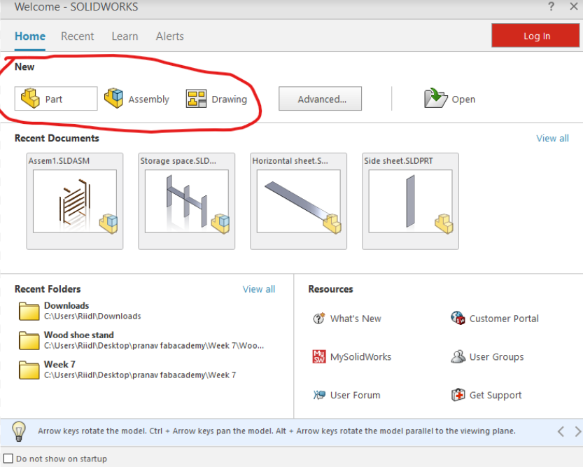
Step 0: Starting with Solidworks:
So Solidworks is the most extensive and widely used software. If you are new to 3D designing in general then, you can design any product that you see/use in real life, virtually in solidworks. It can be as simple as a ball or as complex as a car. Solidworks offers three things when you click on start > new. It is either a part, a assembly or a drawing.
Part: So a single part product if to be designed, then choose part. This is the elimentary one to start with.
Assembly: So when you have a product made of two or three or even thousands of parts together (in case of complex products), you need to make an assembly. An assembly is basically a collection of the parts.
Drawing: So once a part or assembly is made, the design dimensions, specifications and instructions are denoted in a drawing to be able to convert the 3D design visualisation into a 2D drawing for printing and quick information transfer.
Solidworks Part
Step 1: Designing a part: SketchingFirst thing, once you start a new part file, you need to start by choosing a plane to sketch upon. Usually, you are building from bottom to top then you start with top plane. The sketch tools are explained in the image below
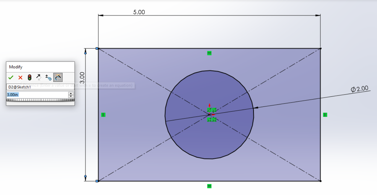
Step 2: Designing a part: Extrude boss
Features > Extrude Boss
Once you have a fully defined sketch, you can extrude it with a desired height from the Extrude Boss option in the features panel.
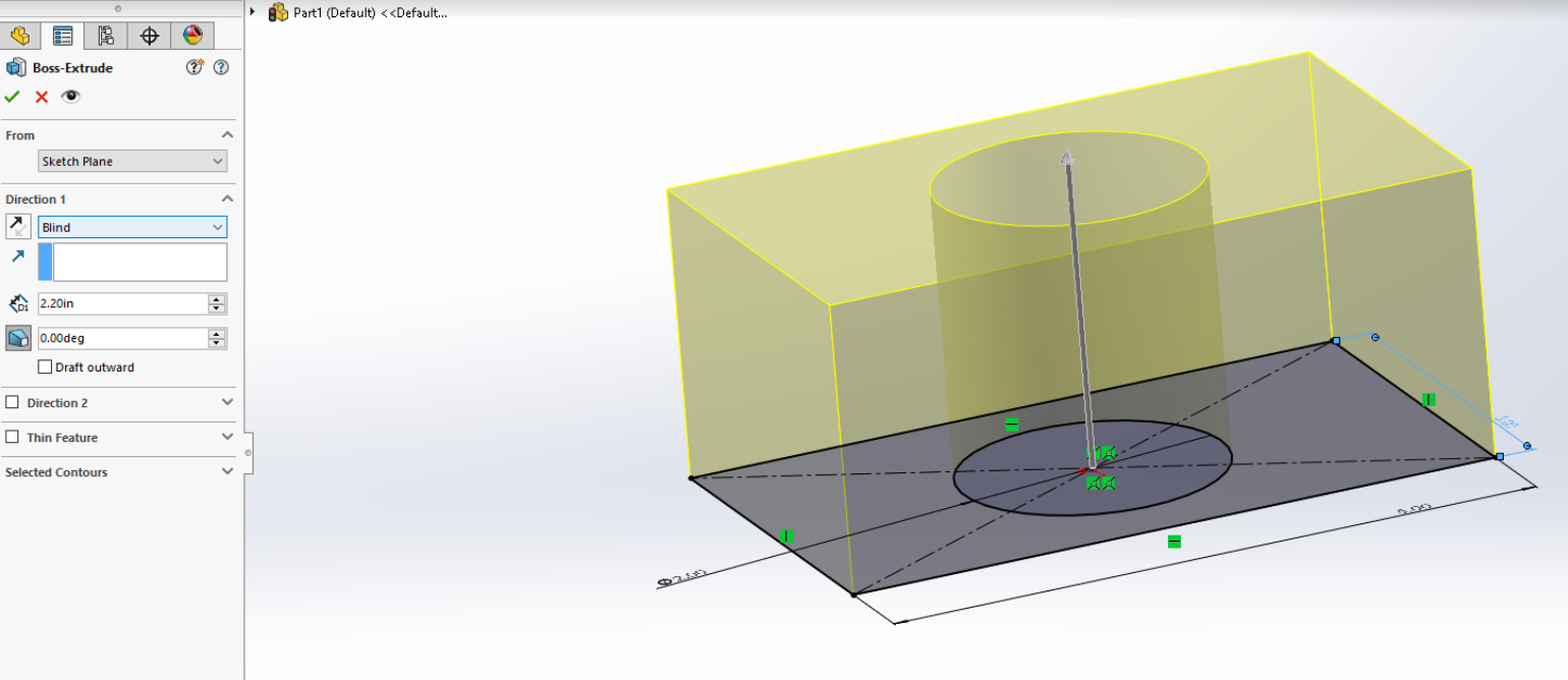
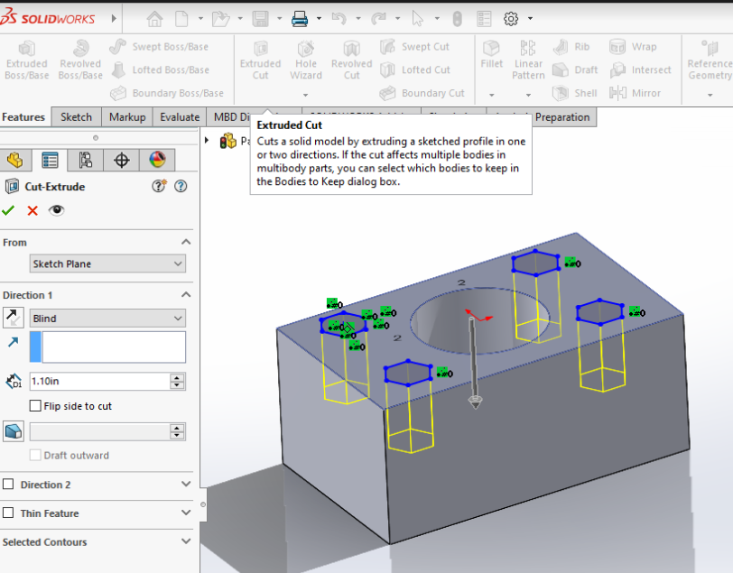
Step 3: Designing a part Extrude cut
Features > Extrude Cut
You can choose to draw another sketch on top of a plane and then extrude cut it through the object as shown below:
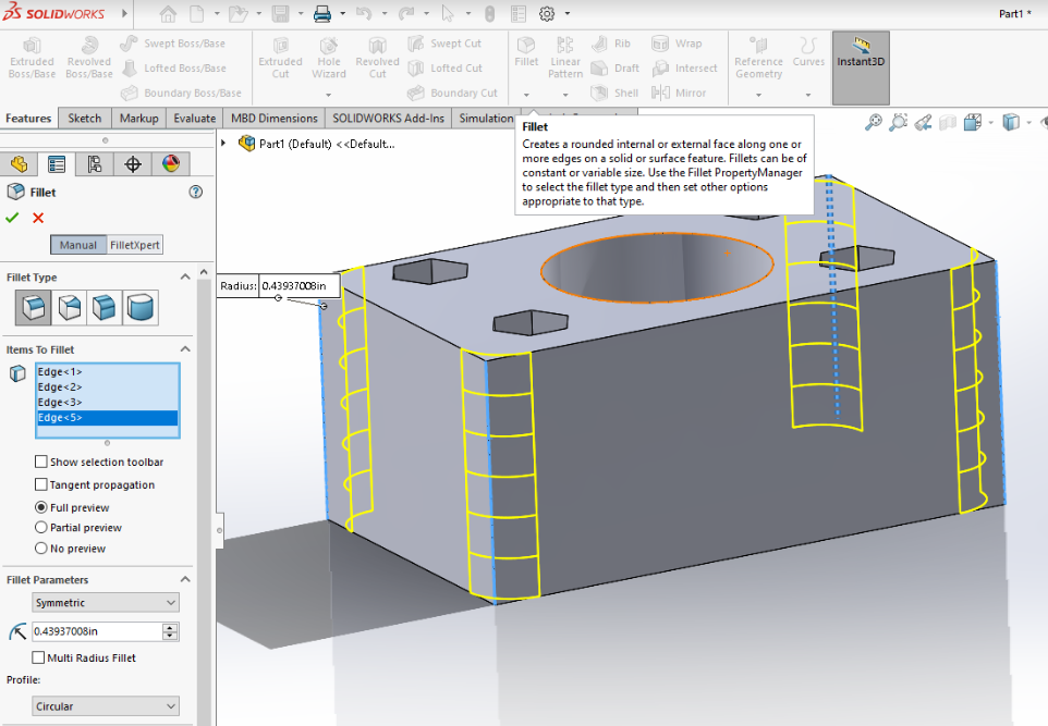
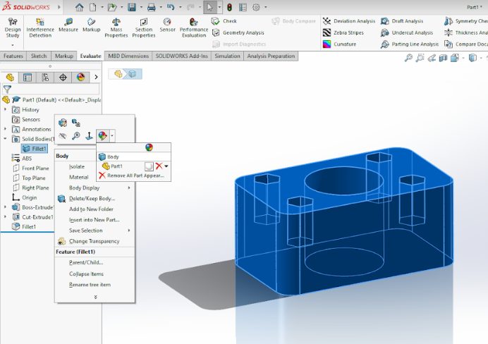
Step 4: Exploring other features: Extrude/cut Revolve, loft, hole, fillet, chamfer, etc
Apart from the basic boss extrude and cut, you can also explore revolve, loft, hole, fillet and chamfer features. THe fillet feature for example is shown below and is used to smoothen the sharp edges on your product.
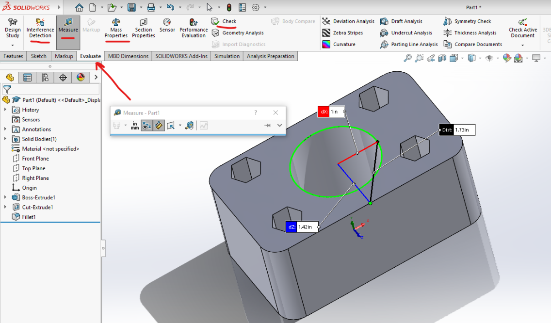
Step 5: Evaluate, Adding material, add appearances, etc
Evaluate > Measure Evaluate panel has multiple alternatives to try as marked below. One of the most significant one is measure, which you can use to measure point to point distance between two points on your product or even angles.
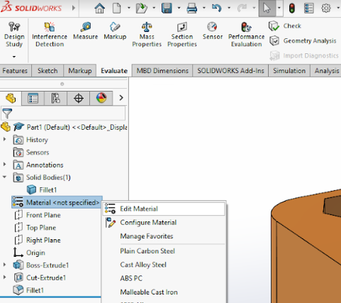
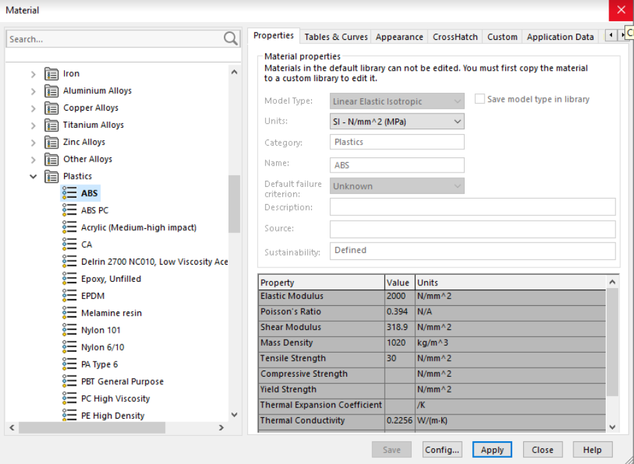
Another significant tool is mass measurement which can be useful to define the weight of the product, provided you have defined the material properly. Here's how you can define the material for your product:
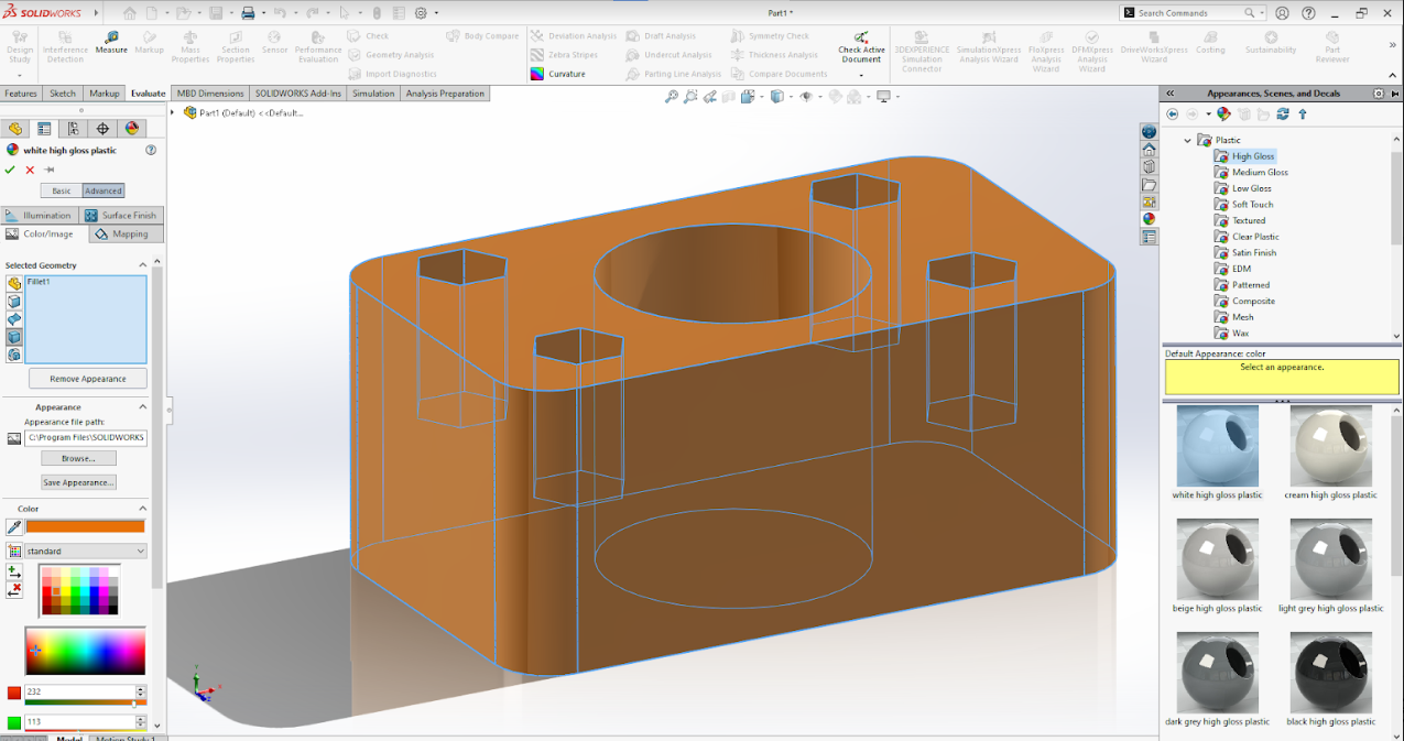
You can also set appearances of your product as shown below. YOu can define color and material texture as well as shown:
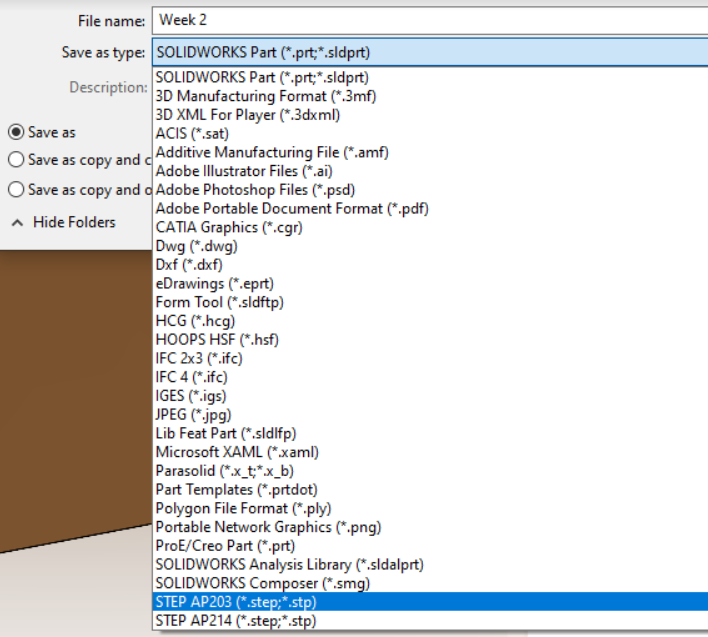
Step 6: Save and Save as files as:
Once the part is ready, make sure to save it as File > save
You can save a copy of the file it in different file formats as well as shown in the figure below:
Solidworks Assembly
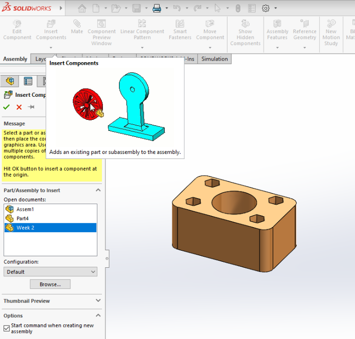
Step 7: Designing an assembly: Adding partsNow once we have 2 or more parts to assemble together, we need to start a new assembly.
File > new > assembly
In an assembly, first thing you need to do is to add parts as shown below. If the part is not open already in solidworks, then you can browse from your files.
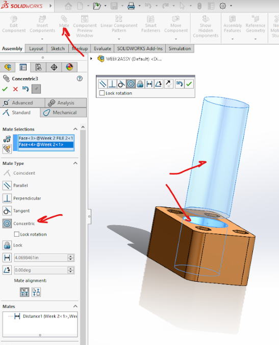
Step 8: Designing an assembly: Assembly mate function
Once you have 2 more parts, you can fix/orient them with respect to each other using assembly mate function. There are various mates possible as seen below
Step 9: Exploded view
YOu can show an exploded view as well where your parts can be popped out in animation to show the order of assembly. It is often used in larger assemblies where you have more than 5 or 10 parts. It is also beneficial to showcase nuts and bolts mounting in the assembly in exploded view. But not in the case of current product.
Final Product
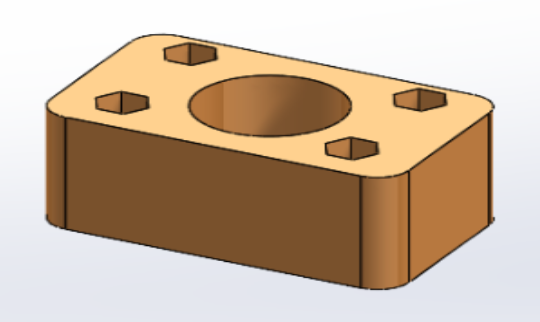
The product was needed as a mounting block for my another project. I had marked the hex extrude cuts to add nut with interference fit in there, we can also use inserts for 3D printed parts actually but I prefer nuts with interference fit. And the central hole was for a rod to be hold in position. It should have free movement in 1 rotational and 1 translational axis but not in any other and that was th purpose of the block. I will add the final photo of the block when in action in the project.
Modelling for final project
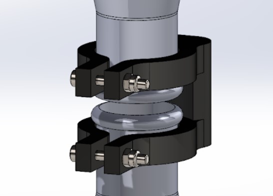
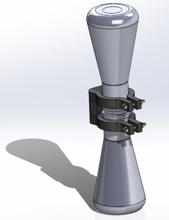
So as per the requirement of the assignment, we need to utilise this solidworks learning for our final project. Well I have designed the holder for my final project. The photos and videos of the same are as below:More details of the same can be found in the Final Project page linked.
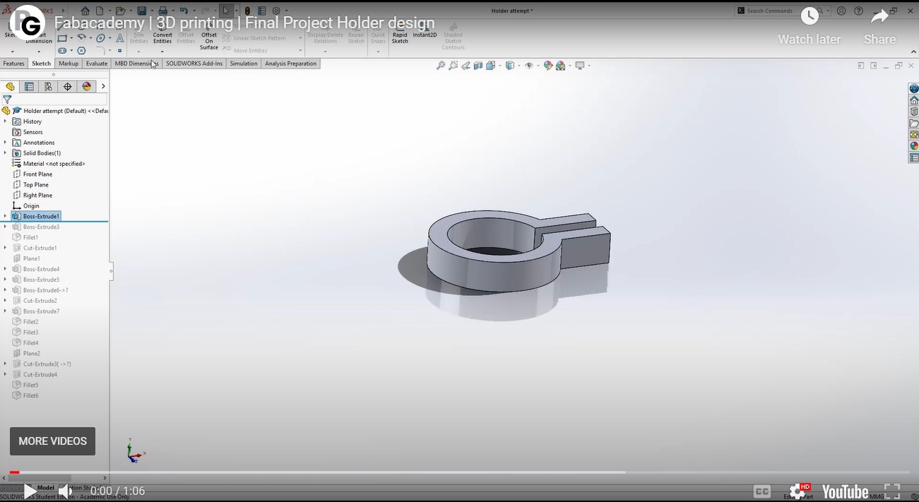
Example of the final project CAD modelling
I designed the holder on solidworks by measuring the outer diameter of the flask and then made an adjustable design using a 4mm bolt and nut to tighten as shown below:
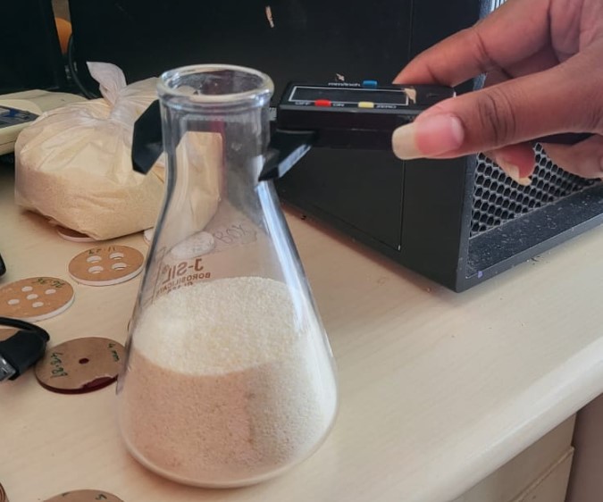
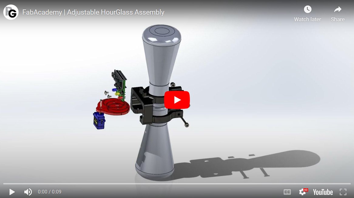
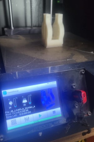
The design was 3D printed and the test looks as shown below:

CAD Rendering
Rendering has couple of definitions in my opinion. When a product is just in its ideation phase, and is explained using sketches, a clean 2D sketch with the effects of a 3D view is also a render. These renders are developed in raster softwares or actual paper sketches most of the times.Another type of render I think is the 3D rendering. It is more of an natural visualisation of a product in an 3D environment with proper lights and shadows, backgrounds, material textures, reflections, etc These types are renders are highly used in advertising industry and can be exported in the format of still images or even videos. The softwares used for such renders are Soildworks Visualise, Keyshot, Blender, etc
Exploring blender
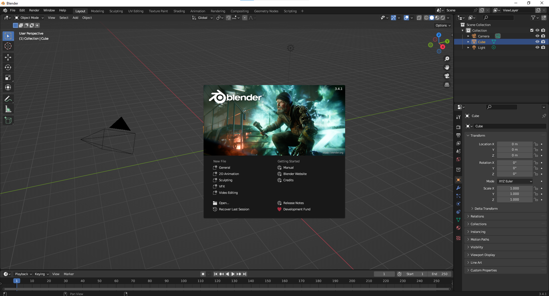
For rendering, I used to use either Solidworks render or Keyshot. Keyshot is a specific software just for rendering and I have used it a lot. But this time I tried to explore Blender. Blender is an open source software and real fun to use as well.So first here's how to install it in simple terms. You can directly download the latest version from the website as shown, and the installation is pretty simple
Blender has many possibilities, right from CAD designs, 2D animation, sculpting, VFX, and video editing. But I tried using it for basic CAD design and then image rendering.
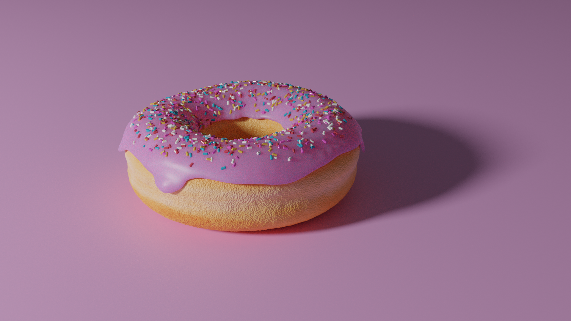
I followed the famous Donut experiment on youtube by BlenderGuru.

Here's the final product renders in stages for the blender Donut
Stage 1: Designing the basic CAD
So initially the basic cad design is similar to designing in any other CAD software like Solidworks. You sketch, extrude or revolve, etc. In Blender, things can be controlled a bit better in terms of randomness. Whereas, solidworks is a software which is more bound to the rules and restricts random uneven design explorations. So Blender and Solidworks both have their preferred types od designs to be designed in that particular software.
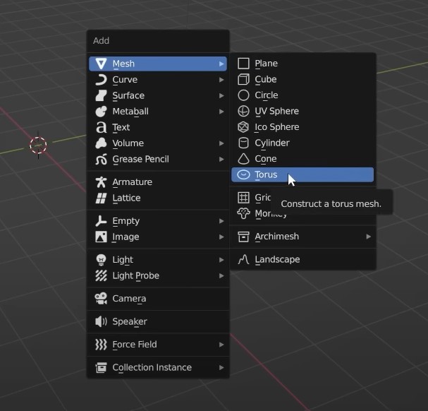
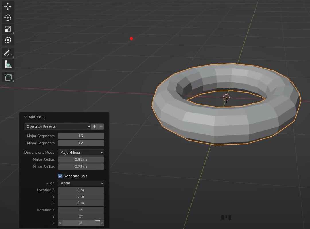
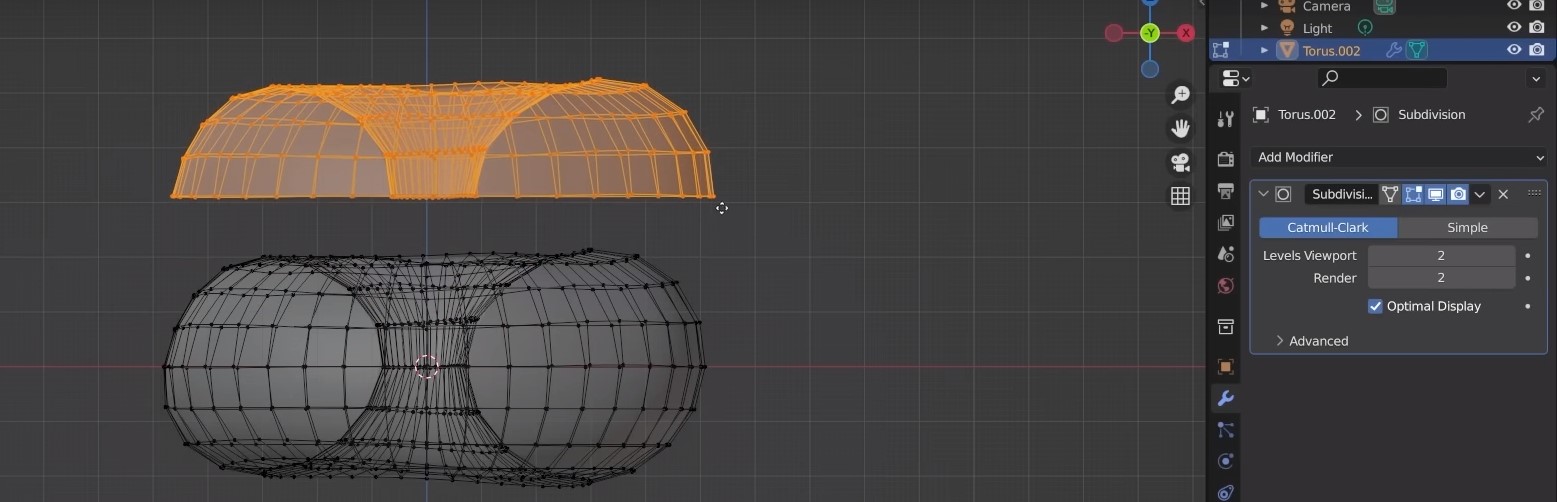
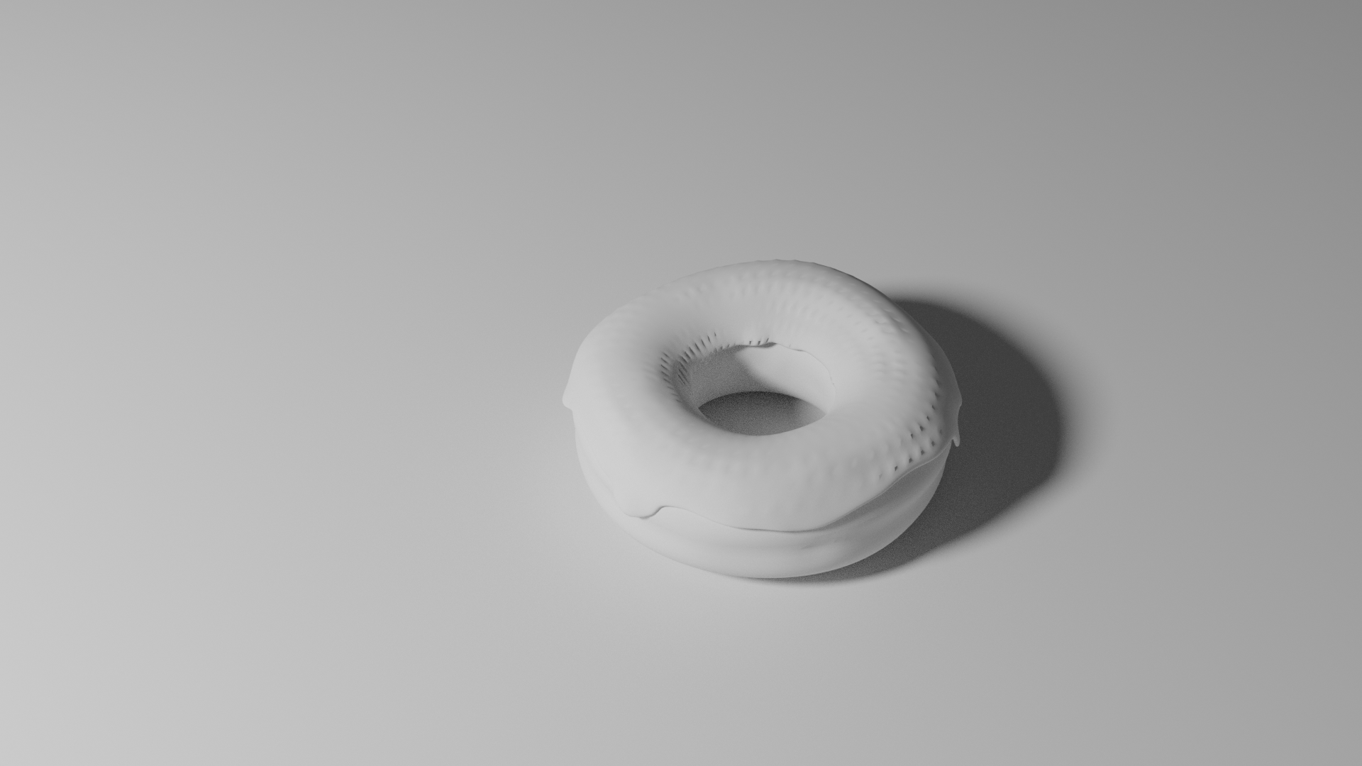
Making the torus:
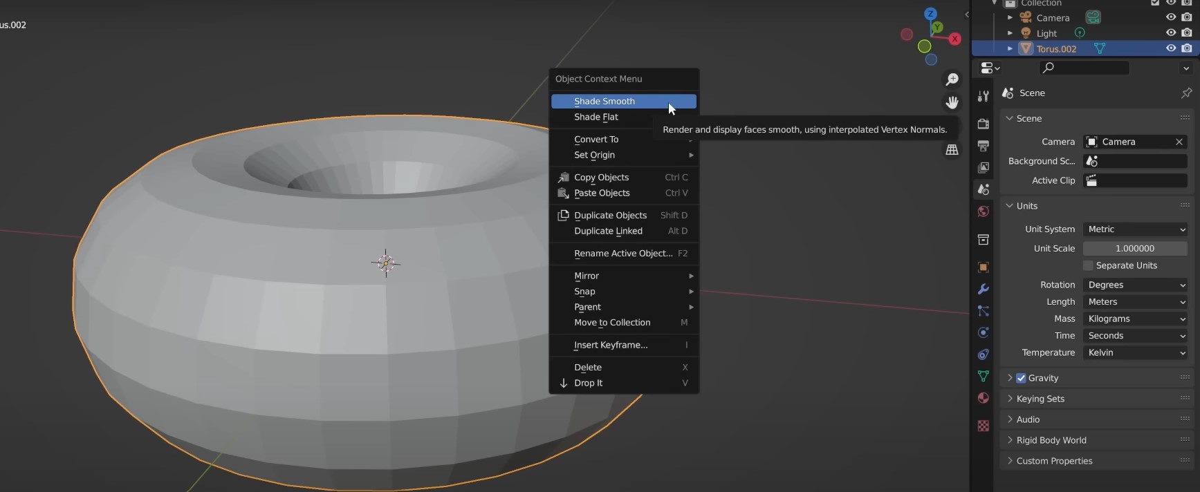
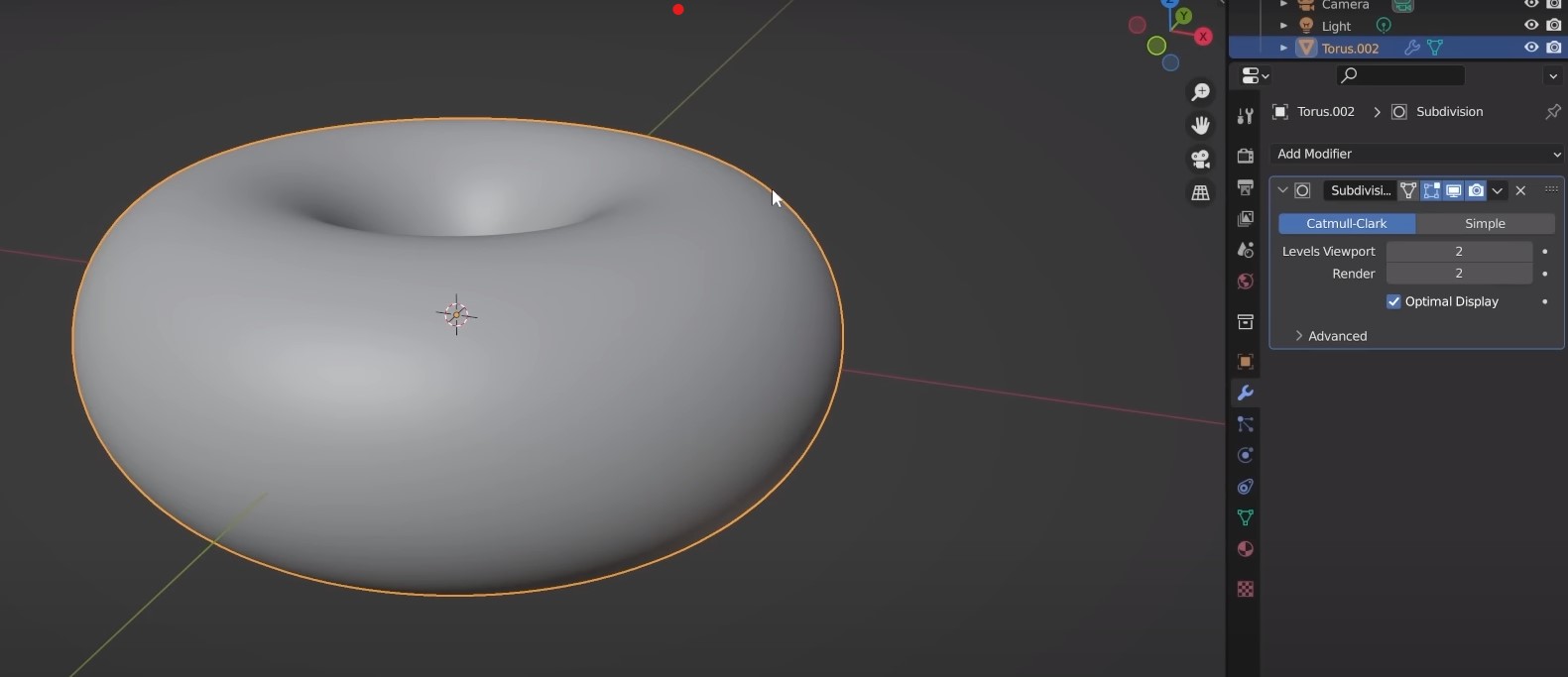
Smoothing the shape:
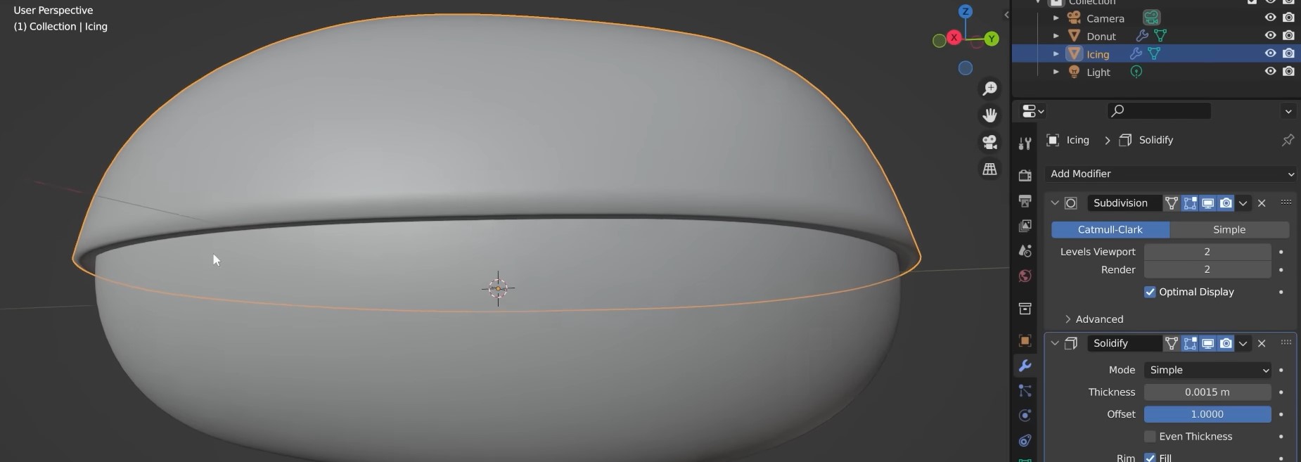
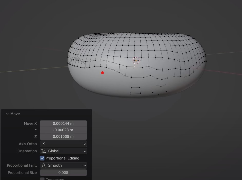
Adding top layer icing:
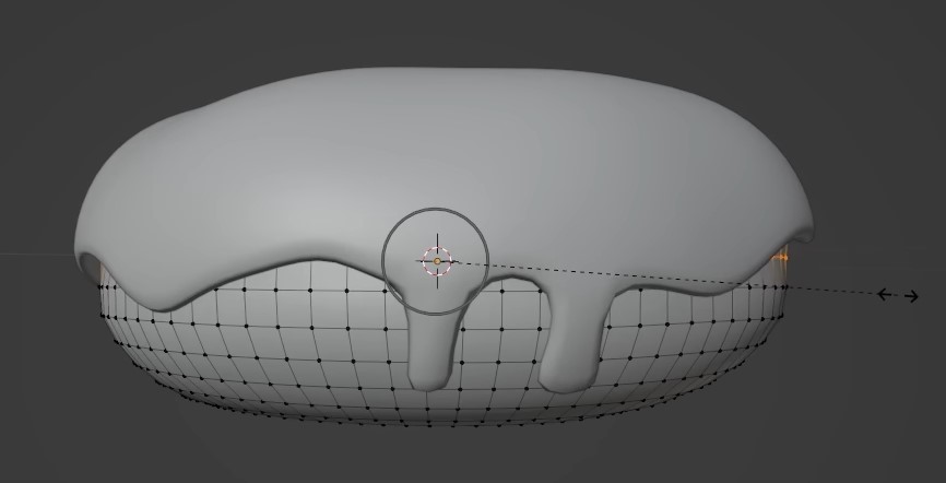
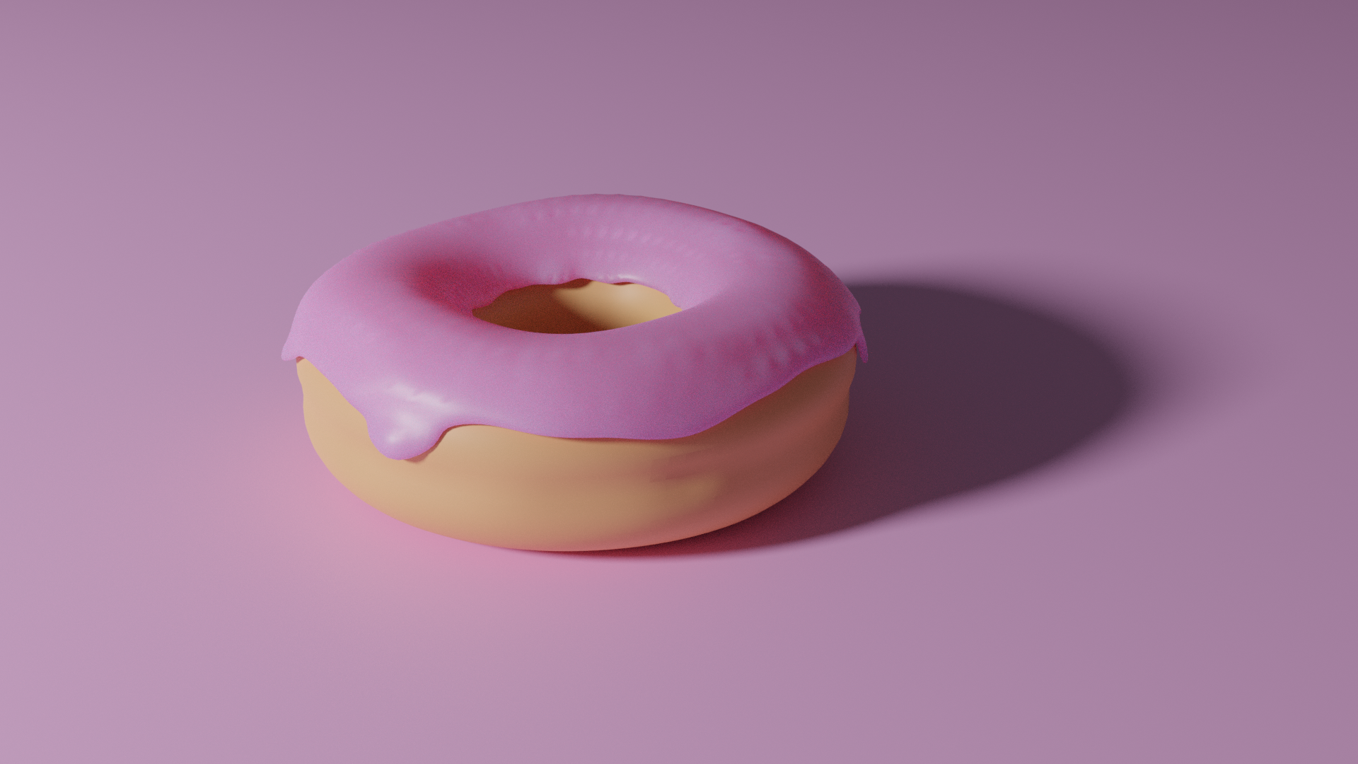
Stage 1 final product view render:
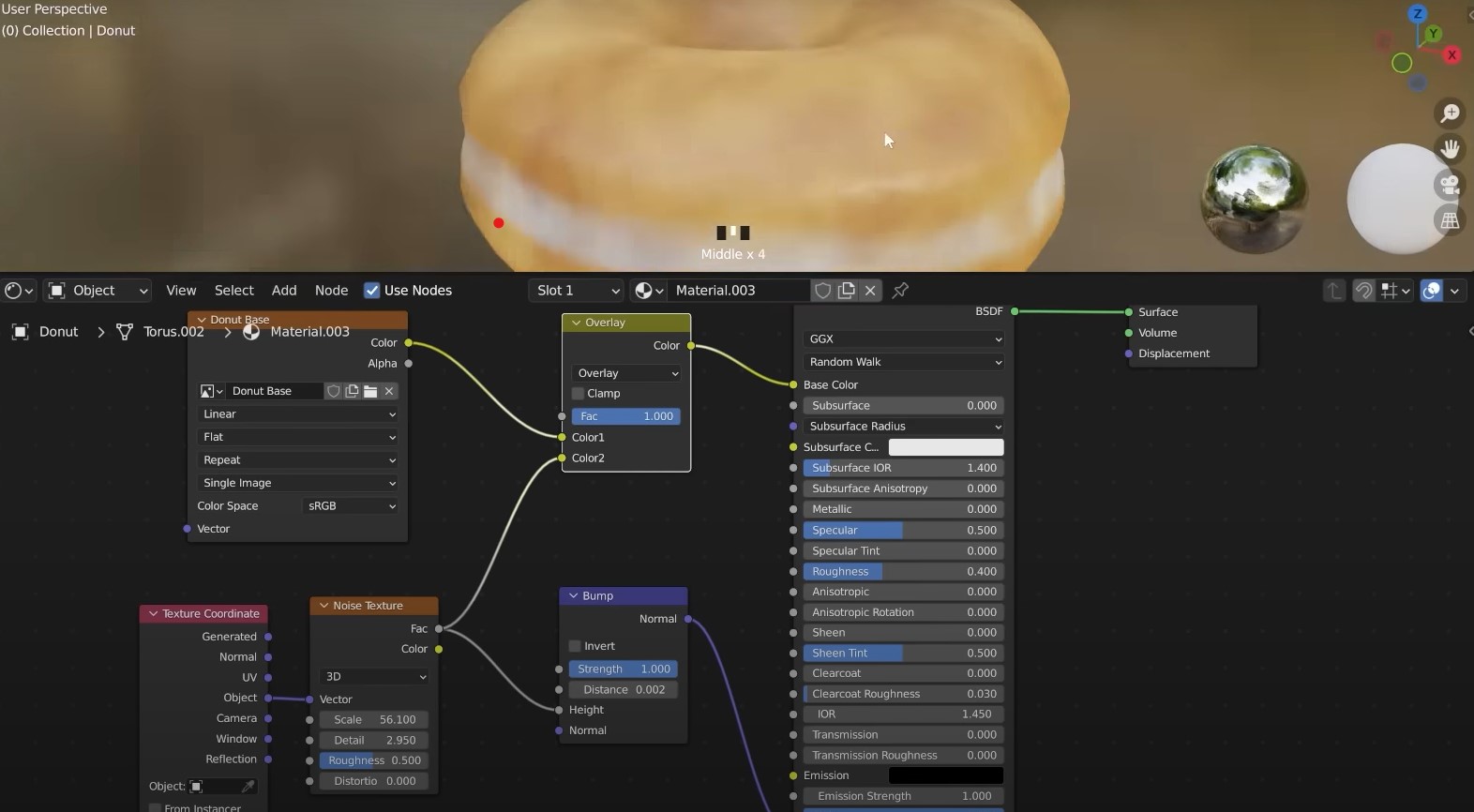
Stage 2: Adding appearances
Since the basic design is done, we can add details like colour, lights etc to the setup. It is more or less like setting up a visual photo studio in Blender.
Adding colors:
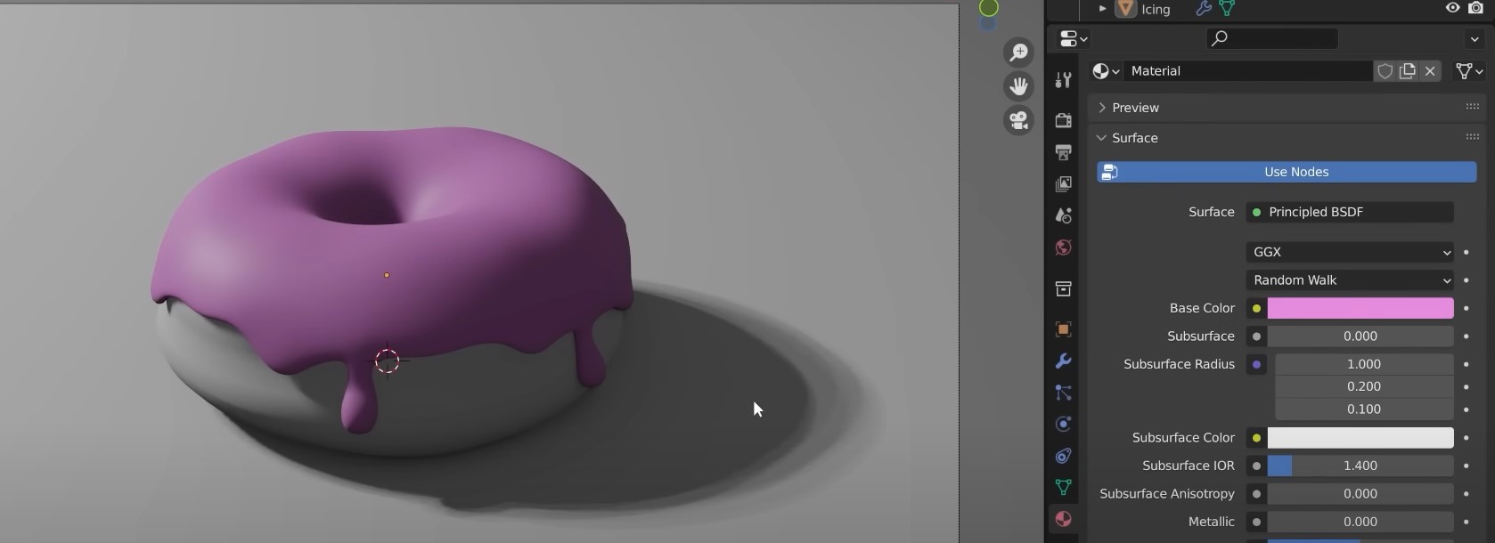
Adding lights and shades:
Stage 2 final product view render:
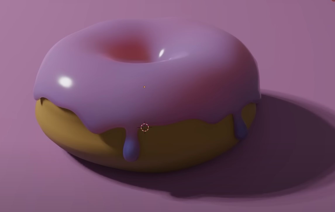
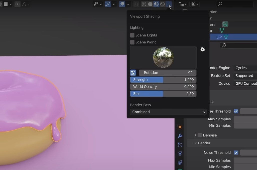
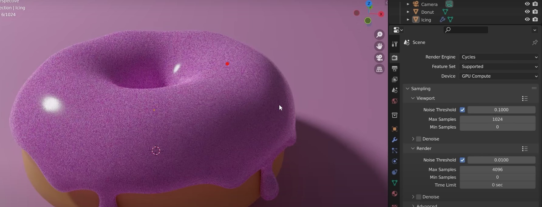
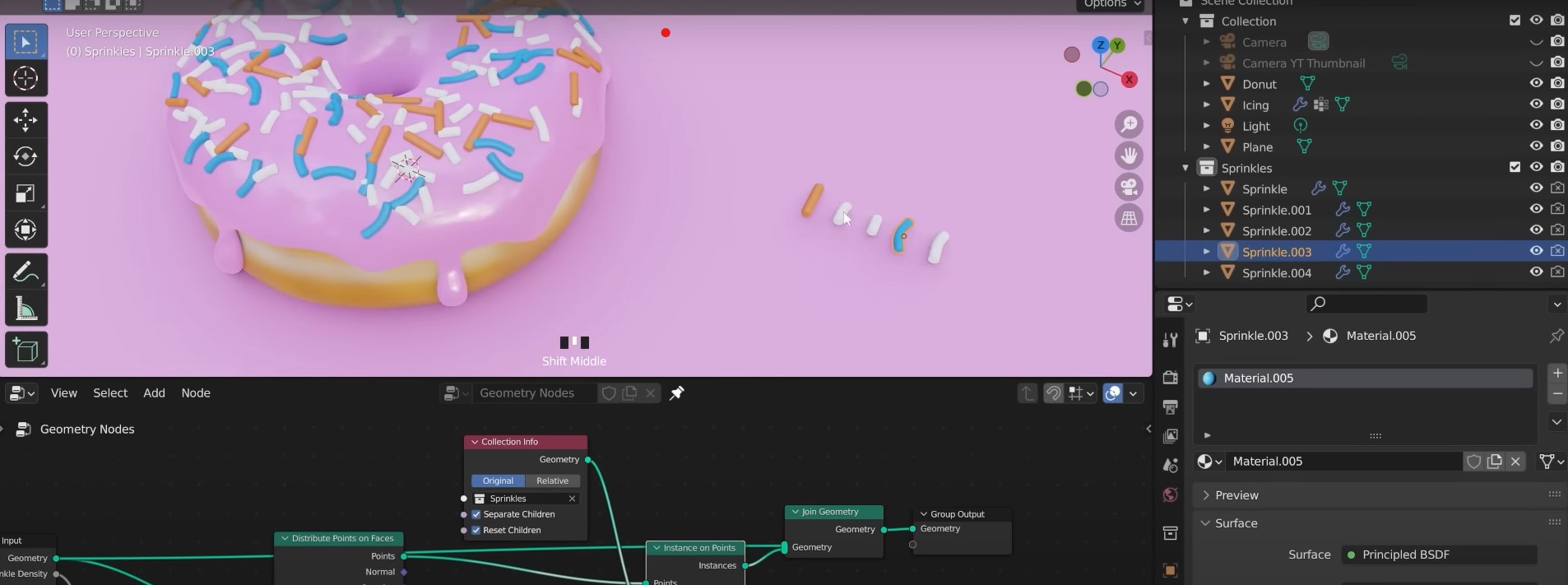
Stage 3: Adding texture details, etc
To make it more realistic, you can go in more details by adding proper bread texture to the donut base for example.
Adding texture & sprinklers
Stage 2 final product view render:
Download design files
GIMP file zip - FilmClip LogoCorel file zip - Darwin Mascot
Solidworks file zip
Blender file zip