6.Electronics design
In this week, we work in our electricas design for the schematic and the PCB. In this part I feel confused because it is my firs electrical design.
Create Electrical Schematics in Fusion 360
In Fusion 360 can we design stages of design electronic circuit, the schematic design and printed circuit board (PCB) layout. This sofware we work in, we place components, manipulate components, wire the schematic, add power, define values and create a PCB.
In this exercise our instructor taught us how to design a schematic with the ESP32 microcontroller.

Step 2, on the left side, there is the search engine to add components, we choose the desired one and place it in the work area.
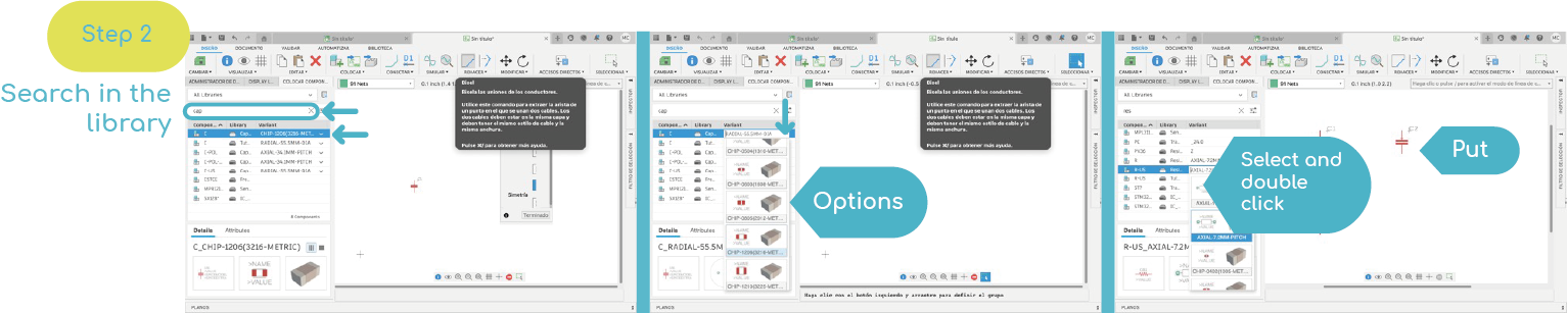
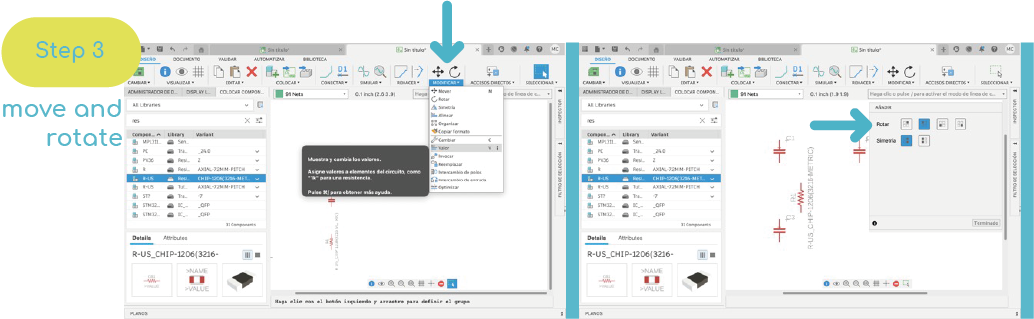
Step 3, to move and rotate the components we have the tools on the top side.
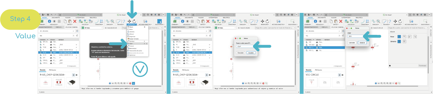
Step 4, to add a value, you must click with the mouse and choose the "value" option and place the desired value.
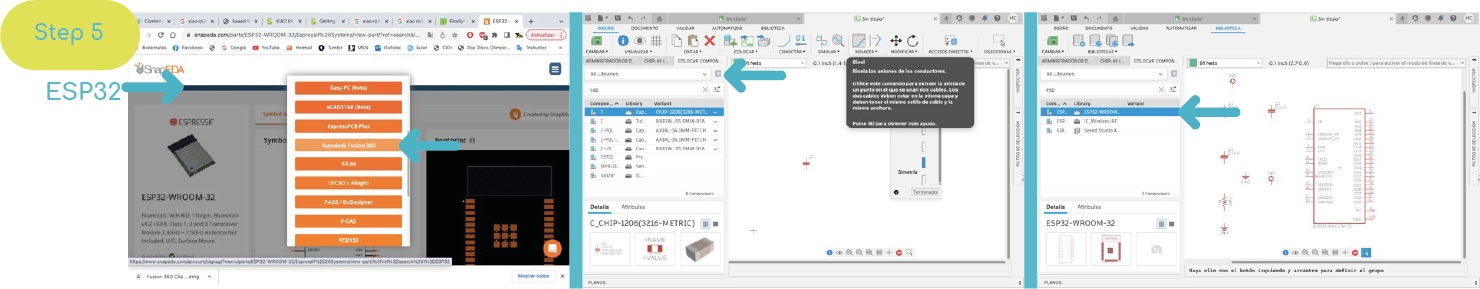
Step 5, for elements that are not in the library, they must first be downloaded, in this example the microcontroller library is downloaded "ESP32".
Go to a page where you can download items, Then I add the link: ESP32
Step 6, to connect the components, in the upper drawing area, you can draw lines to connect the components.


Schematic
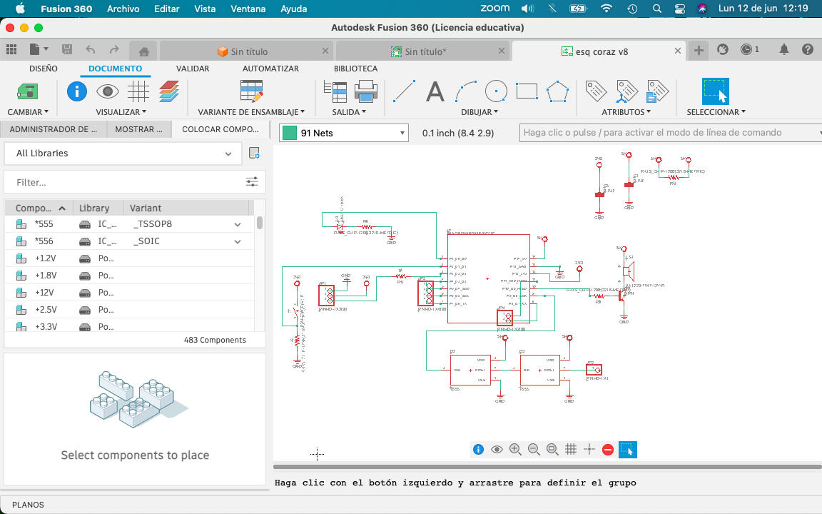
In this schematic I have added a red led, a buzzer, a switch, a space for a sensor, two neopixels connected and in the rest of the pins, I will place an output. For this schematic my instructor Oliver helped me a lot, because I don't know the subject.
Below I show the list of components generated by the Fusion 360 program.
List
| Part Value | Device | Package | Description |
|---|---|---|---|
| C1 0.1UF | C_CHIP-1206(3216-METRIC) | CAPC3216X135 | Capacitor - Generic |
| C5 0.1UF | C_CHIP-1206(3216-METRIC) | CAPC3216X135 | Capacitor - Generic |
| D2 1655 | 1655 | LED_1655 | Ws2812b 5050 Rgb Led / Adafruit Industries 1.6 mm |
| D3 1655 | 1655 | LED_1655 | Ws2812b 5050 Rgb Led / Adafruit Industries 1.6 mm |
| D4 LED_RED | CHIP-FLAT-G_1206 | LEDC3216X75N_FLAT-G | RED |
| JP1 PINHD-1X3/90 | PINHD-1X3/90 | 1X03/90 | PIN HEADER |
| JP2 PINHD-1X1 | PINHD-1X1 | 1X01 | PIN HEADER |
| JP3 PINHD-1X4/90 | PINHD-1X4/90 | 1X04/90 | PIN HEADER |
| JP4 PINHD-1X2/90 | PINHD-1X2/90 | 1X02/90 | PIN HEADER |
| LS1 AI-1223-TWT-12V-R | AI-1223-TWT-12V-R | XDCR_AI-1223-TWT-12V-R | BUZZER |
| Q2 NPN | NPN_SOT23-BEC | SOT95P237X112-3N | NPN - Generic TRANSISTOR |
| R1 R-US_CHIP-1206(3216-METRIC) | RESC3216X70 | - | Resistor Fixed - ANSI |
| R2 1001 R-US_CHIP-1206(3216-METRIC) | RESC3216X70 | - | Resistor Fixed - ANSI |
| R3 3000 R-US_CHIP-1206(3216-METRIC) | RESC3216X70 | - | Resistor Fixed - ANSI |
| R4 000 R-US_CHIP-1206(3216-METRIC) | RESC3216X70 | - | Resistor Fixed - ANSI |
| R5 000 R-US_CHIP-1206(3216-METRIC) | RESC3216X70 | - | Resistor Fixed - ANSI |
| S1 B3U-3000P(M)-B | B3U-X000B3U3000P(M)-B3000P(M)-B B3U-3000P(M)-B | - | Ultra-small Tactile Switch |
| U2 XIAO-THRUHOLEHYBRID-SMT-THT | XIAO-THRUHOLEHYBRID-SMT-THT | XIAO-GENERIC-HYBRID-MODULE14P-2.54-21X17.8MM | Seeed Studio XIAO Series Through-hole |
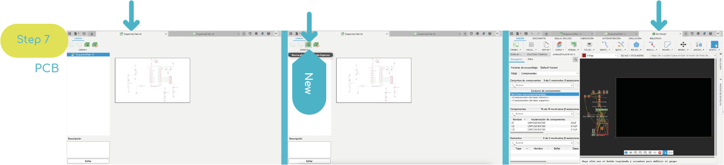
Step 7, Change the overview window and create a new PCB. the program will create a new tab, where we can see the actual appearance of the routing.
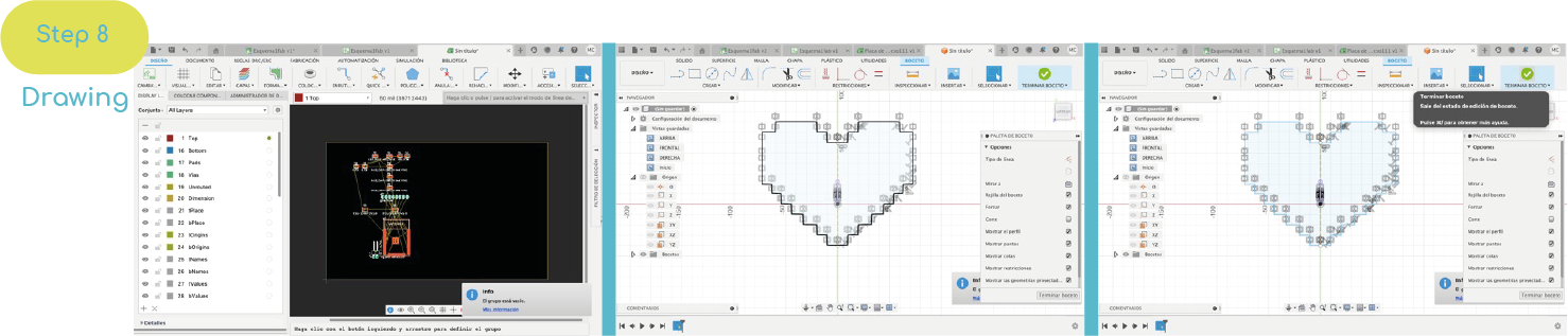
Step 8, To change the shape of the PCB, first save the document, then create a new layout and draw a sketch.
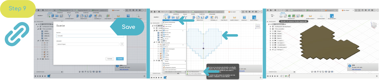
Step 9, then a new design must be created and a scketch drawn. Then exit the sketch, go to "create" and choose the option to create a printed circuit board and choose to make it "associative".

For design guidance, the following considerations should be taken: It must accurately reflect the design, provide clear information so that it can be reproduced or modified. A bill of materials must be generated, the signals must flow from left to right. Avoid crossover of components. The minimum distance between tracks and the edges of the board will be 5 mm.
The width of the track must be sufficient to allow the passage of the maximum current that will circulate through the track.
| Track width | Maximum current |
|---|---|
| 4 mm | 10 A |
| 2 mm | 5 A |
| 1.5 mm | 4 A |
| 1 mm | 3 A |
| 0.5 mm | 2 A |
| 0.2 mm | 0.5 A (500A) |
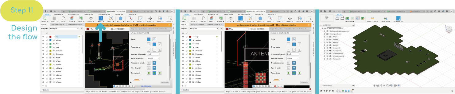
Open my first electrical design
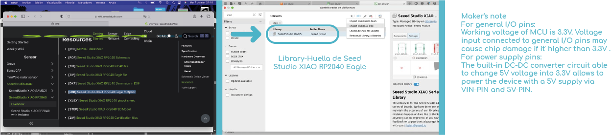
I started by choosing a microprocessor that would fit my final project in size and function. In this case the XIAO RP2040. To have it in the Fusion library, download it from the following manufacturer's page: XIAO-RP2040
Not sure what kind of sensor to use, I wanted to start my design with the space needed for each PIN and some elements to give me an idea of the size and complexity.
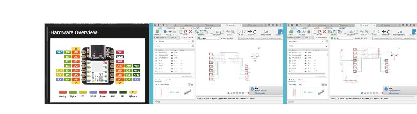
Design
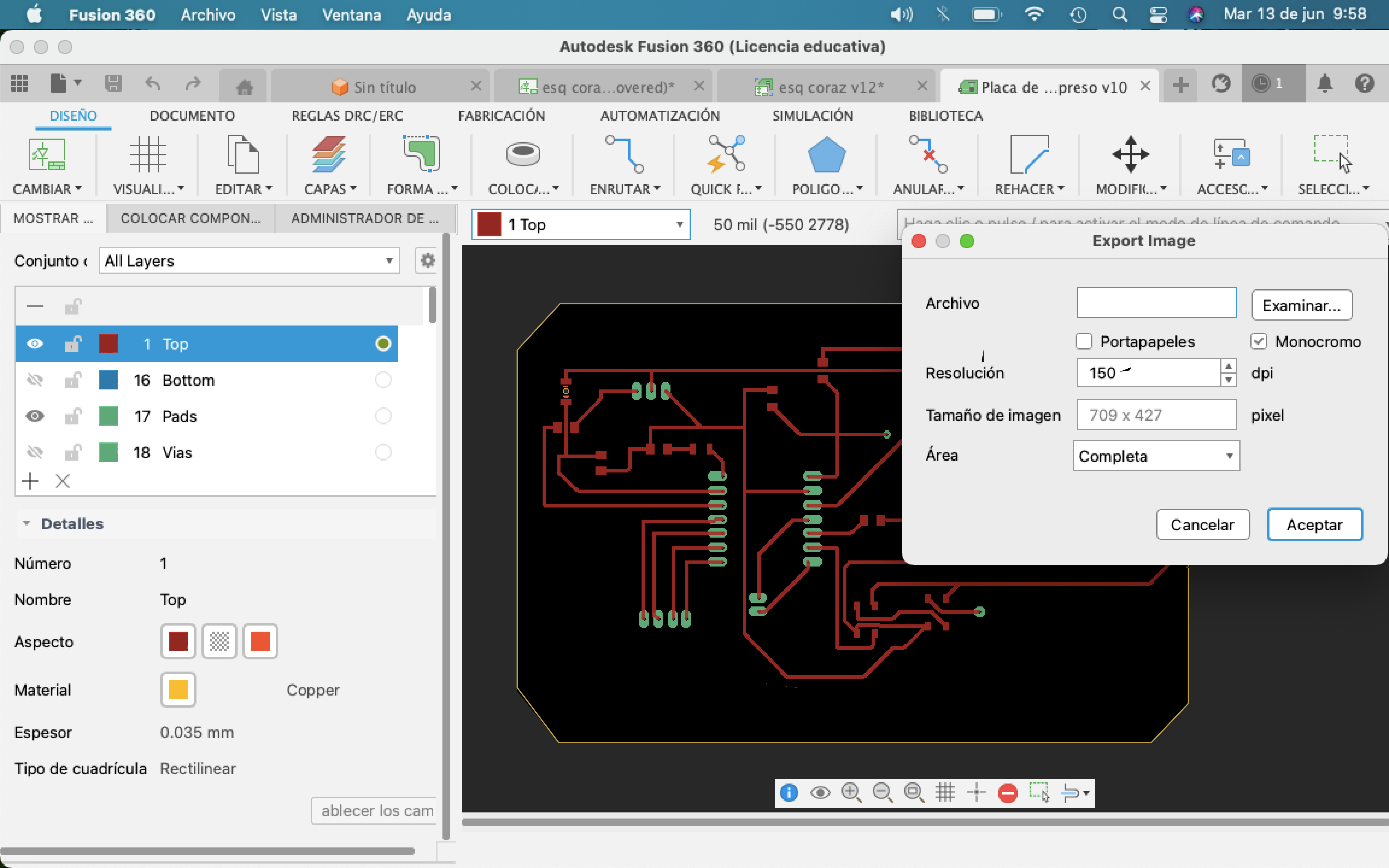
For the design of my first PCB, I did something simple, the schematic is the same, also the list of components.
To get the image, write in the "export" command found in the blank panel, and choose the image option, in the window that opens, select the "moncchromatic" option and choose the option 300 dpi, to save it in a high-quality format.

Team Work
For teamwork, a digital storage osiloscope and an XIAO rp2040 microcontroller were used, with the program loaded from my week 4 "Neopixel color".
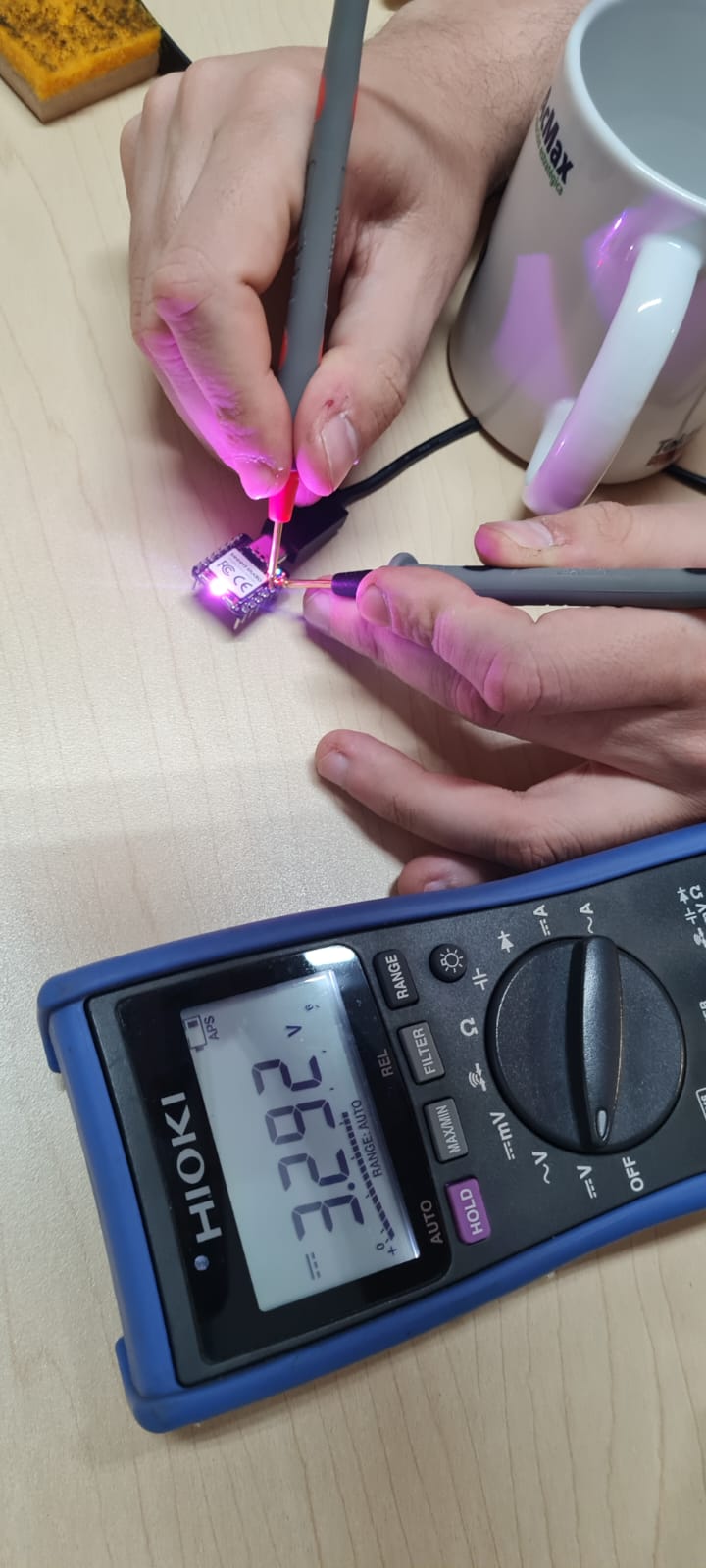
We use 2 types of measurement: the osiloscope and the multimeter. The XIAO was given power through a type "C" cable and connected to the oscilloscope on the ground and the pin with which the code was loaded.
The Y axis (vertical) measures the voltage and the X axis (horizontal) measures the time), with the knobs we can scale the graph.
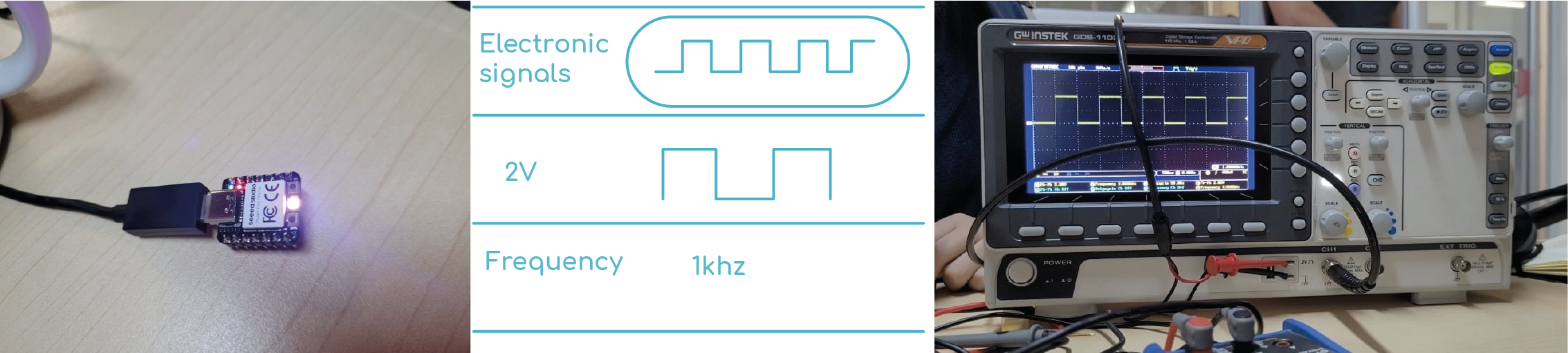
Video
When we see the output of the XIAO we can see a square signal, this measurement is from pico to pico, with a frequency of 1khz at a signal of 1000 times per second.
My colleague Fávell used his ESP32 and obtained as a result a square signal going from 3.3v to 0 every second, ...page of Fávell.

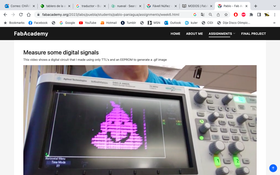
My partner Pablo made a digital circuit, he only used TTL and an EEPROM to generate a .gif image...page of Pablo.
Schematic
In this week I learned the order that has to be carried out for the design, order and structure of a PCB, in addition to the use of the electrical part of Fusion 360.
Files.
The subject is quite new to me, that's why it was difficult for me, but I liked learning more about the process of a PCB in fission 360.