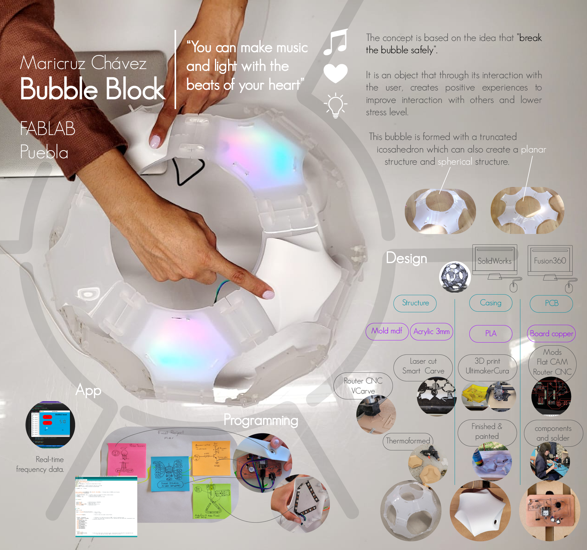
Hello, in this section of my site, I will tell you in detail about the result of my final project, initially my final project was a game for children with Autism to improve socialization through fun stimuli, but it ended up being a game for my moments of stress.
It is better to lower stress levels with a distractor to help lower stress with a different activity, the activity I am referring to is making music with your heartbeat.
In our day to day we experience high levels of anxiety and stress, when we prolong it for long periods of time, we can develop heart diseases, high blood pressure, diabetes, depression, among other conditions. Relaxation techniques can slow the heart rate and reduce blood pressure.
In the journal Cerebral Cortex published on April 21, 2015, a team of scientists led by the University of Cambridge and the MRC prove that there is a relationship between our heart rate and our decisions and emotions. In one of the experiments, 42% of the participants showed a significant improvement in their ability to repeat their heartbeat after previously listen to it through a stethoscope, this had allowed them to concentrate their attention to their own heartbeat signal. Several of them showed a significant improvement in their performance, with a stronger brain signal known as heartbeat evoked potential (HEP) throughout the brain. Knowing our body can help us listen to our hearts to be more aware of our emotions and improve our decision making.
In order to have a playful tool for this purpose, i designed a buildable game that have the ability to listen your heartbeat with visual and audio response.
Throughout the weeks of the FabAcademy I was carrying out several projects related to digital manufacturing, these exercises could lead to the development of our final project. In my case, I directed most of my exercises, but it was in week 15 (Wildcaed week), when I began to manufacture my structure.
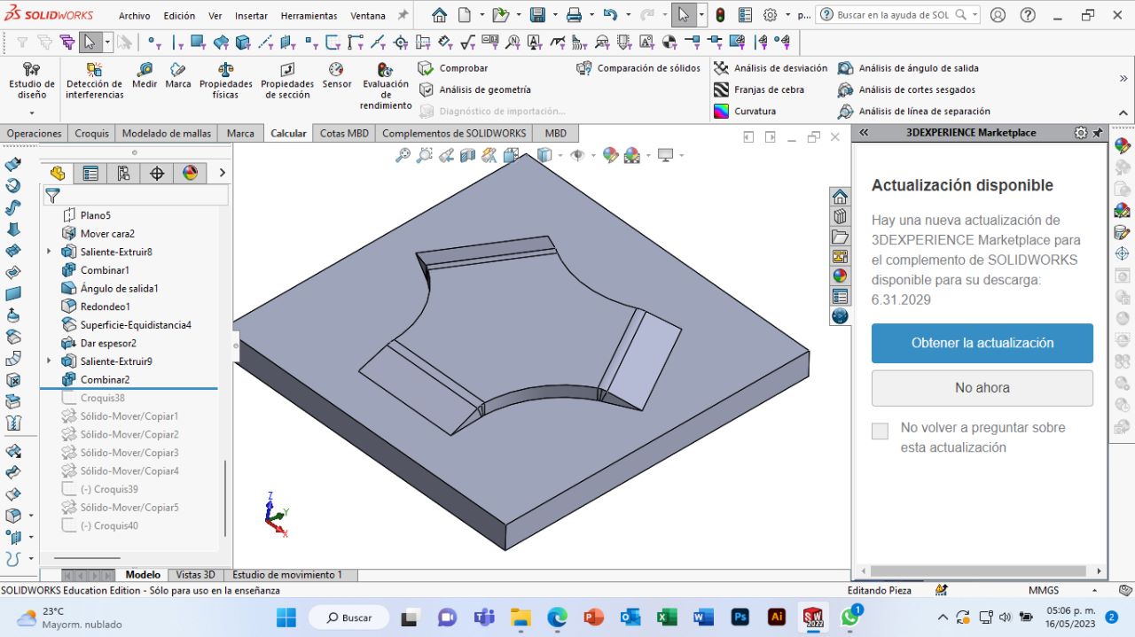
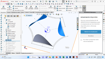
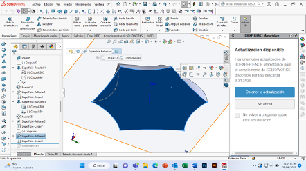
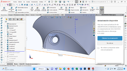
First I designed my file in solid works to make a flat piece with the help of my project that I did in week 3 "Computer controlled cutting".
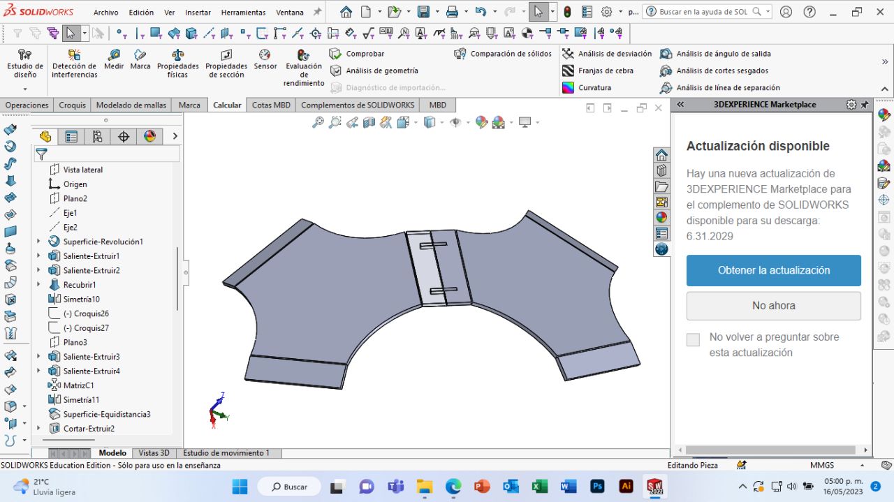


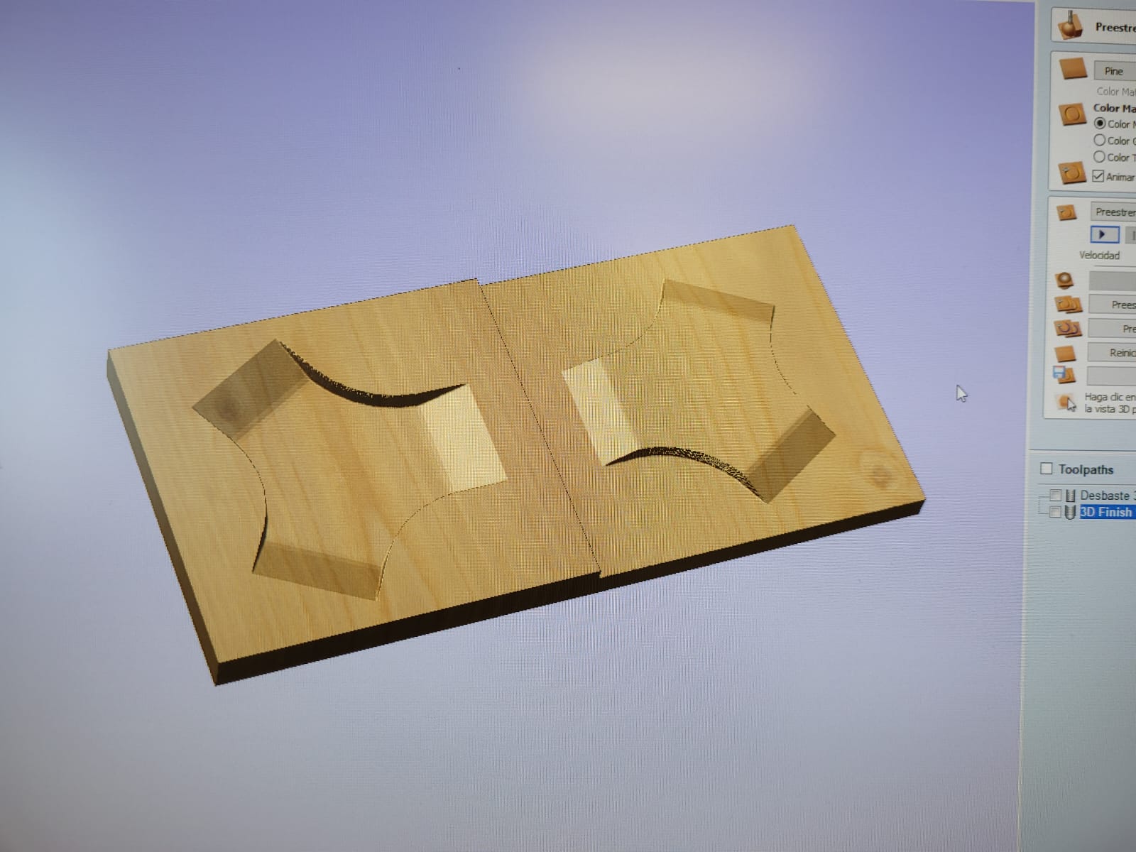
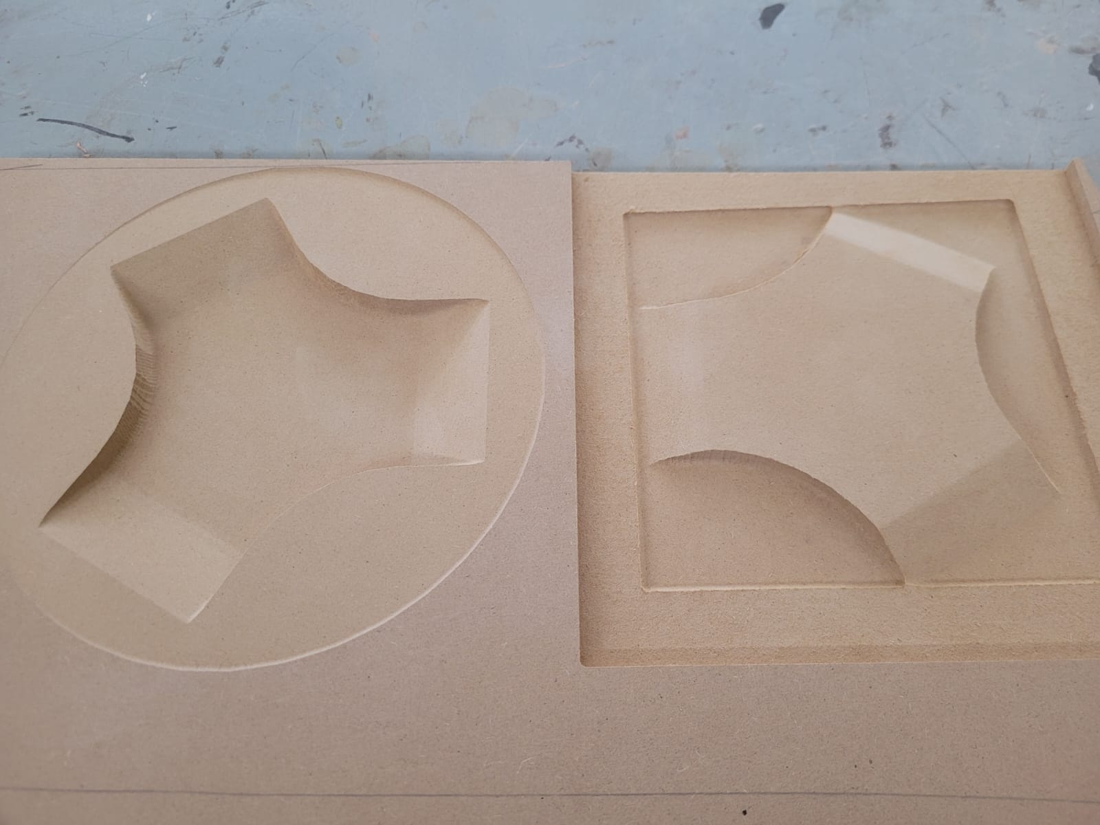
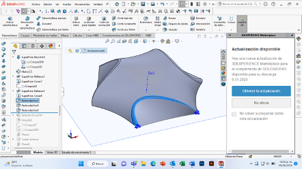
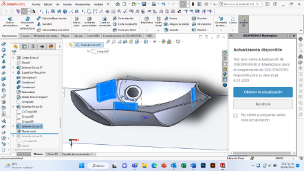
To carry out my thermoforming I needed a mold and a counter-mold, first I made my mold 1, I turned my solid piece into a flat surface, which I added a thickness of 20mm, to later substract that solid from a larger solid.
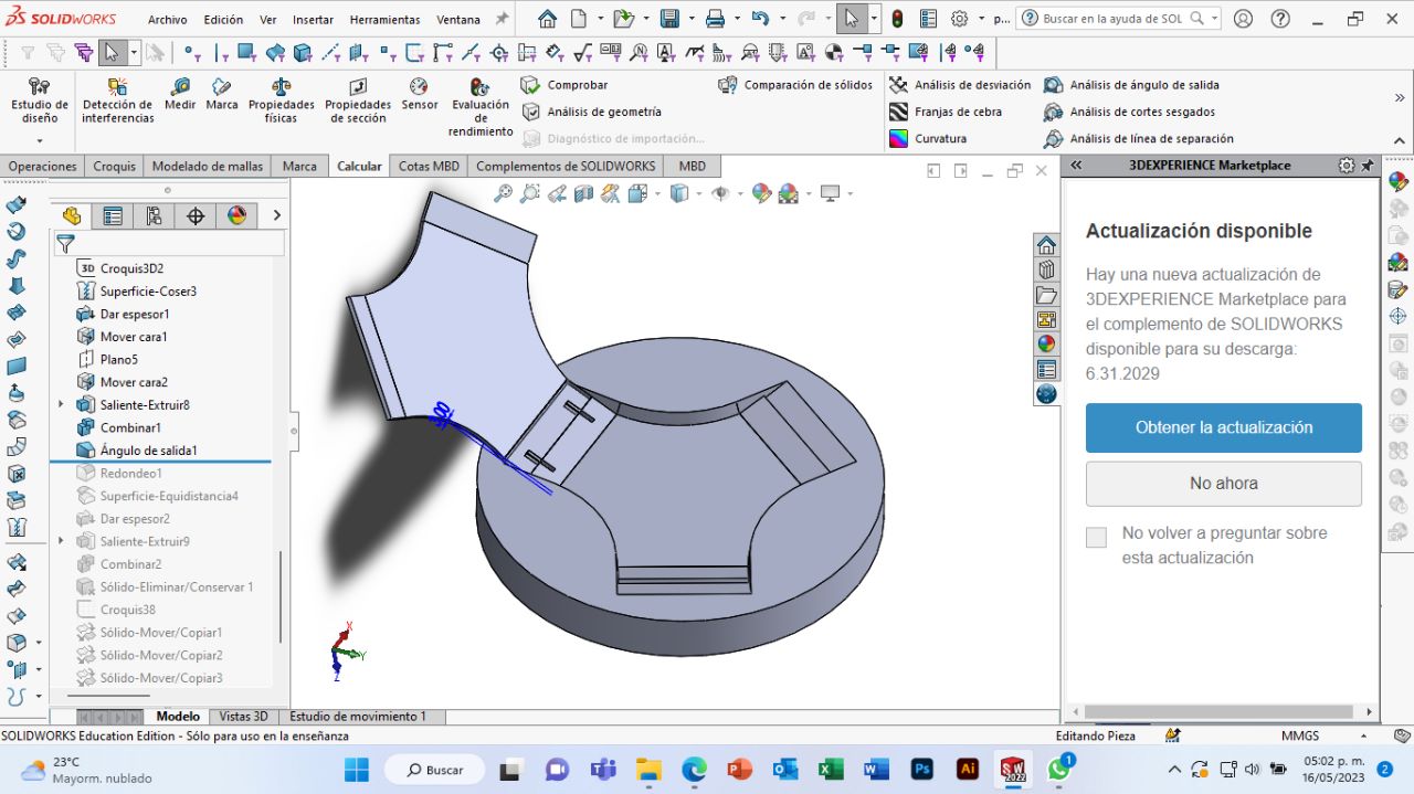
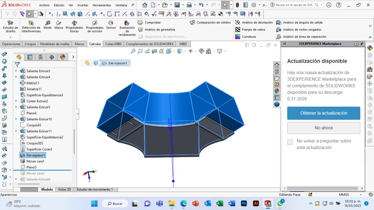
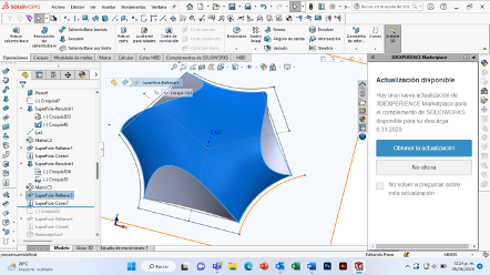
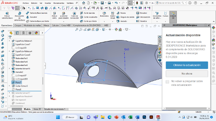
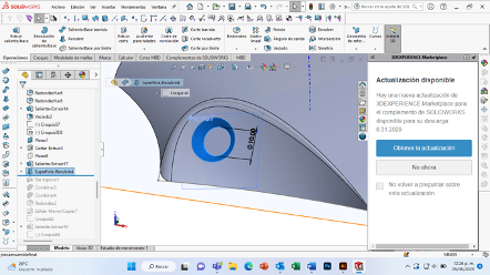
I did the same procedure as before, except that now the surface started from the other side of my module.


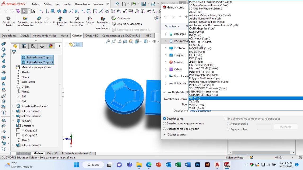
I saved my two molds in a single file as "stl" to later open it in the V Carve program.
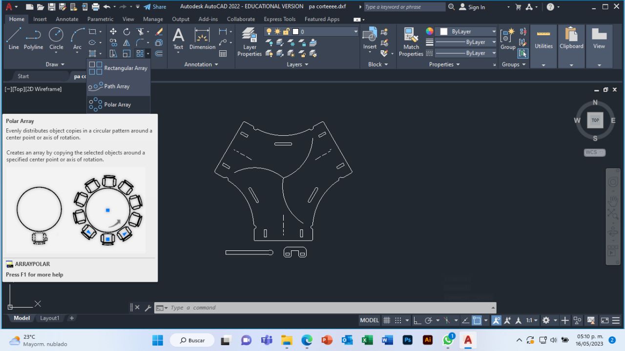
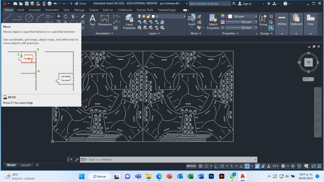
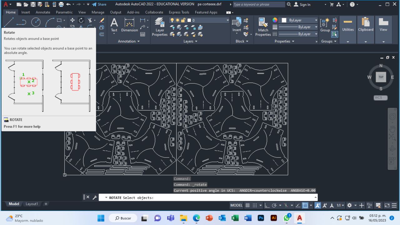
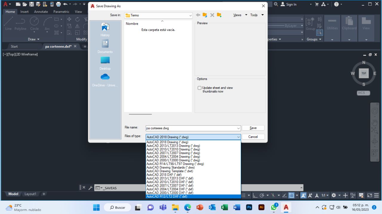
To check my cut file, I used the AutoCad program, I also made a design to engrave it and I arranged my pieces with the help of the "move" and "rotate" tools. Lastly I saved my file as AutoCadR12/LT2 DXF.
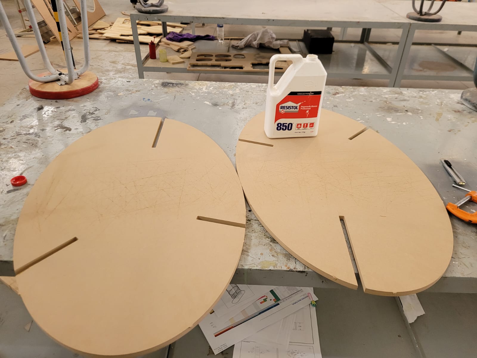
Before making the laser cut, I glued two 15mm MDF boards (it was waste from week 7). First I made some cuts and then glued it together and pressed my two boards together. Let the glue dry for 4 hours.


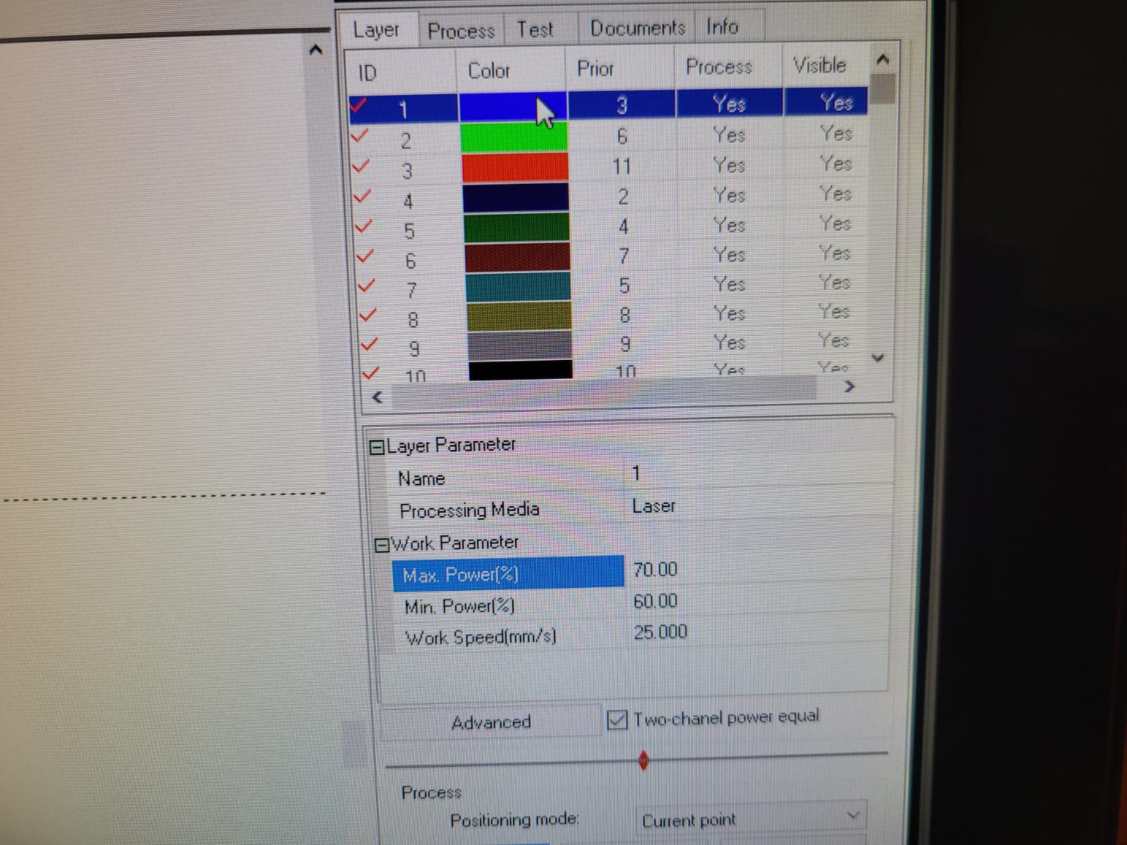
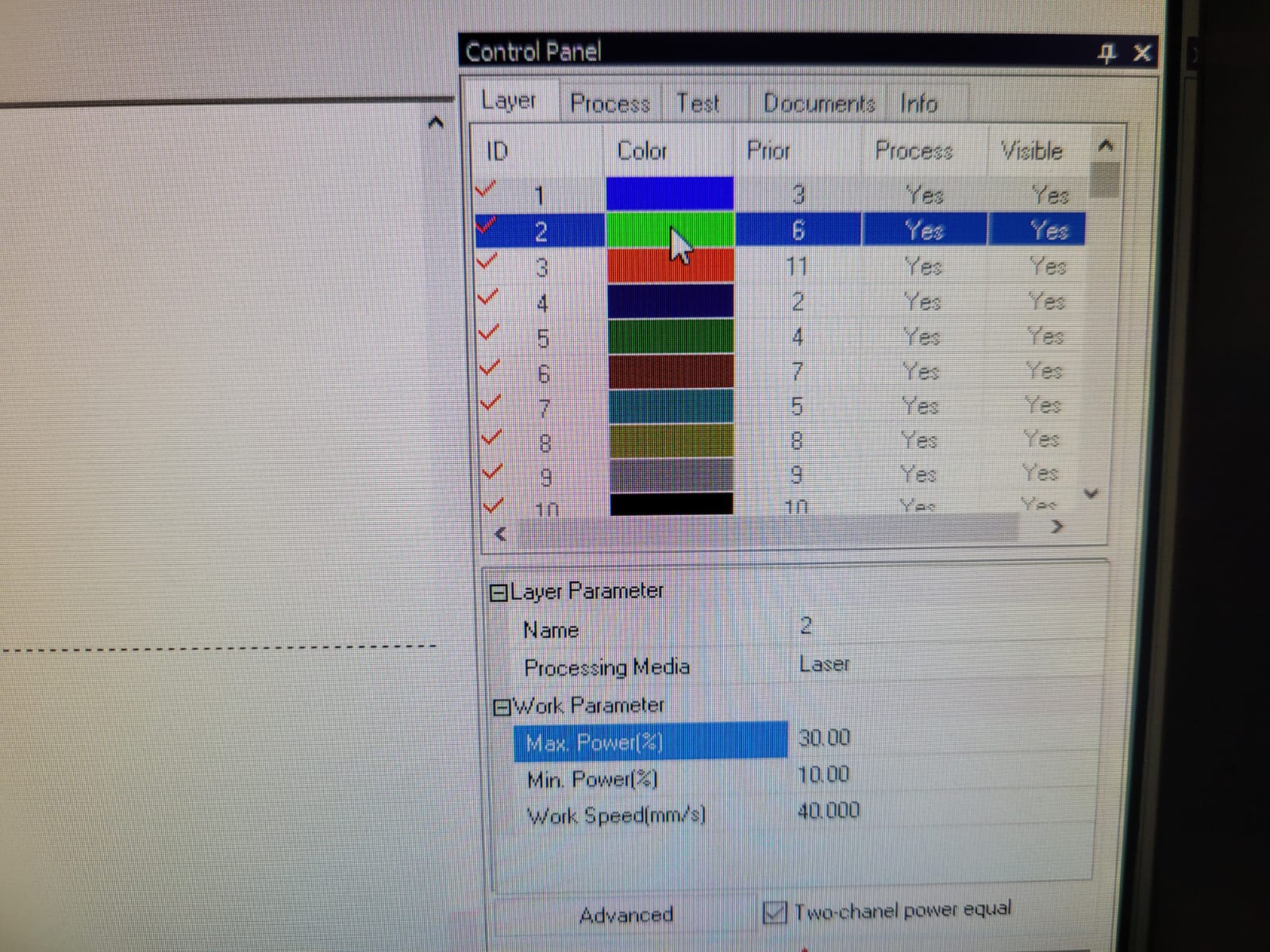
I did some tests to check the parameters for my cut, the images show the final parameters in which I cut my 3mm acrylic.
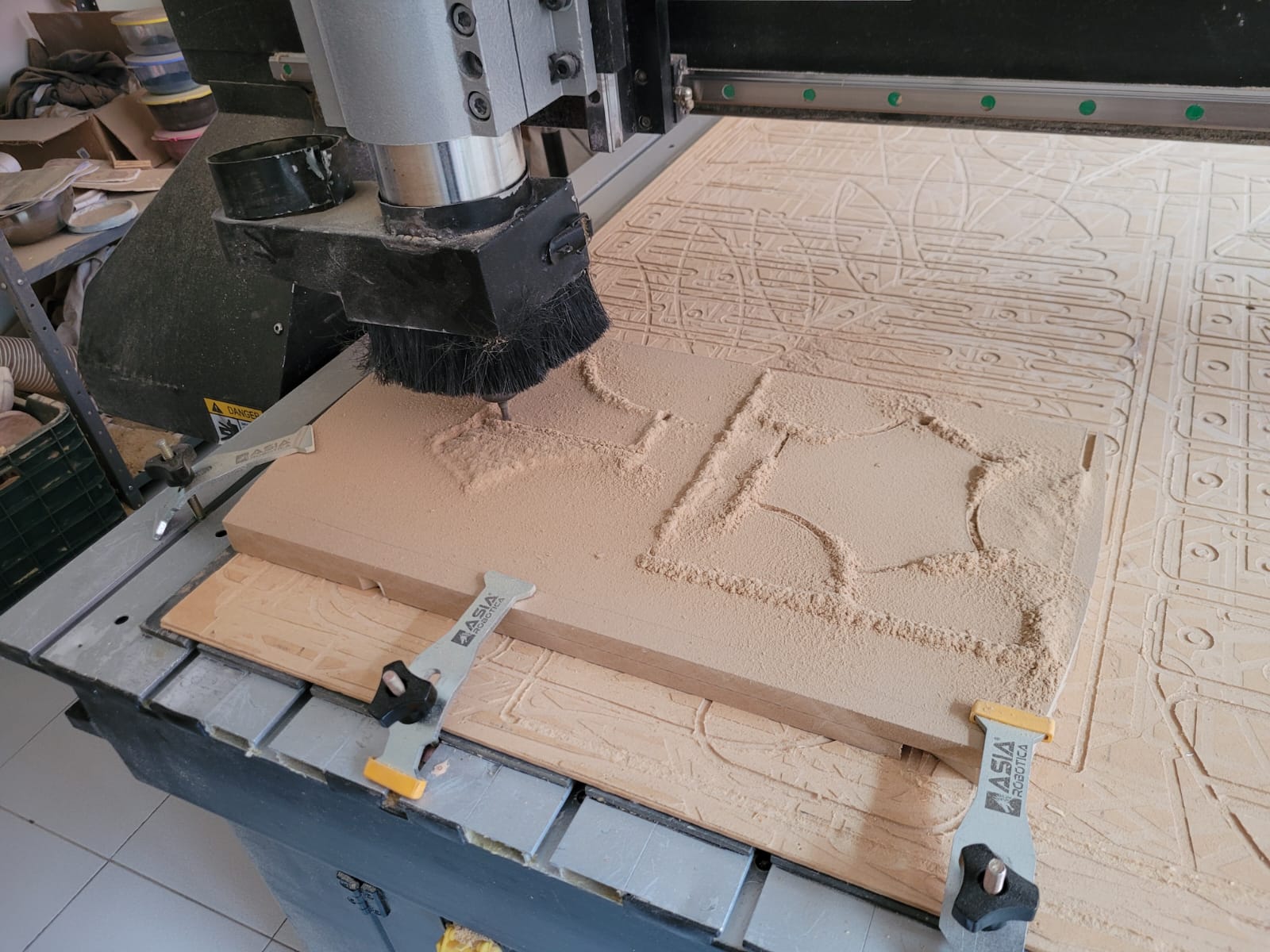
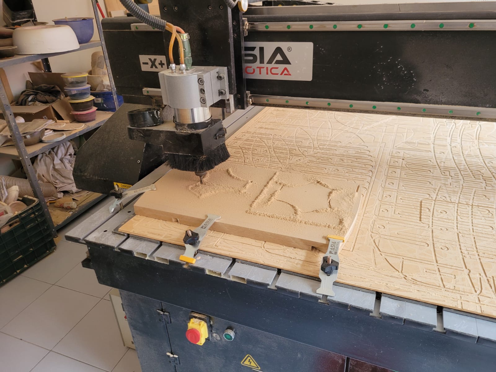
I make the G code with the V Carve program, with the parameters of week 12, make two files, one for roughing and the other for finishing.

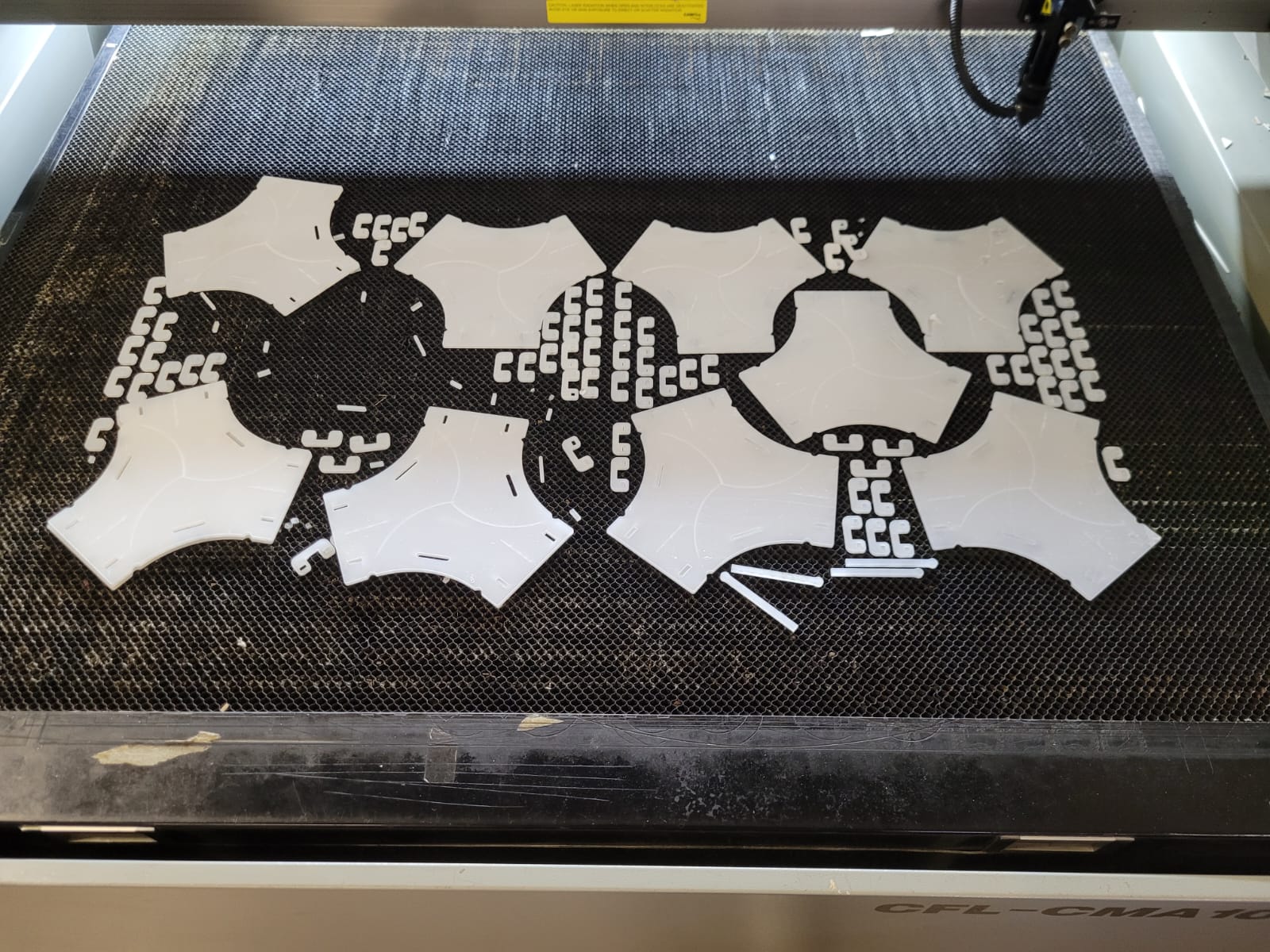
I did the roughing and finishing of my mold with the security measures, in the process it took me around 5 hours.
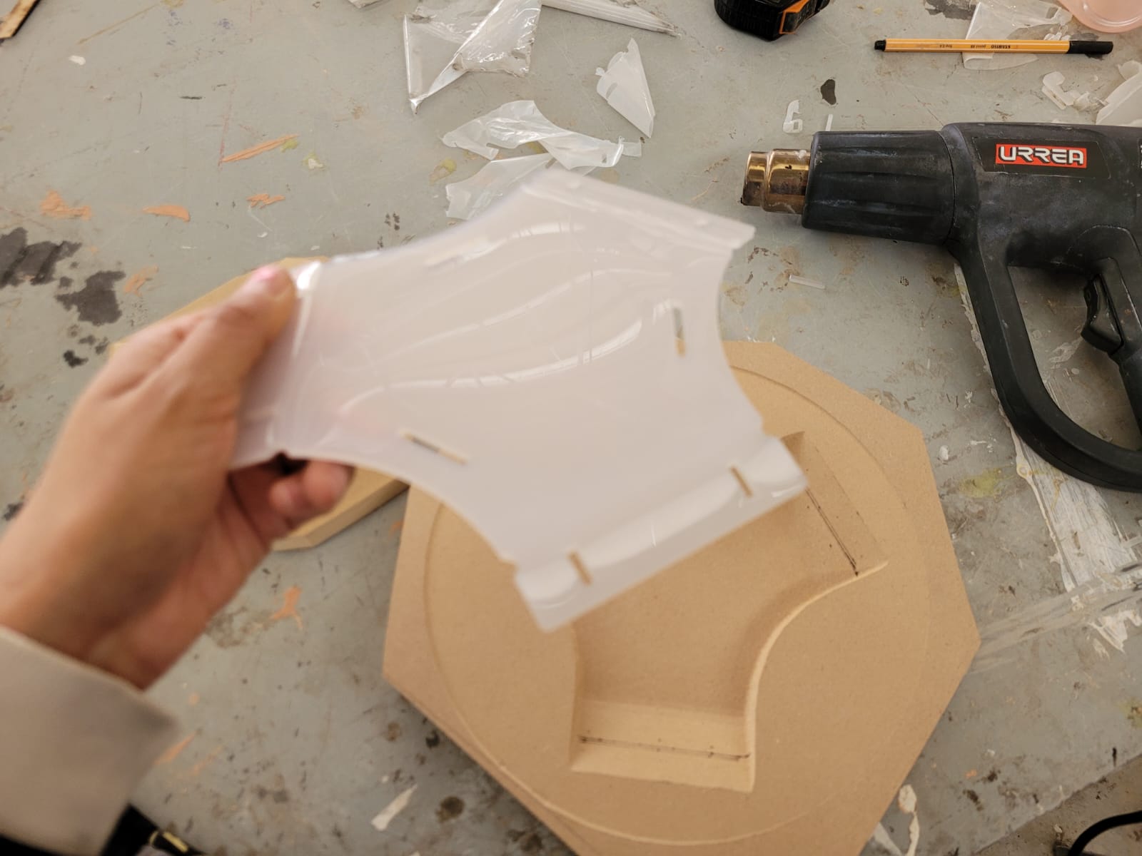
To begin with, it is necessary to wear gloves as a safety measure, it is also important to accommodate the piece.

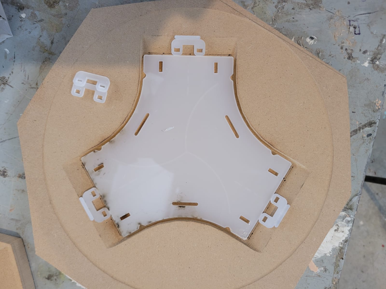
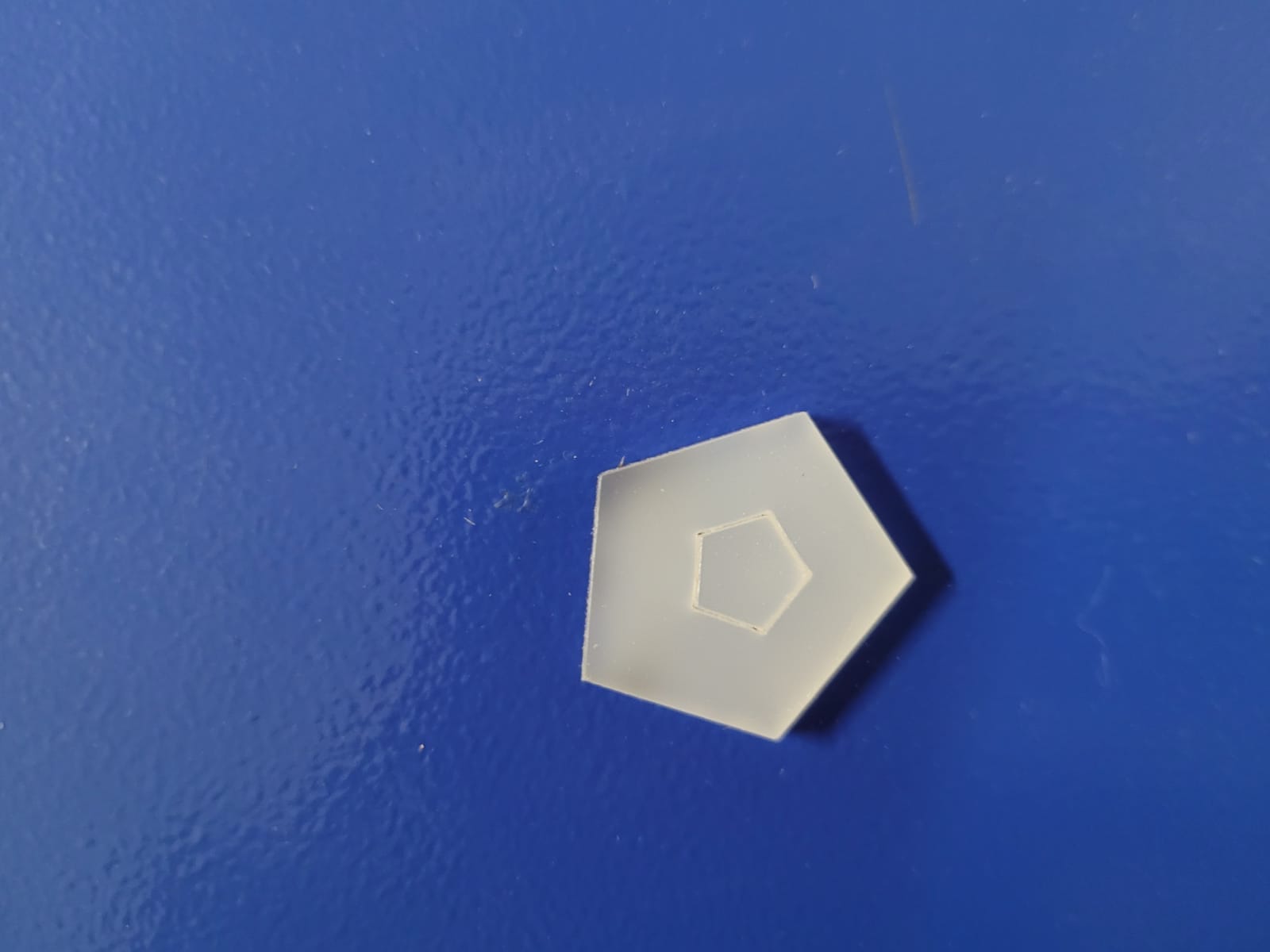
In this process, the acrylic piece is heated uniformly first, until it takes the shape of the mold for at least 40 seconds, then the counter-mold is placed for at least 5 min.
If the piece is warm can be cold with a pressured air.

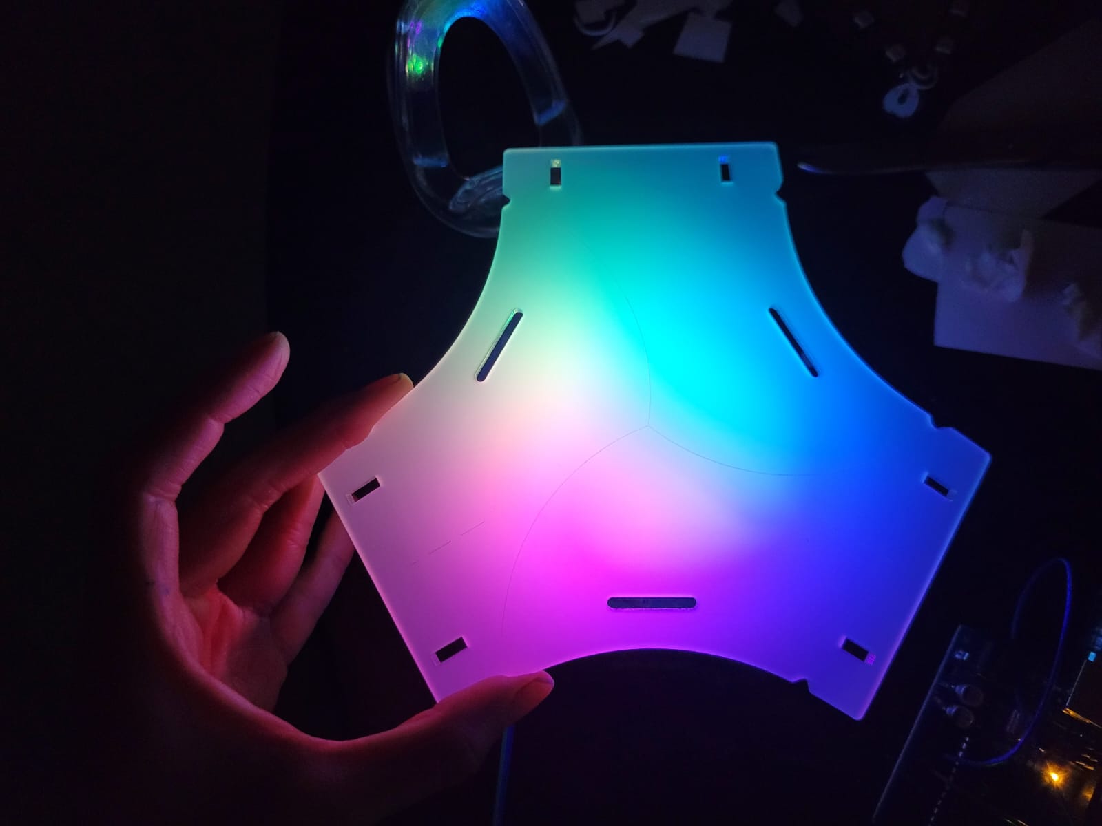
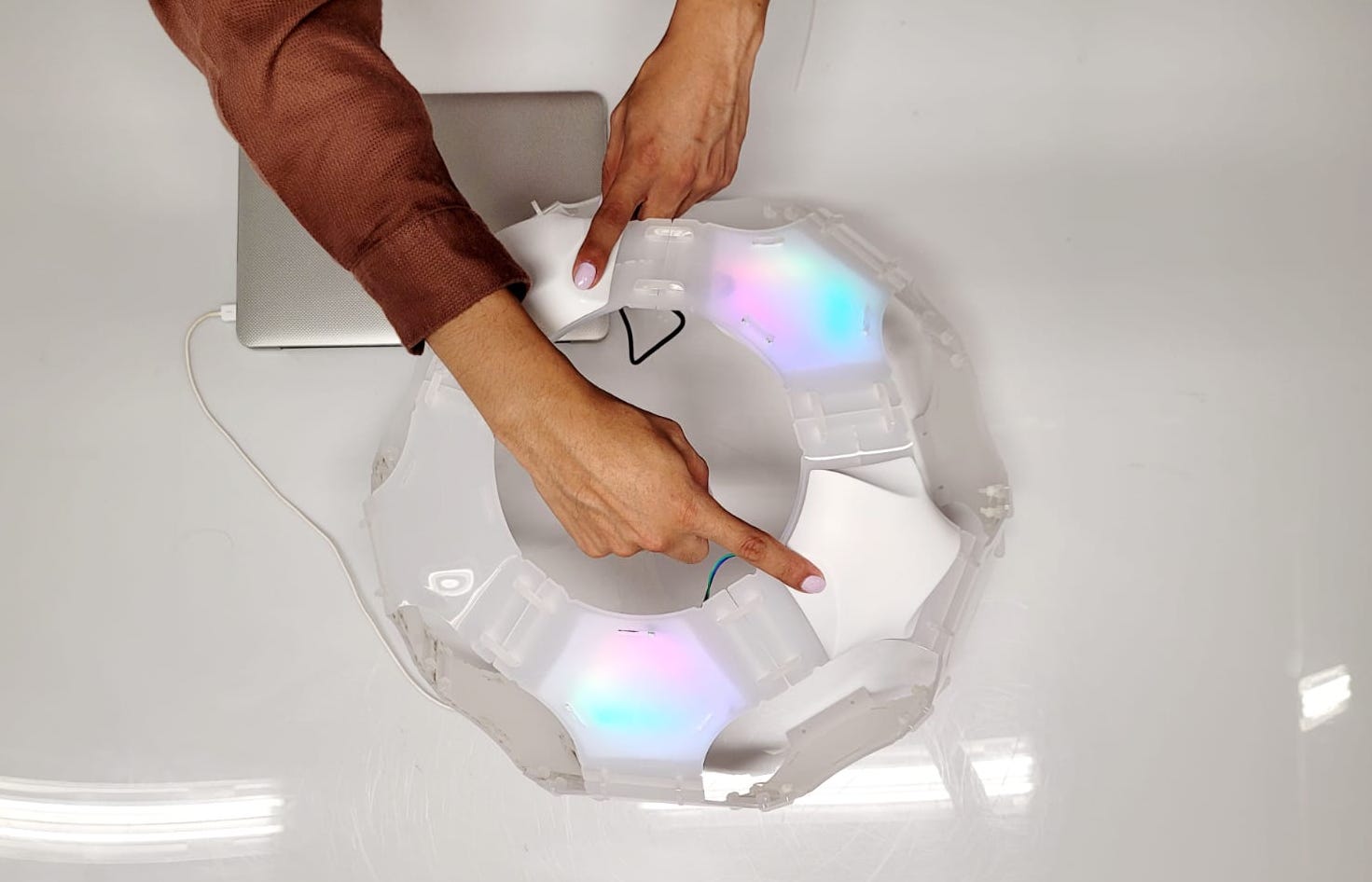
The module can be assembled in two different ways, one is flat, the circle is closed with 6 modules.
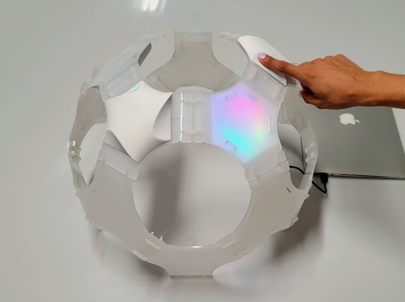
The other way of assembling is building a sphere, to close a circuit 5 modules are needed.
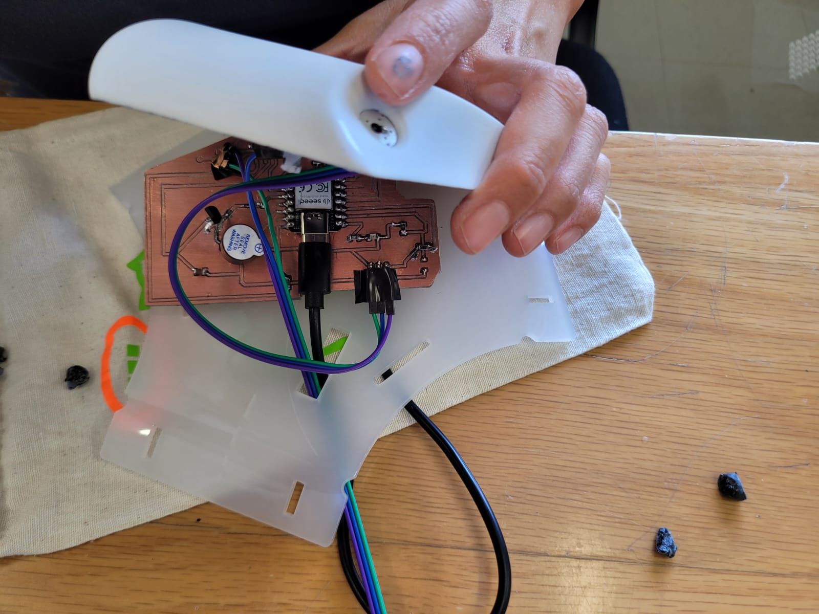
I used the schematic and the PCB board that I had designed and manufactured in my week 8, which I did before in my 6th week. This board is designed for a Xiao rp2040, with Hight Performance (Powered by Raspberry Pi 2040 chip, dual-core operating up to 133 MHz, equipped 264KB of SRAM, and 2MB of onboard flash memory), and Multiple Development Interfaces (2x buttons, 11x digital / 4x analog pins, 1x I2C interface, 1x UART port, 1x SPI port, and 1x SWD Bonding pad interface).


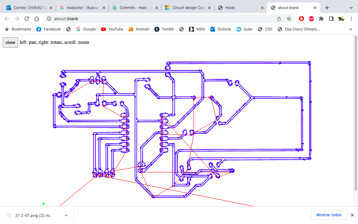
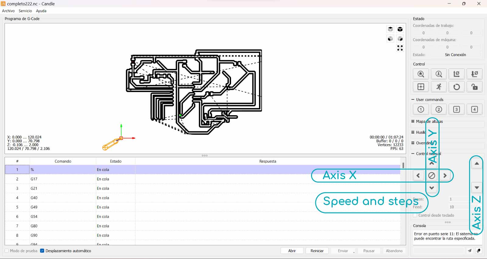
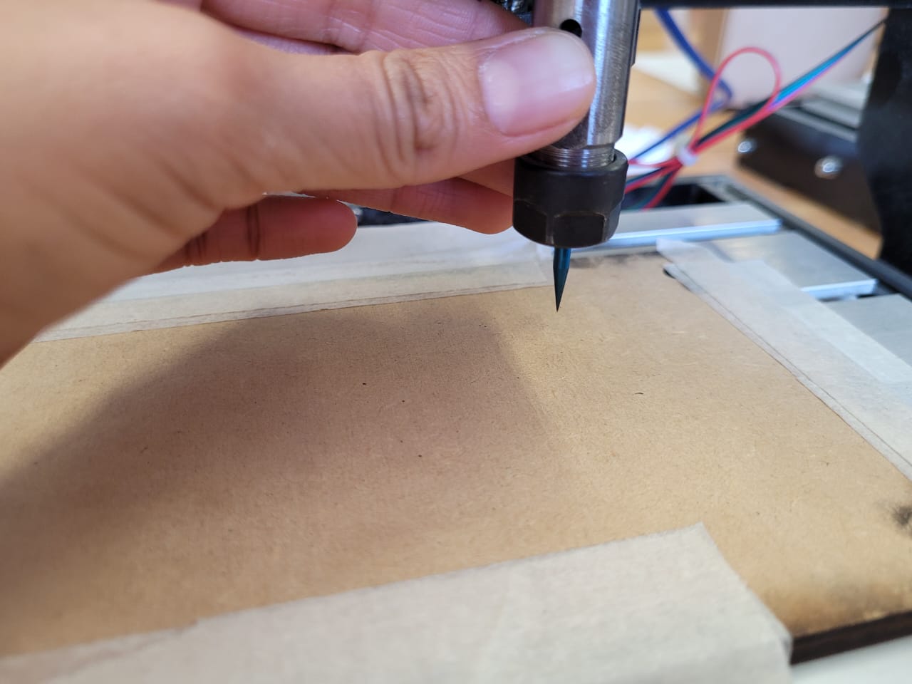
For the generation of the G code, I use MODS that is quite accessible and easy to use, in my week 8 I explain how to use this tool. The Candle program is very intuitive and will help you make this cut on your CNC machine.


I used the list that I generated in week 6, and I gathered the components to solder them one by one, I will leave the largest components at the end except the xiao to check their space on the pcb.
| Part Value | Device | Package | Description |
|---|---|---|---|
| C1 0.1UF | C_CHIP-1206(3216-METRIC) | CAPC3216X135 | Capacitor - Generic |
| C5 0.1UF | C_CHIP-1206(3216-METRIC) | CAPC3216X135 | Capacitor - Generic |
| D2 1655 | 1655 | LED_1655 | Ws2812b 5050 Rgb Led / Adafruit Industries 1.6 mm |
| D3 1655 | 1655 | LED_1655 | Ws2812b 5050 Rgb Led / Adafruit Industries 1.6 mm |
| D4 LED_RED | CHIP-FLAT-G_1206 | LEDC3216X75N_FLAT-G | RED |
| JP1 PINHD-1X3/90 | PINHD-1X3/90 | 1X03/90 | PIN HEADER |
| JP2 PINHD-1X1 | PINHD-1X1 | 1X01 | PIN HEADER |
| JP3 PINHD-1X4/90 | PINHD-1X4/90 | 1X04/90 | PIN HEADER |
| JP4 PINHD-1X2/90 | PINHD-1X2/90 | 1X02/90 | PIN HEADER |
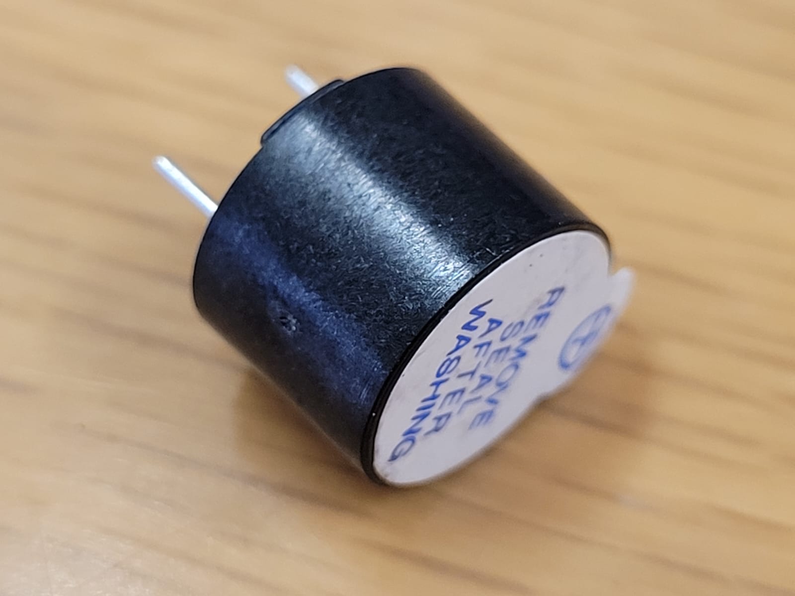
| LS1 AI-1223-TWT-12V-R | AI-1223-TWT-12V-R | XDCR_AI-1223-TWT-12V-R | BUZZER |
| Q2 NPN | NPN_SOT23-BEC | SOT95P237X112-3N | NPN - Generic TRANSISTOR |
| R1 R-US_CHIP-1206(3216-METRIC) | RESC3216X70 | - | Resistor Fixed - ANSI |
| R2 1001 R-US_CHIP-1206(3216-METRIC) | RESC3216X70 | - | Resistor Fixed - ANSI |
| R3 3000 R-US_CHIP-1206(3216-METRIC) | RESC3216X70 | - | Resistor Fixed - ANSI |
| R4 000 R-US_CHIP-1206(3216-METRIC) | RESC3216X70 | - | Resistor Fixed - ANSI |
| R5 000 R-US_CHIP-1206(3216-METRIC) | RESC3216X70 | - | Resistor Fixed - ANSI |
| S1 B3U-3000P(M)-B | B3U-X000B3U3000P(M)-B3000P(M)-B B3U-3000P(M)-B | - | Ultra-small Tactile Switch |
| U2 XIAO-THRUHOLEHYBRID-SMT-THT | XIAO-THRUHOLEHYBRID-SMT-THT | XIAO-GENERIC-HYBRID-MODULE14P-2.54-21X17.8MM | Seeed Studio XIAO Series Through-hole |
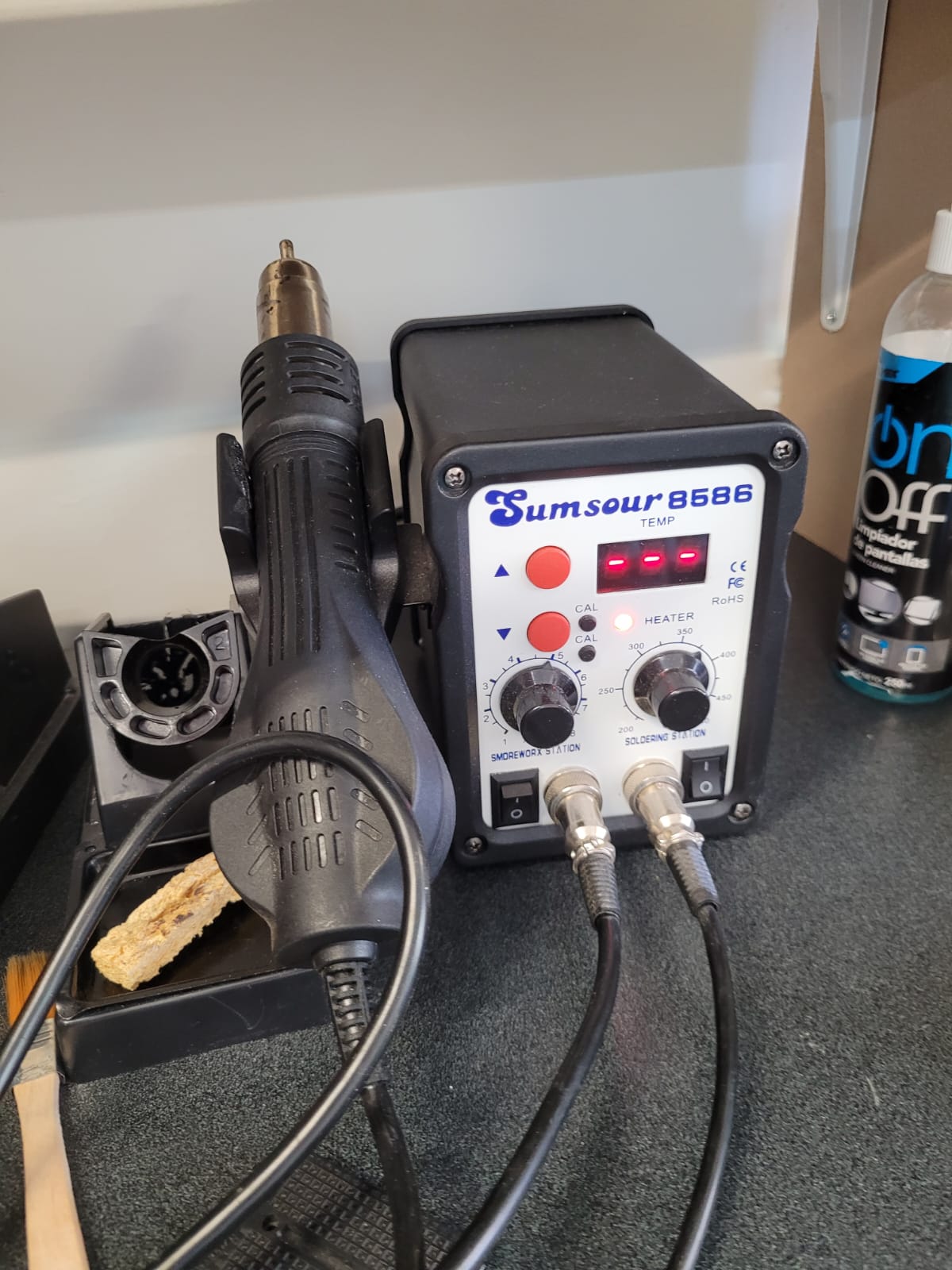
To start soldering, select my components and use a soldering station.
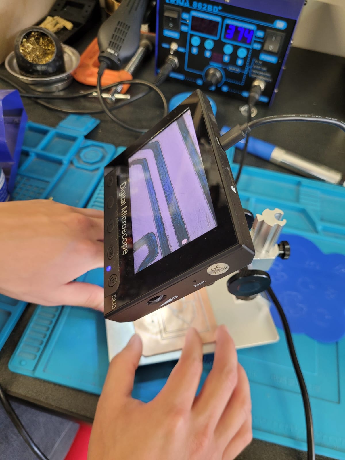
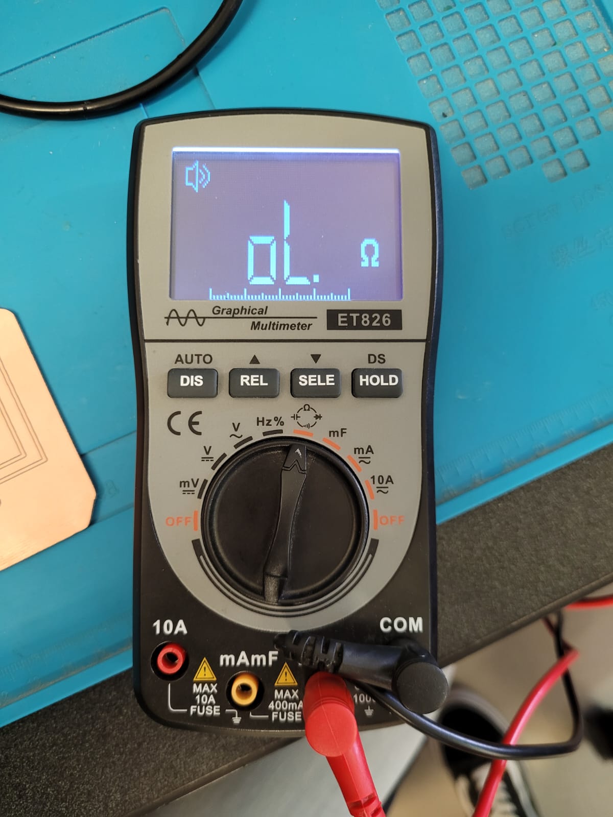
The multimeter helped me verify that there were no crosses and the digital microscope helped me verify where I could have excess solder.

It was easier for me to place the soldering first and then the components, these were very small and I did not have much experience, but I placed them calmly.
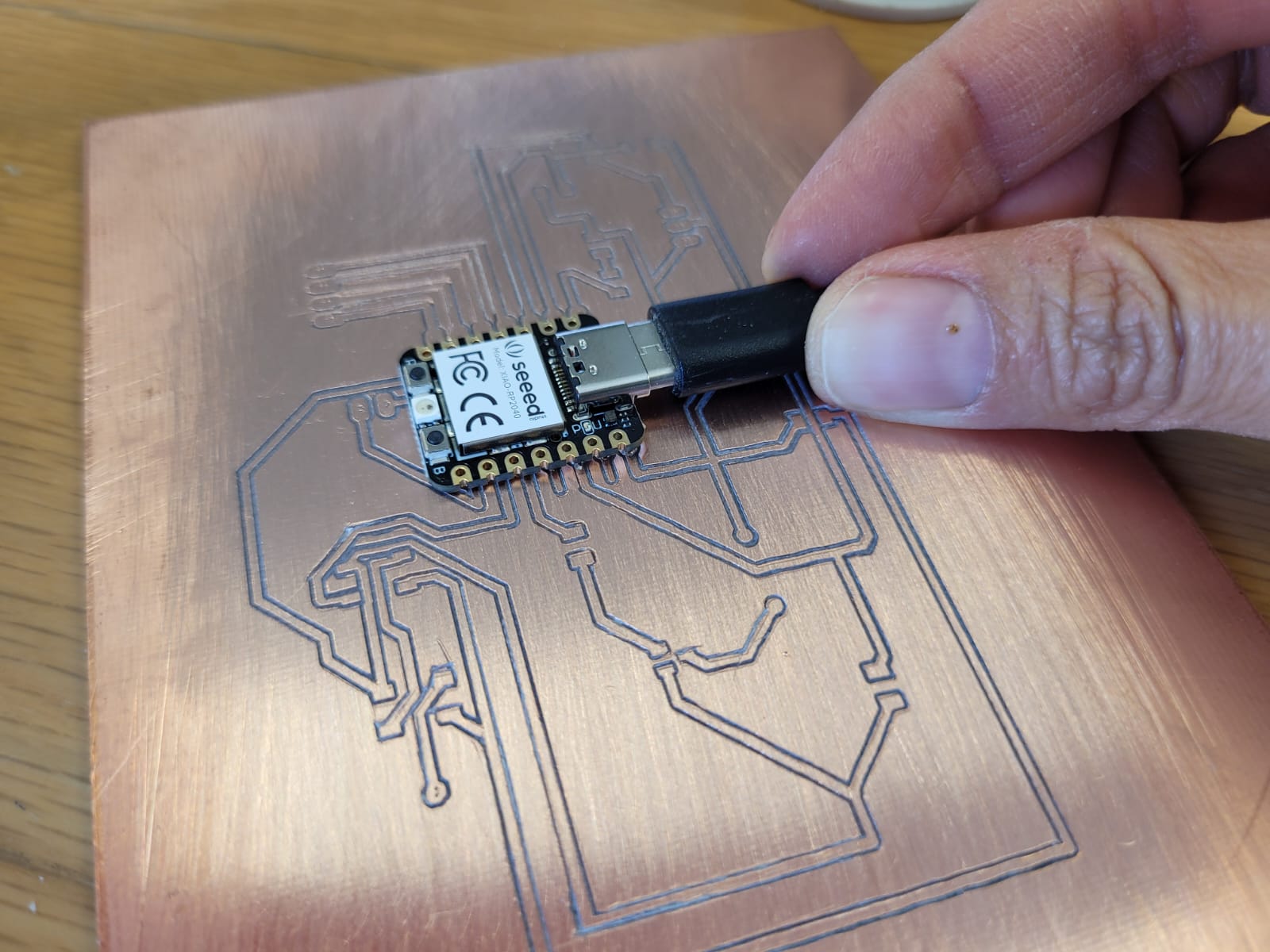

It was quite difficult and I appreciate that my instructor told me to do the thick lines.


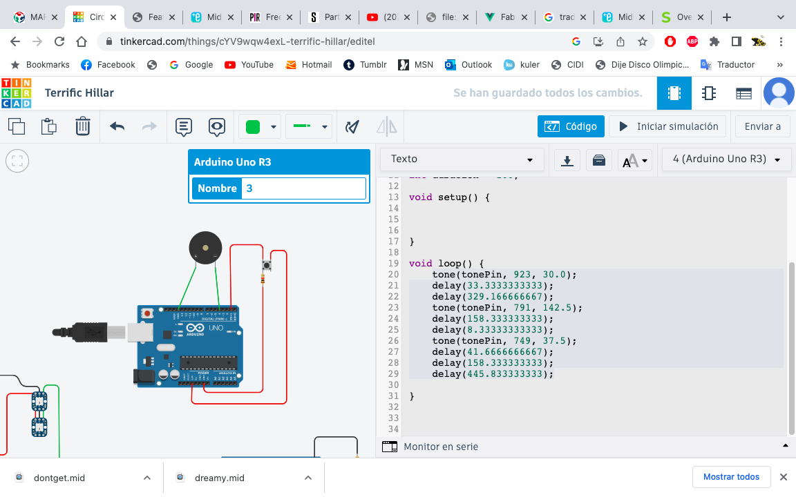
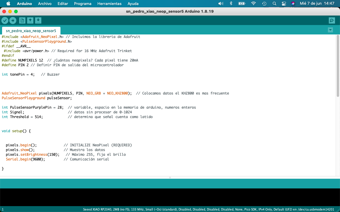
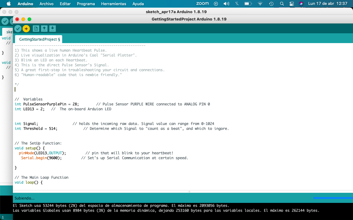
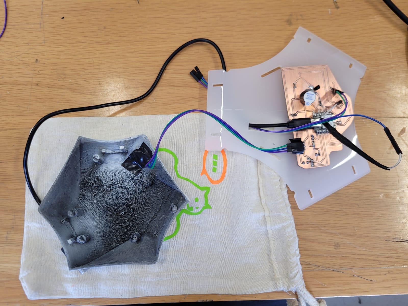
When using my PCB layout, I only concentrated on the pins where I would have my programming, for my Neopixels I used Pin 2, for my buzzer Pin 4 and for my sensor Pin 28.
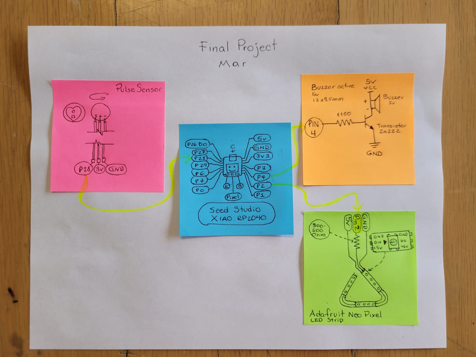
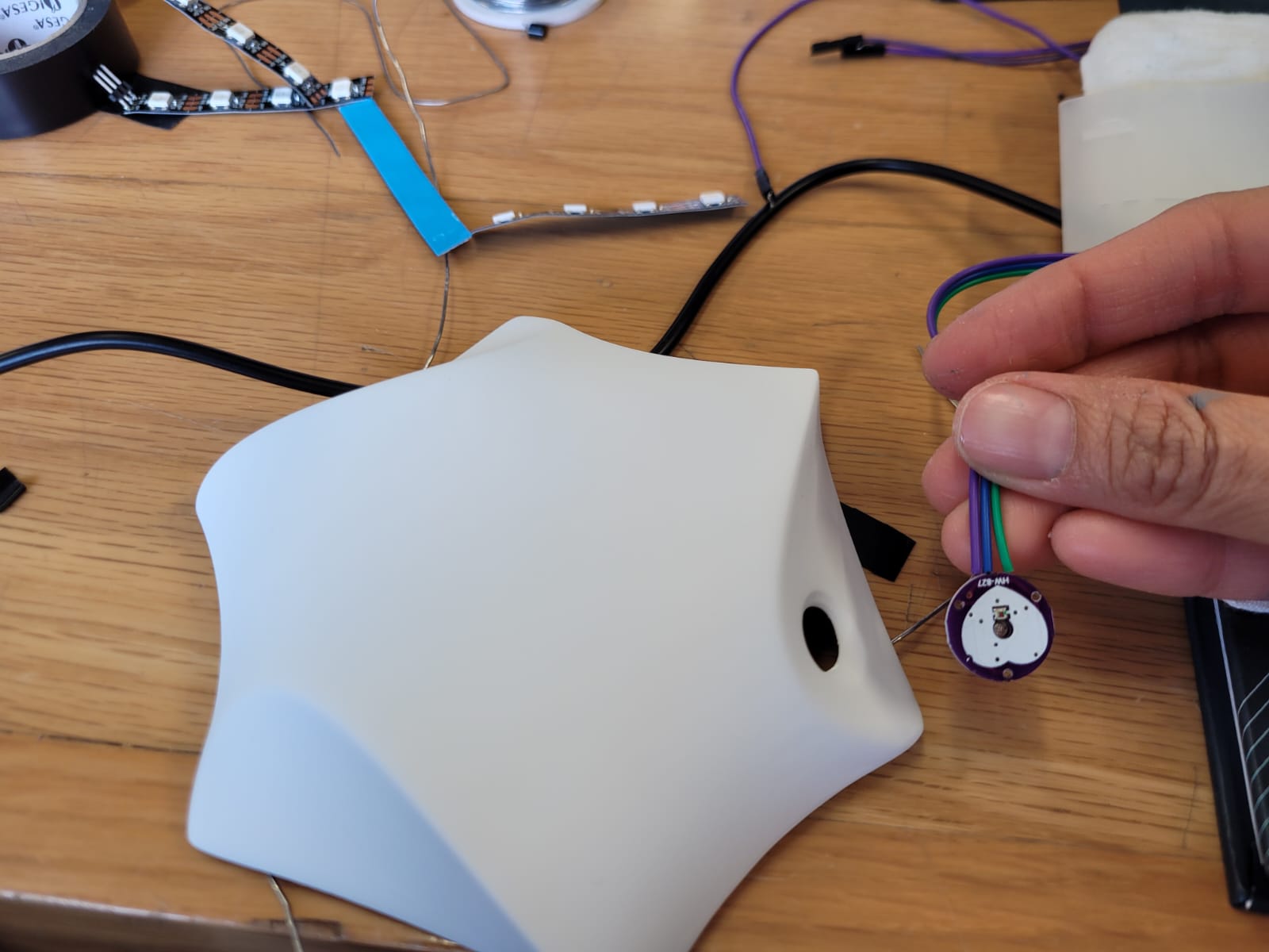
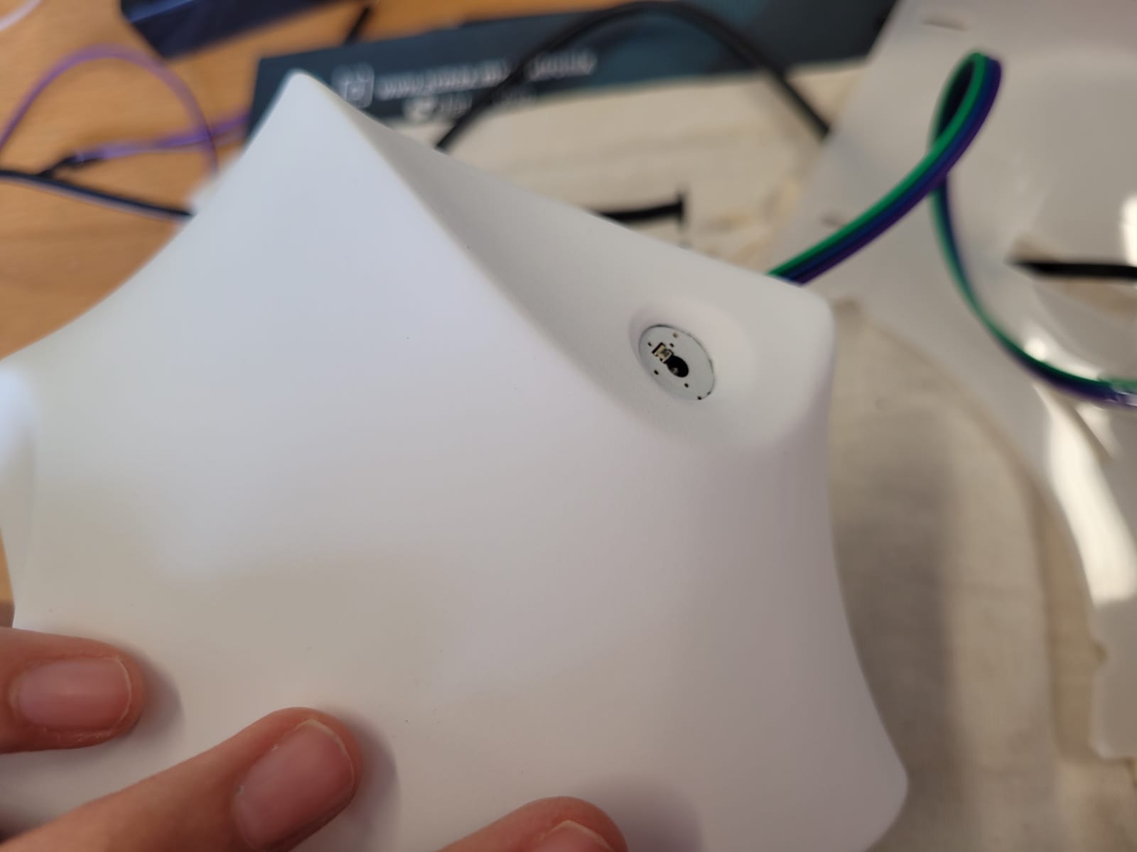
This sensor measures the heart rate, it is used to easily incorporate data into any project. The current consumption is low, being 4mA with a 5v supply. It is build with a emitting LED and also a intensity receiving sensor. The amount of light reflected by the finger bloodstream defines the output of the sensor, and it is possible to recover data from it.
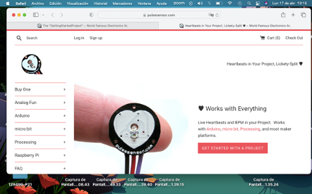
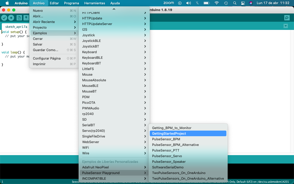
On the provider's website you can find tutorials on how to install the library and "examples" with different tasks to use in Arduino.
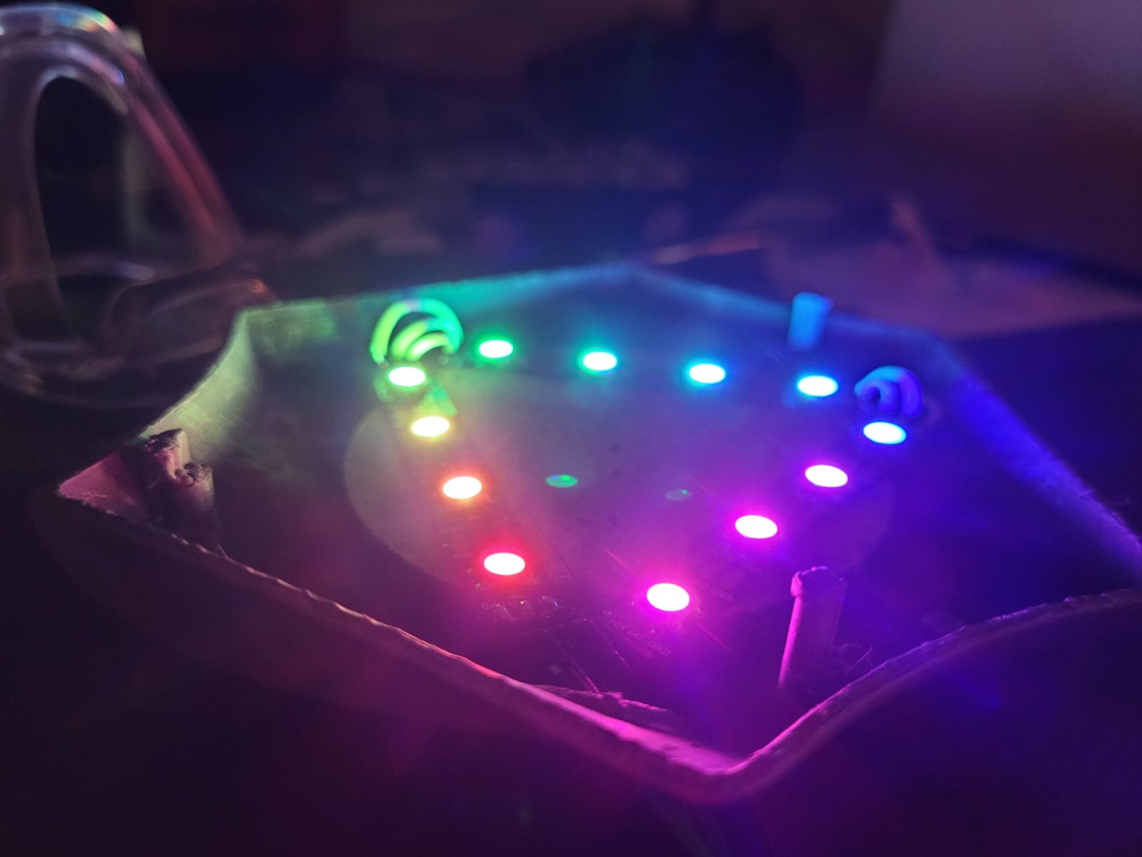
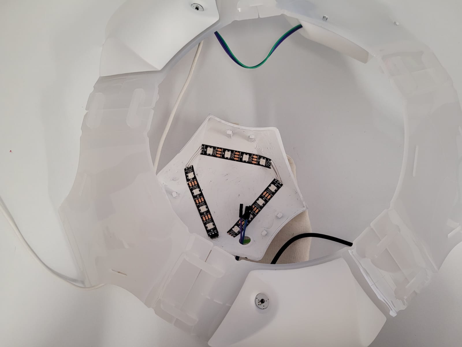
For the Neopixels, I wanted to form a triangle with the lights, so I bought a NeoPixel strip from Adafruit, the triangle was made up of 4 neopixels per side, having a total of 12 neopixels. For these 12 neopixels, the following is taken into account: 20mA (consumption for each led) is multiplied by 3 (because they are the leds that each Neopixel, GRB contains), this is multiplied by the number of Neopixels and gives a total of 720 mA that my triangle of neopixels will consume, it is important to take it into account because my microcontroller has more, otherwise an external source must be used.
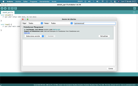
This library have many "examples" for uses with the sensor. At this point i just used the "Getting Started Proyect" code. To experiment with it, i use an Arduino PCB and i put in place the indicated pines.

I follow the provider tutorials to make the first activation code from a blue led connected to an arduino plate.
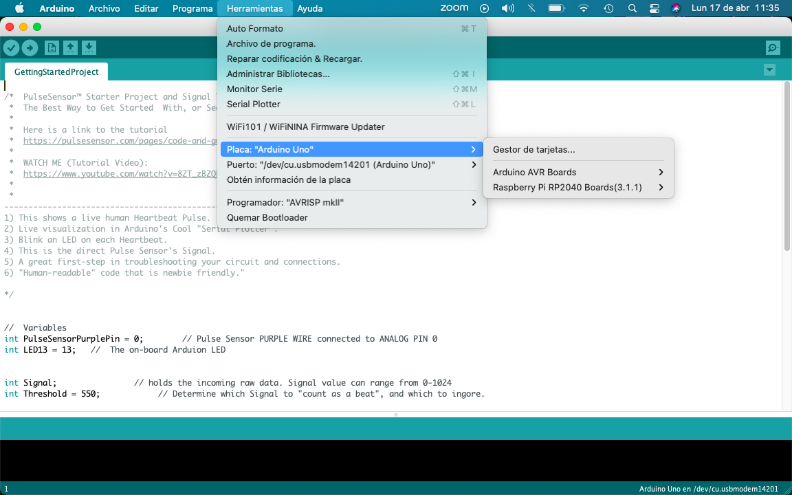
I started my programming on the Xiao microcontroller. Tools-> Board-> Boards Manager. Then i select the lastest version of "Raspberry Pi Pico/RP2040"; And finally i just needed to select the port. After this, i modified the code to play it with my PCB schematics.

For the Neopixels, I wanted to form a triangle with the lights, so I bought a NeoPixel strip from Adafruit, the triangle was made up of 4 neopixels per side, having a total of 12 neopixels. For these 12 neopixels, the following is taken into account: 20mA (Consumption for each led) is multiplied by 3 (because they are the leds that each Neopixel, GRB) contains, this is multiplied by the number of Neopixels and gives a total of 720 that will consume my triangle of neopixels (I use a 500 Ohm resistor) is important to take into account because my microcontroller is larger, otherwise an external source must be used.
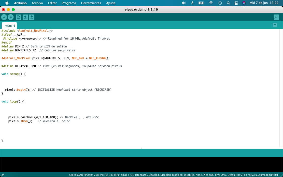
Previously I had already installed the Adafruit library to use the neopixels, I started with a program where the leds were illuminated with the "rainbow" command, this assigns the present neopixels a different color from the chromatic circle.
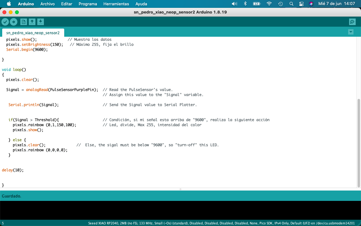
At this point, I carried out multiple actions to reach the conclusion of continuing with the structure that I already had for my sensor to now integrate it with my Neopixels, taking into account the codes to show and turn off the neopixels.
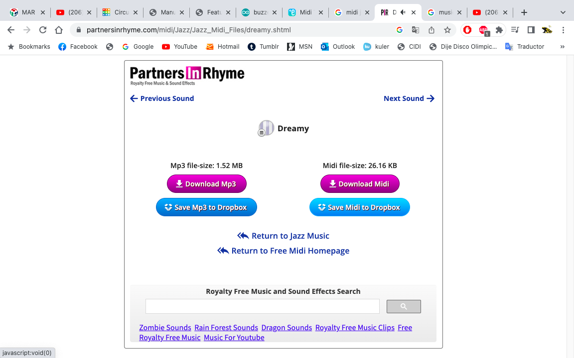
For the Buzzer, I first had to convert a tune into the "tone" language that the Arduino has. First, put the music that interested me in the search engine and add the term “Jazz Chill”.
Then I downloaded the melody I liked and on the “Midi to Arduinno” website and uploaded the melody to convert it to the tones I wanted.“Midi”.
From the website I took the melodies that I liked the most and changed the frequency to make it sound better, to integrate them into the structure of my code in Arduinno.


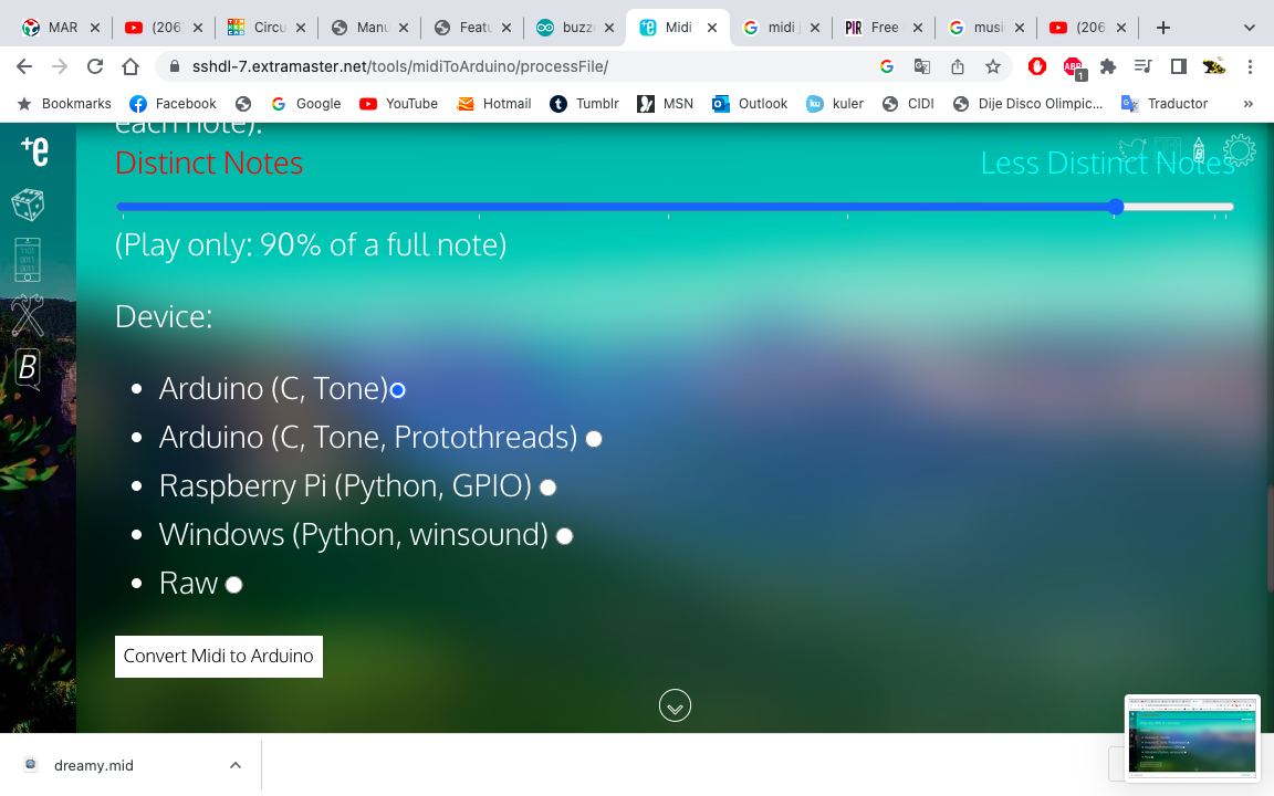
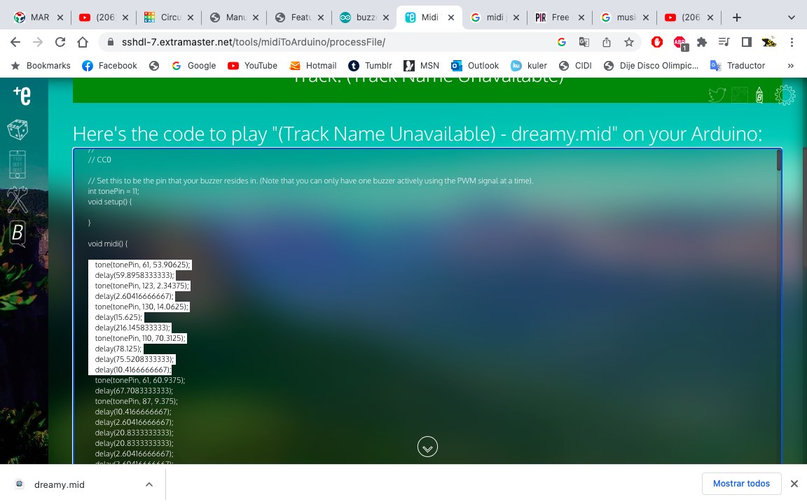
From the website I took the melodies that I liked the most and I played with the frequency in Tinkercad, then I passed the tones to the structure of my code in Arduino.
            #include Adafruit_NeoPixel.h // Incluimos la librería de Adafruit,Add <>
            #include
            #ifdef __AVR__
             #include avr/power.h // Required for 16 MHz Adafruit Trinket,Add <>
            #endif
            #define NUMPIXELS 12  // ¿Cuántos neopixels? Cada pixel tiene 20mA
            #define PIN 2 // Definir PIN de salida del microcontrolador

            int tonePin = 4;   // Buzzer


            Adafruit_NeoPixel pixels(NUMPIXELS, PIN, NEO_GRB + NEO_KHZ800);  // Colocamos datos el KHZ800 es mas frecuente
            PulseSensorPlayground pulseSensor;

            int PulseSensorPurplePin = 28;  // variable, espacio en la memoria de arduino, numeros enteros
            int Signal;                     // datos sin procesar de 0-1024
            int Threshold = 514;            // determina que señal cuenta como latido


            void setup() {


              pixels.begin();             // INITIALIZE NeoPixel (REQUIRED)
              pixels.show();              // Muestra los datos
              pixels.setBrightness(150);   // Máximo 255, fija el brillo
              Serial.begin(9600);         // Comunicación serial

            }

            void loop()
            {
              pixels.clear();

              Signal = analogRead(PulseSensorPurplePin);  // Leer el valor
                                                          // asignar a signal

               Serial.println(Signal);                    // Envía el valor de la señal a Serial Plotter.


               if(Signal > Threshold){                    // Condición, si mi señal esta arriba de "9600", realiza la siguiente acción
                 pixels.rainbow (0,1,150,100);            // primer led, primer pixel, división de la tira, saturación del color máximo 255, intensidad del color
                 pixels.show();                          // Actualiza y muestra el color
                 tone(tonePin, 923, 30.0);
                 delay(33.3333333333);
                 delay(329.166666667);
                 tone(tonePin, 791, 142.5);
                 delay(158.333333333);
                 delay(8.33333333333);
                 tone(tonePin, 749, 37.5);
                 delay(41.6666666667);
                 delay(158.333333333);
                 delay(445.833333333);


               } else {
                 pixels.clear();
                 pixels.rainbow (0,0,0,0);            // primer led, primer pixel, división de la tira, saturación del color máximo 255, intensidad del color
                 pixels.show();                              //  Else, the sigal must be below "9600", so "turn-off" this LED.
               }


            delay(10);


            }
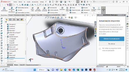
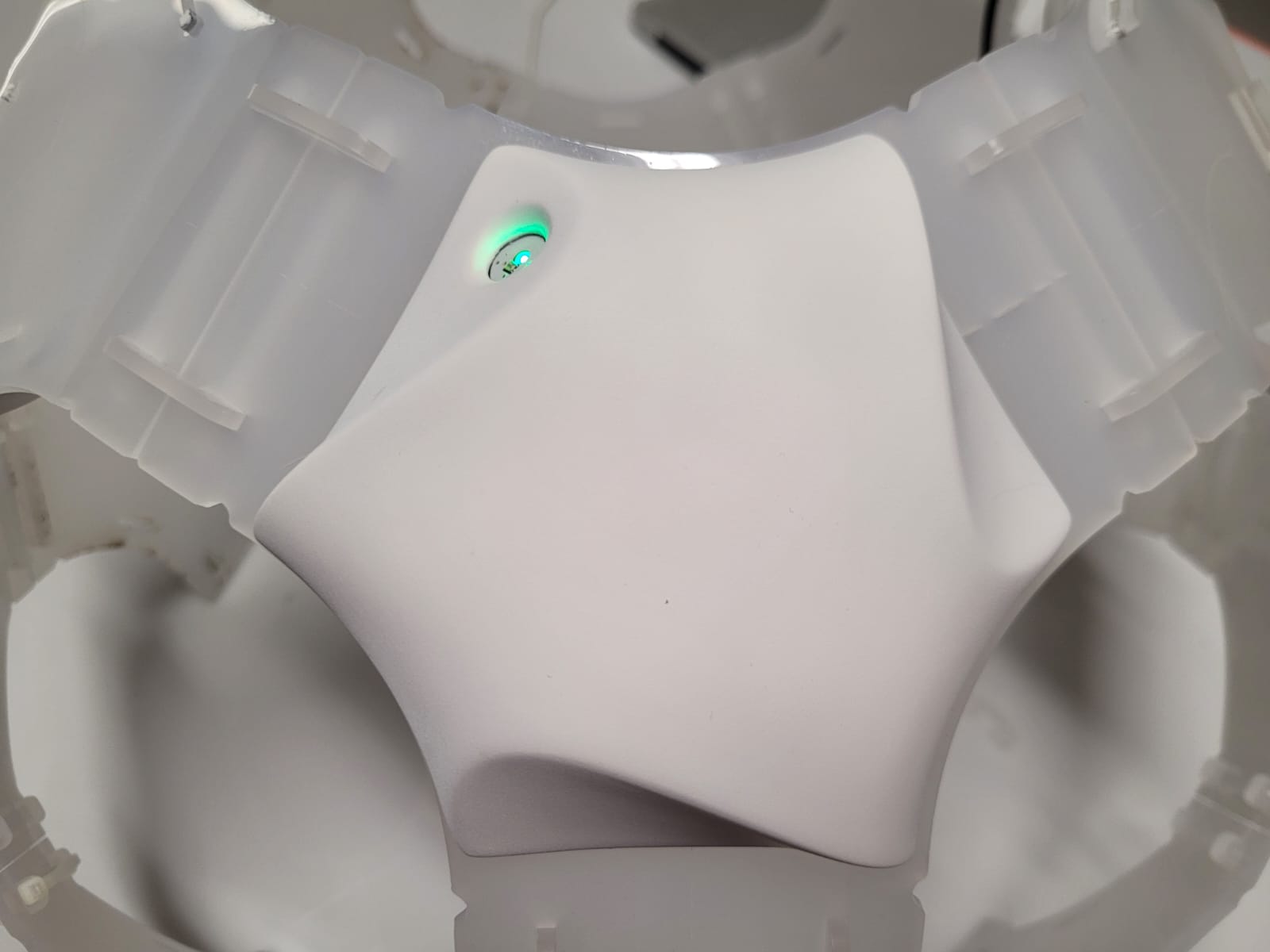
To protect my electrical components, I designed a casing in solid works, with the tools to "cover", "thicken", "fire", "round", "extrude" and "split". This case has the dimensions of my PCB that I had previously made.
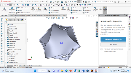

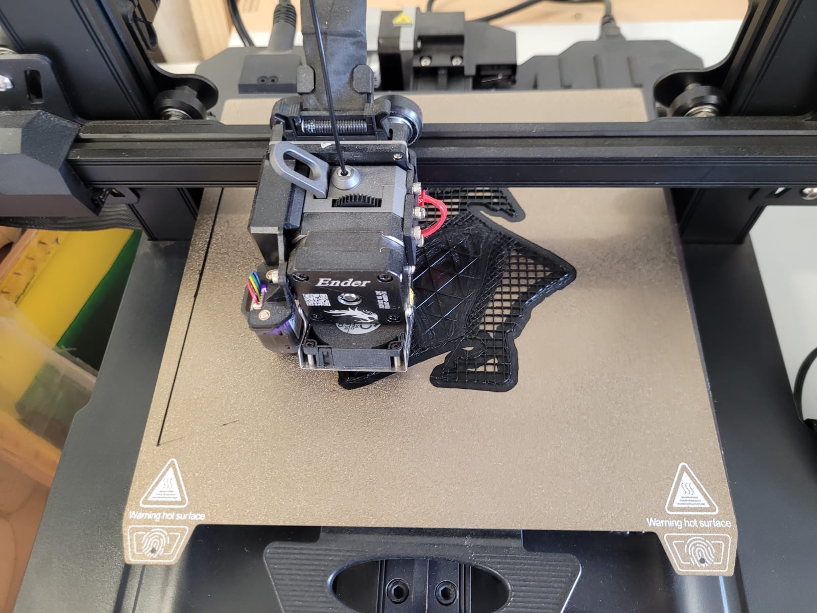
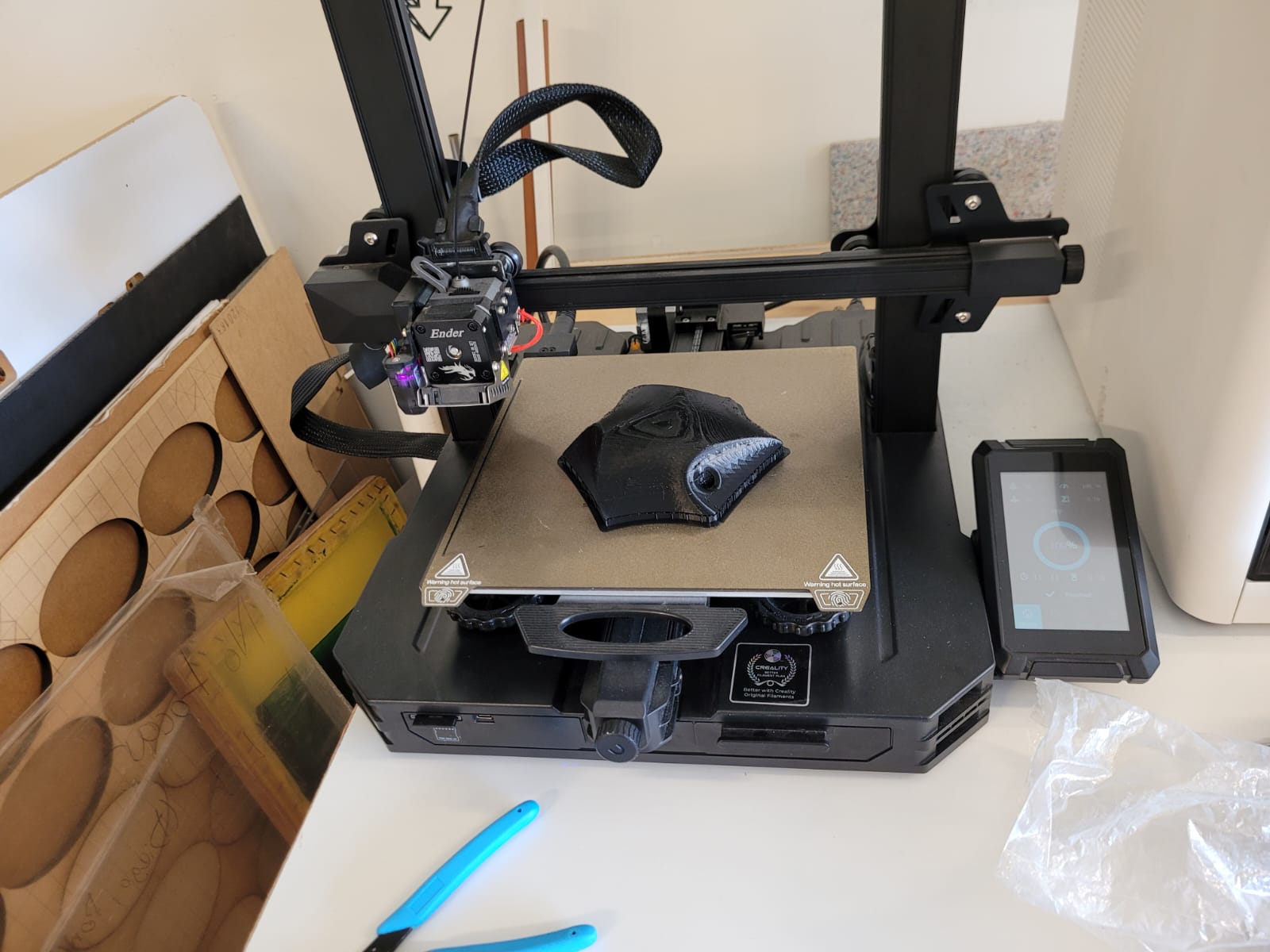
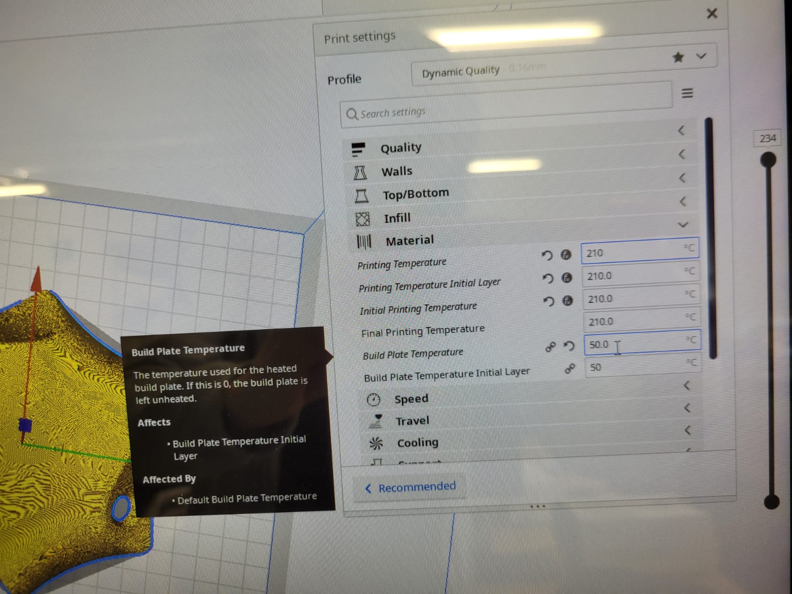
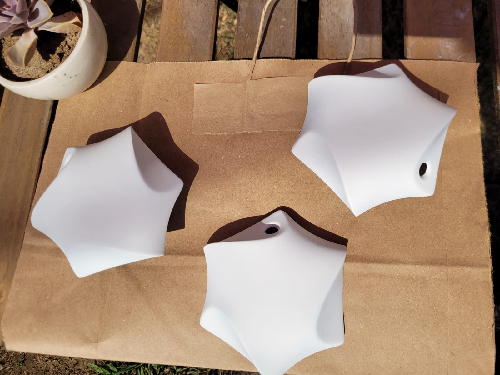
First I made 2 3D prints with the most visual part up, it took me 6 hours because of the support, because I wanted it to come out the same as the virtual one. I also printed two more with the open side up, it took less time but it didn't look as good as the first prints.
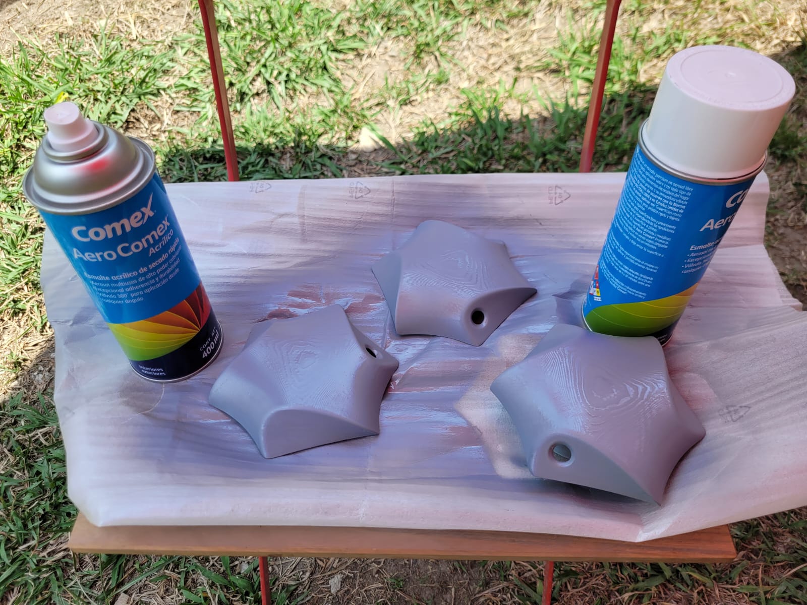
After this I sanded my shells with water sandpaper and then painted them, first with a primer and then with a matt white spray paint.


To build my structure, I first decided to make the sphere, as I was placing the components I realized that I was missing a hole in the back, so I cut a hole in the laser machine for my cables in the modules where I would have my neopixels.
Make two modules with the heart rate sensor and then place the modules where the neopixels would be seen.

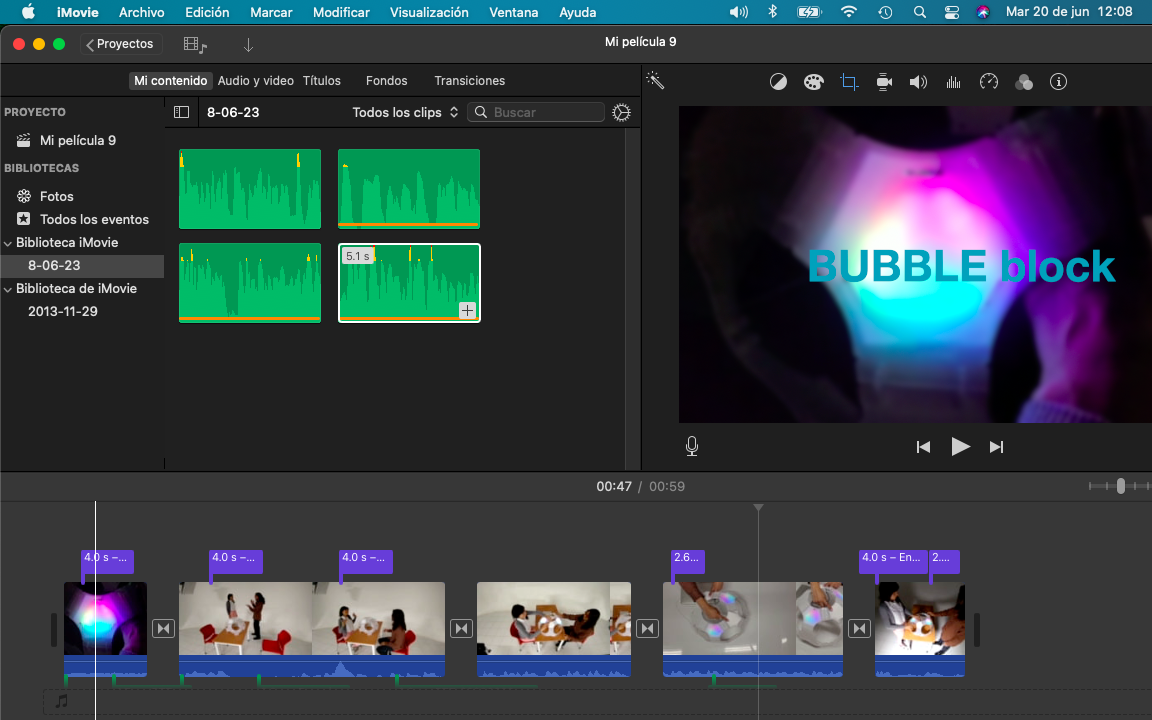
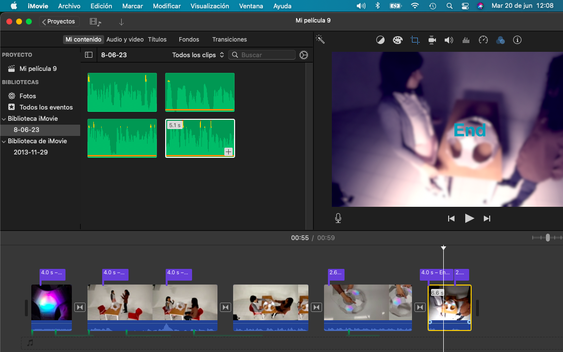
To improve productivity in stressful tasks, such as creating a new project, it is advisable to take about 5 minutes to distract yourself, a distractor is necessary to improve interaction with our colleagues or with ourselves, which is why this structure can be used to "Make music with the heart", can be used individually or with 2 members. In addition, the structure can be adapted to different seasons depending on the size where it is, you can create a flat structure or a sphere.
Application designed in week 14.

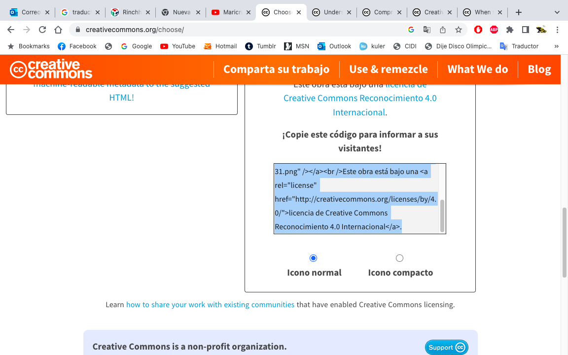
I had no idea what license to use, because I wanted the project to be free, but I see that I would agree with the "Creative Commons" license, it is an organization that focuses on community knowledge and culture. Use Attribution 4.0 International (CC by 4.0), because it is a broad community where learning is shared, but the creator is rewarded, which is a very favorable point for my own growth.

I made my sheet in Illustrator, it is a program that is not free, but it is very complete, here I "embed" the images that I wanted to use and I was placing the information as if it were an infographic, ordering the steps and processes that I followed to finish my project final.
Make your slide 1920 x 1080 px, and name it as: presentation.png
Do not forget that in illustrator it is saved with the template activated so that it respects your measurements.
I saved my presentation directly in the "public." folder, in this process my advisor Oliver helped me a lot.


To make my video I did it in the Mac IMovie program, if you work in one you can use it and it's free. The program is very intuitive and lets you drag your content to build your video, it also has various settings installed to add effects to your video. The video must be 1 min long and it must be compressed, what I did was make the video in high quality and then upload it to YouTube, then I downloaded (use a page to download your own content) it and it weighed less, because You Tube compresses them and tries not to lose quality.