Electronics design
Week 6 - Documentation
Design rules
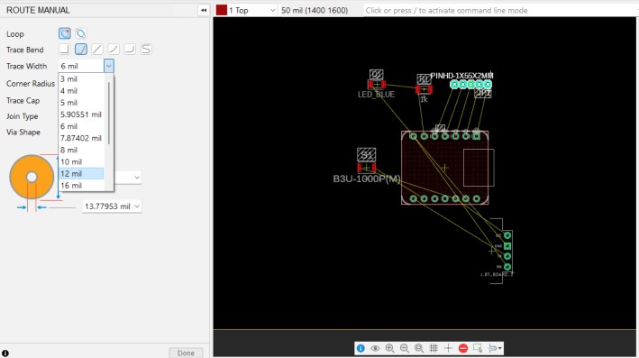
For the designing process of the PCB there are come considerations to take account. I'm using a guideline found on the internet, which I think is complete and descriptive for every beginner in electronics design. My PCB is intended for a copper plate of 35 um. So, I'm using the following table to choose the track widths:
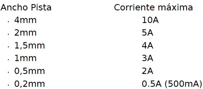
Recommendations and rules on the layout of tracks (taken from: Basic Standards and Recommendations in the Design of PCBs )
- The minimum distance between tracks and the edges of the plate will be of two tenths of an inch, approximately 5 mm.
- Tracks will not be passed between two active component terminals assets (transistors, thyristors, etc.). If needed, it can be done between passive component terminals.
- The plate must be fastened to a chassis or box; for this, a 3 mm hole will be arranged in each corner of the plate.
- When two or more tracks run parallel, it should be keeping the separation distance.
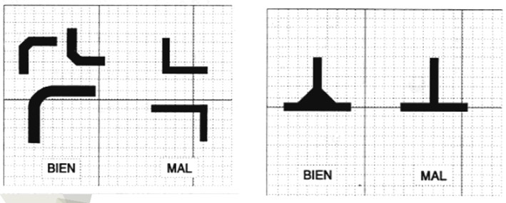
When laying out the tracks it is convenient to avoid the layout of 90 angles. (taken from: Basic Standards and Recommendations in the Design of PCBs )
Design of a development board
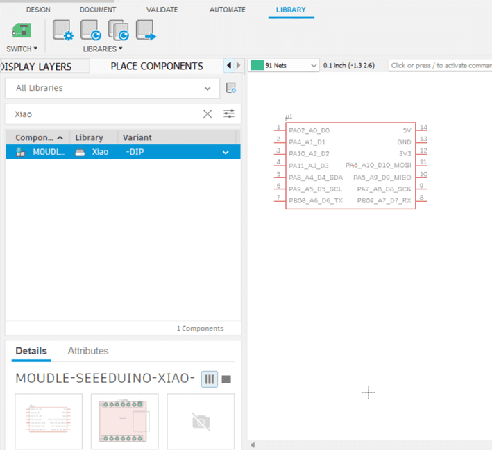
The individual assignment of this week consists of designing the electronic board for our project. For now, I'm going to use a microcontroller XIAO SAMD21, because it has more analog outputs than the XIAO RP2040, which I need for all the fingers of the Pianonator.
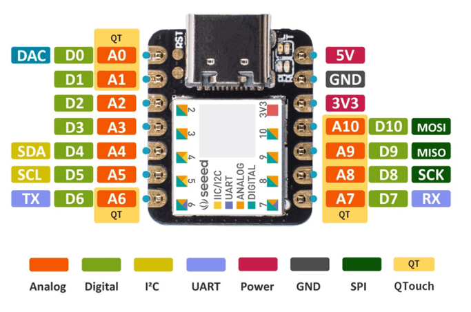
Image taken from Seeduin-Xiao
For the communications, I'm going to use a Bluetooth Module:
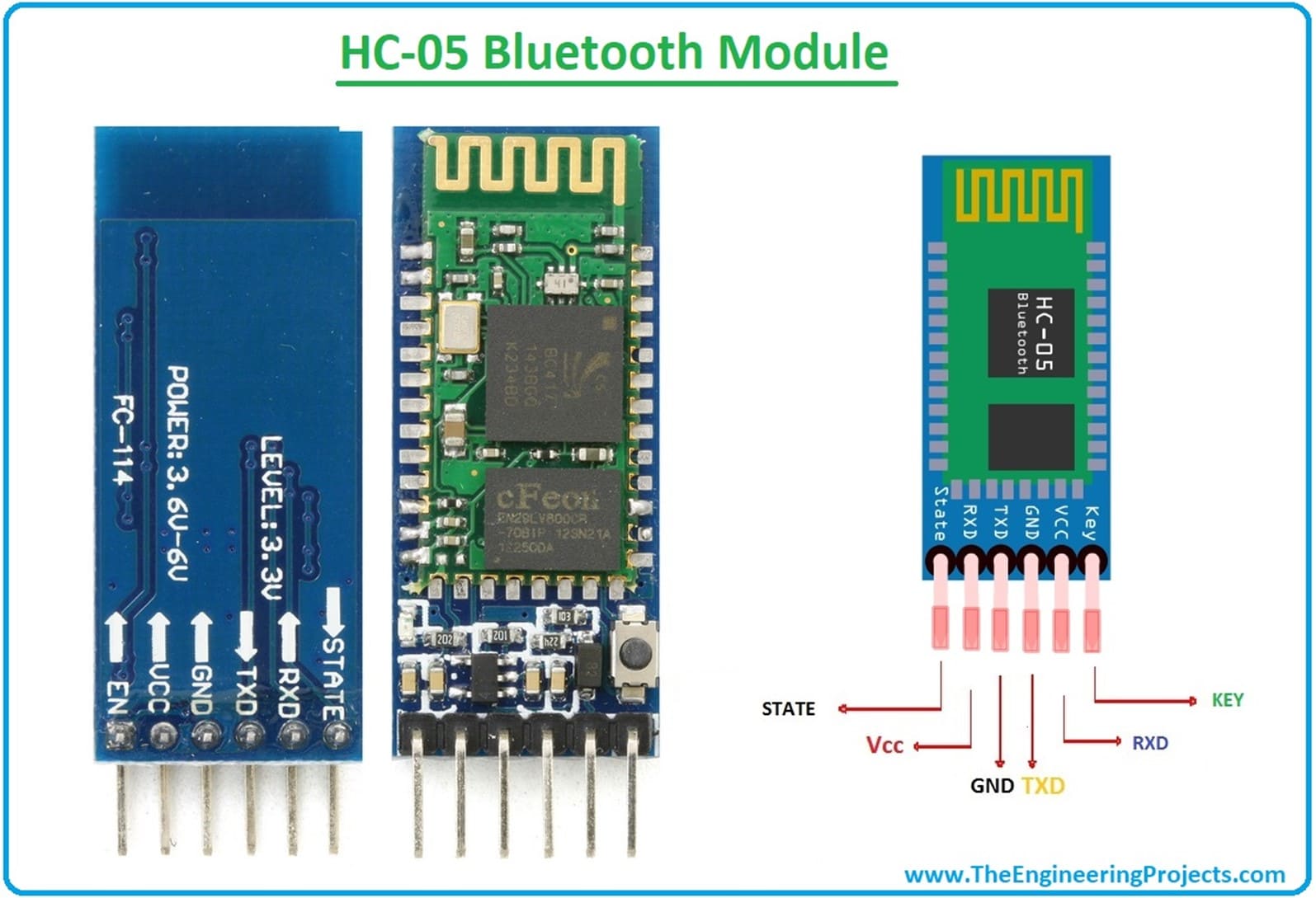
Image taken from Theengingeeringprojects.com
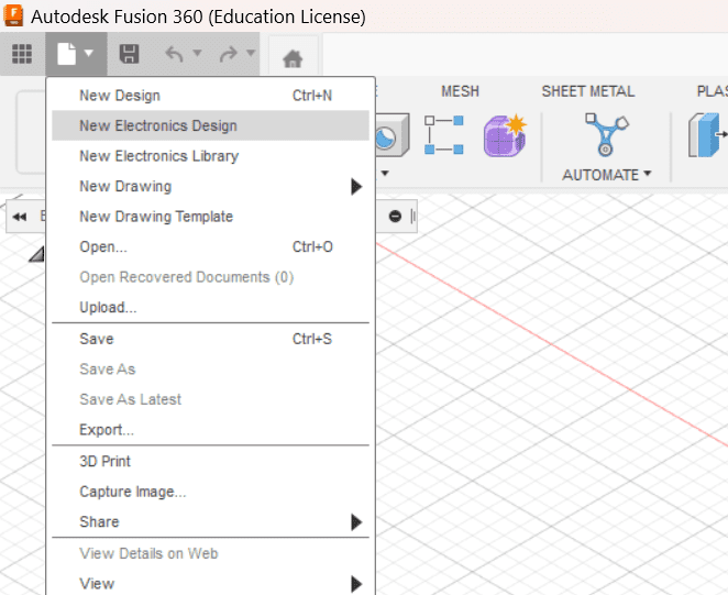
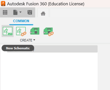
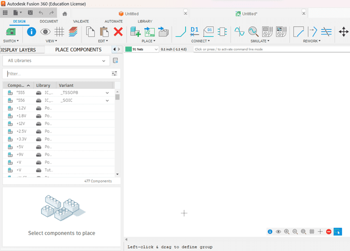
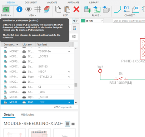
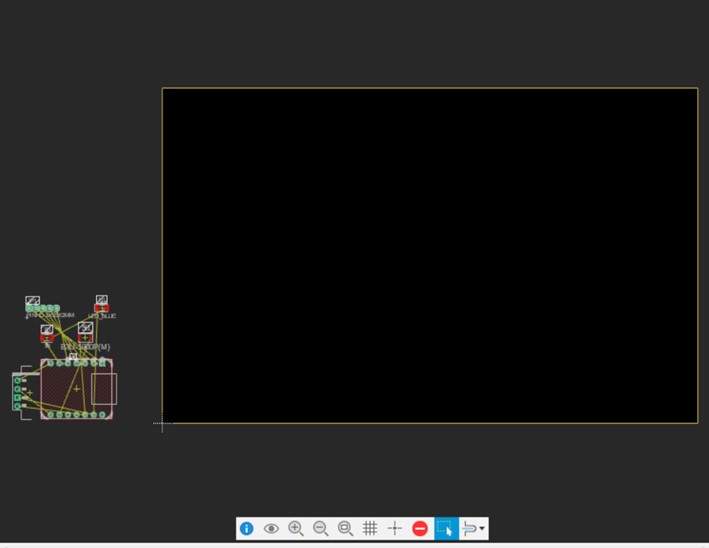
To design the electronic board, I'm using Fusion 360. Here are the steps:


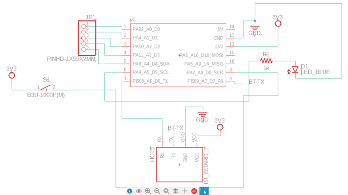
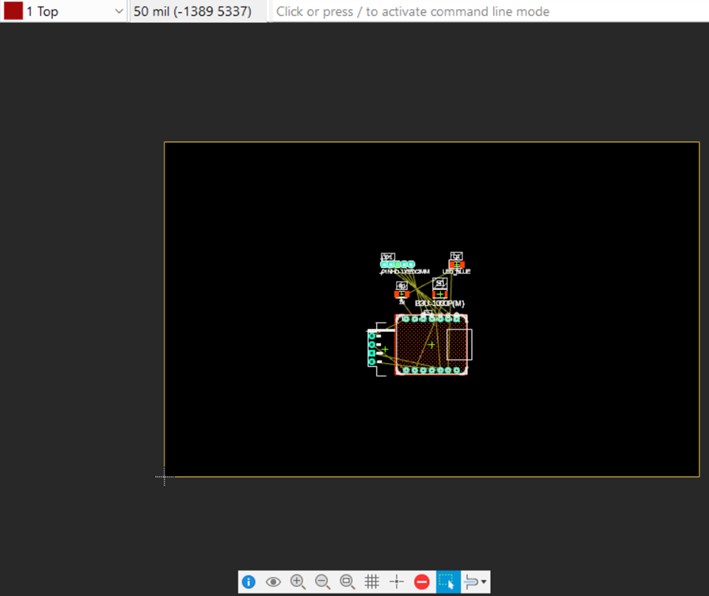
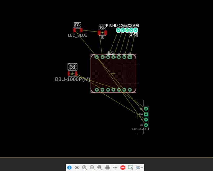
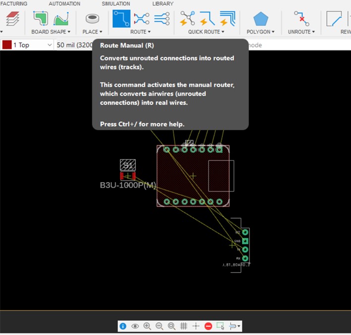
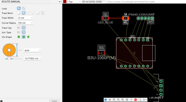
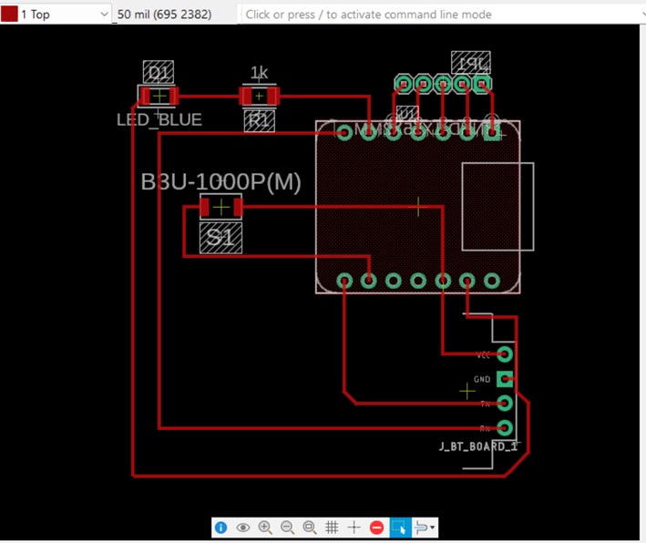
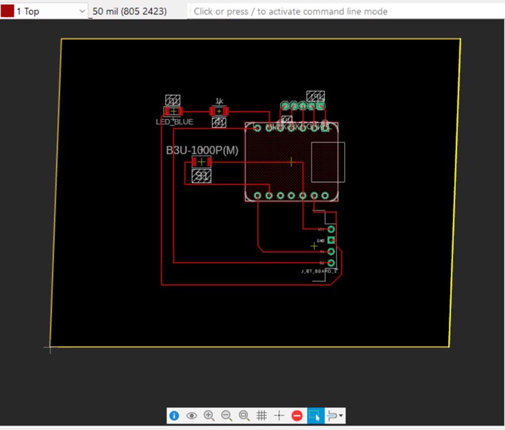

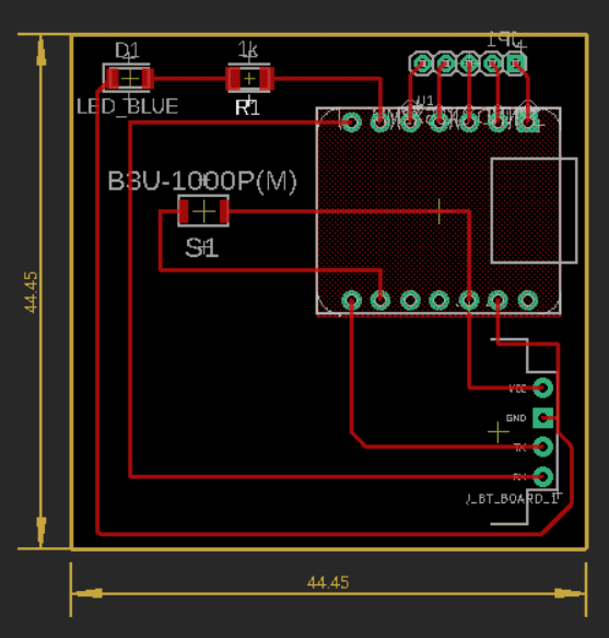
My final PCB design:
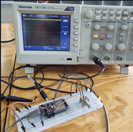
Using Lab Equipment to Observe my Microcontroller
- Lab equipment 1: Tetronix Two Channel Digital Storage Oscilloscope
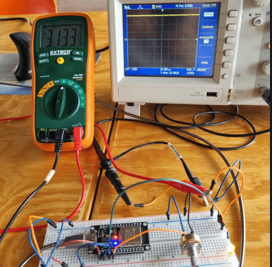
- Lab equipment 2: Digital Multimeter
- Microcontroller: ESP32 Dev Kit.
- Electronics:
- Led
- 330 ohm resistor
- 10K potentiometer
- Jumpers
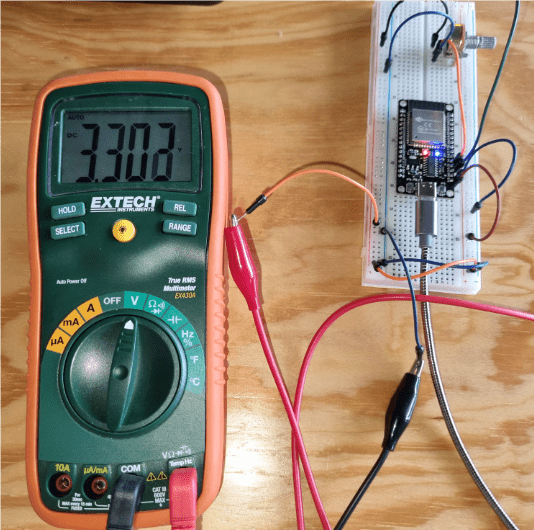
The Esp32 works with 3.3V, so first we are going to measure that:
Blinking Led
Now, we are going to observe the on-off effect from the blinking led example.
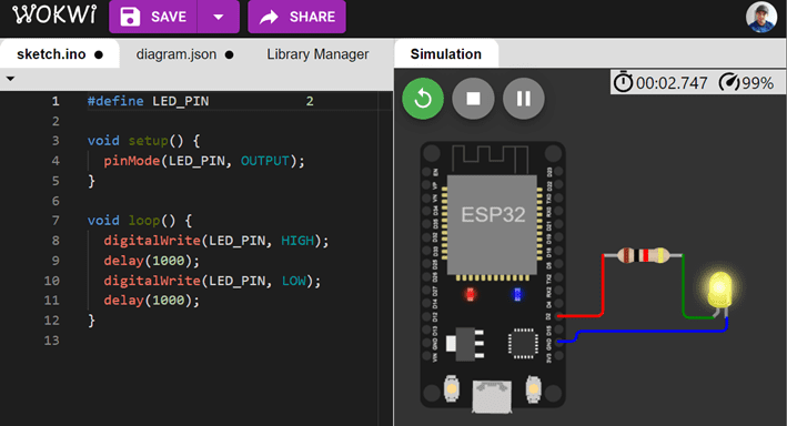
When we measure the output of the esp32, we can see a square signal in the oscilloscope, going from 3.3V to 0 every second, as seen in the next video.
Input and Output Voltages
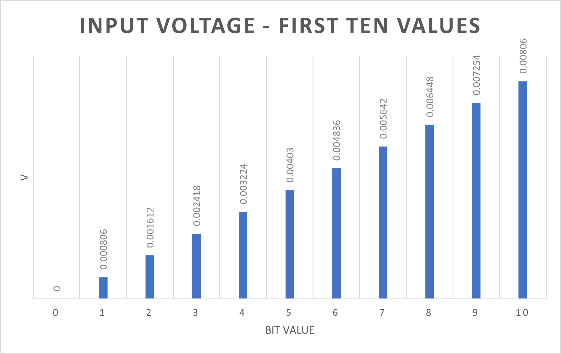
The analog input pins from the esp32 have 12-bit resolution, meaning that the range varies from 0 to 4095, having 0 for 0V and 4095 for 3.3V. In other words, the resolution of every bit is of 0.000806V! In the next graph, you can see the linear behavior for the input resolution.
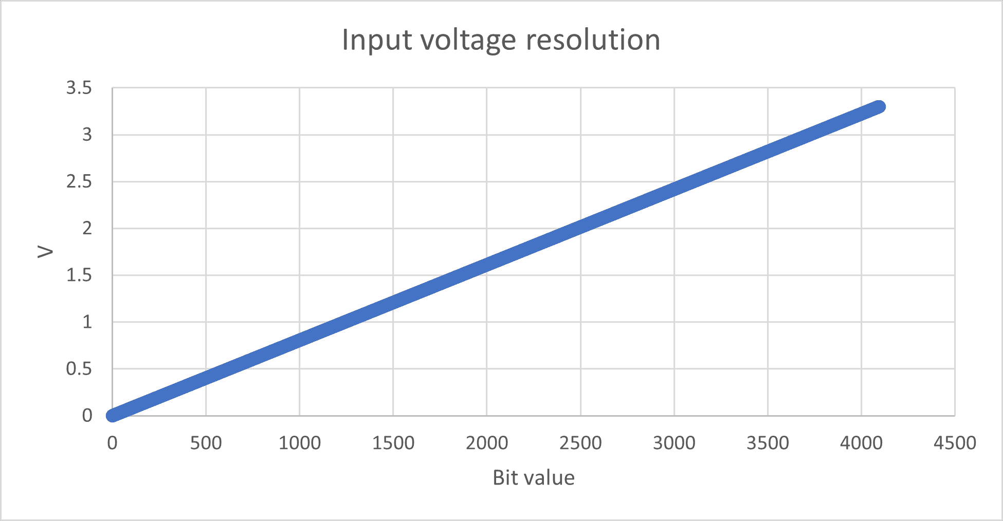
If you zoom in, just to observe the first ten values, you can understand how small the voltage difference is.
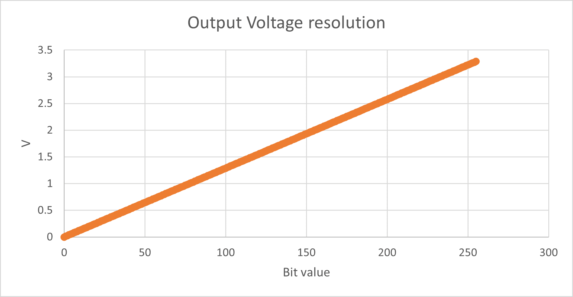
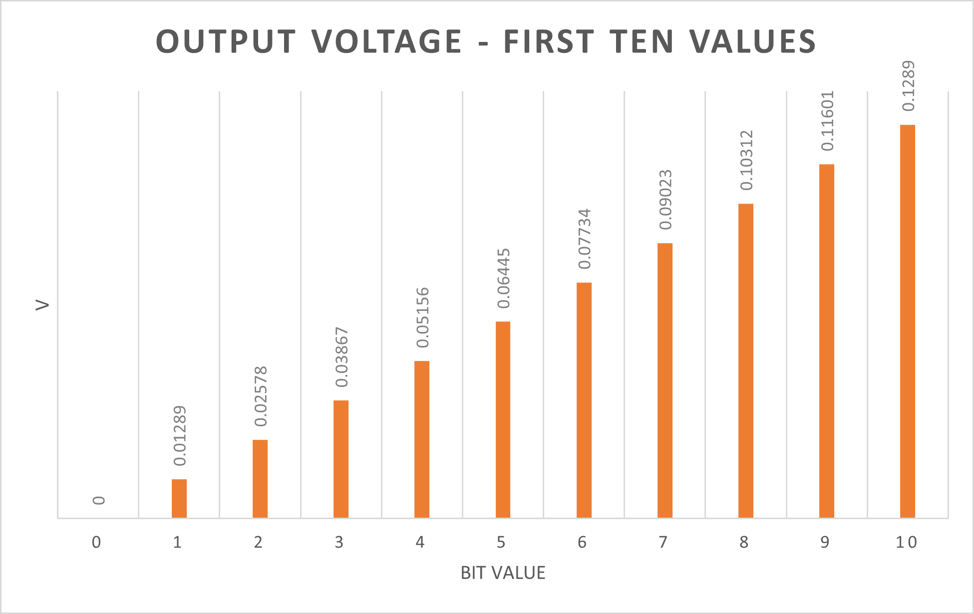
In contrast, the analog output pins from the esp32 only have 8-bit resolution, meaning that the range varies from 0 to 255, having 0 for 0V and 255 for 3.3V. In other words, the resolution of every bit is of 0.01289V. In the next graph, you can see the linear behavior for the output resolution.
If you zoom in, just to observe the first ten values, you can see the voltage difference between each value.
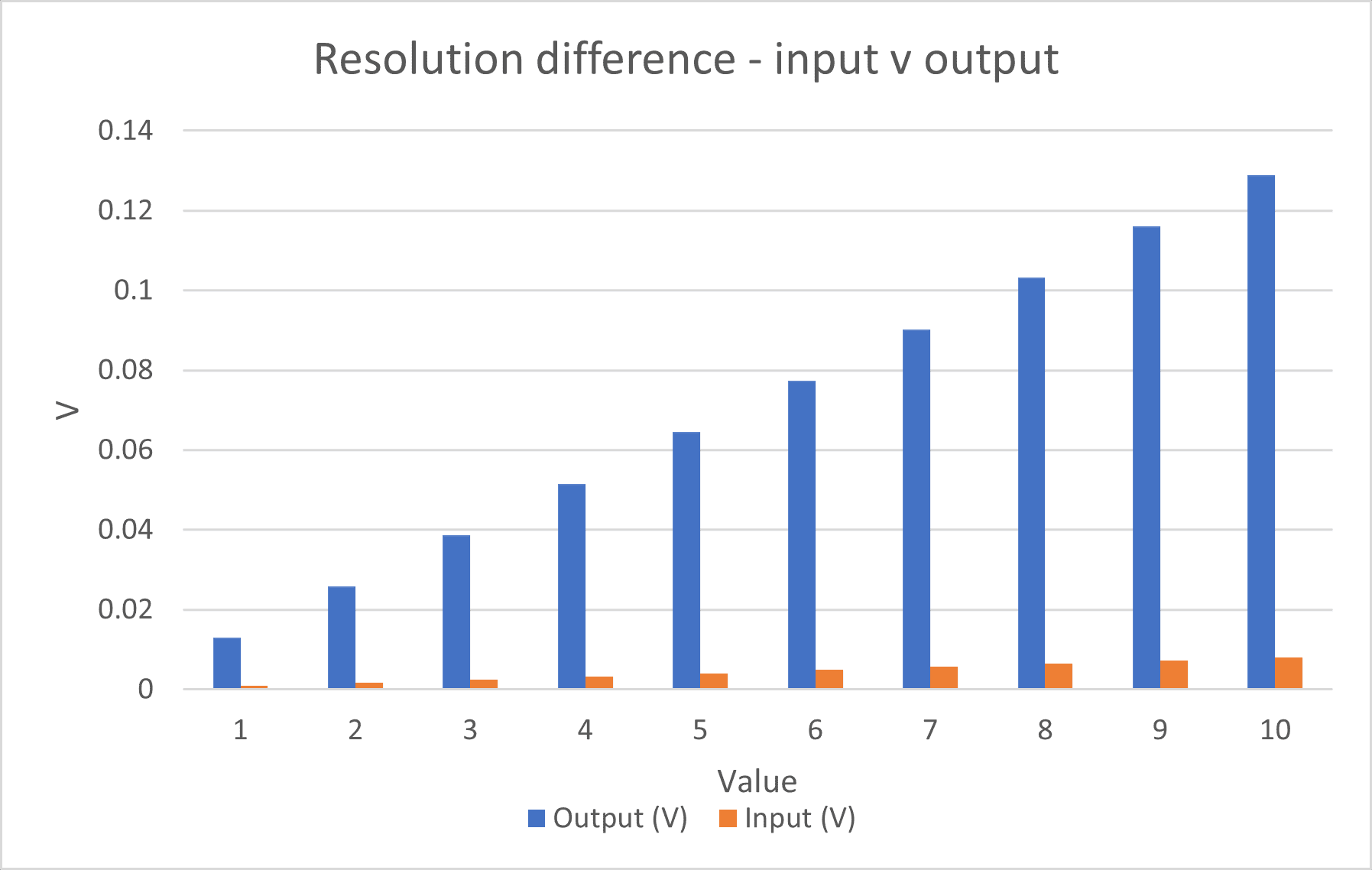
Now, let's compare the voltage resolution of the first ten values for the input and output resolution.
"Analog Output" - PWM Signals
PWM stands for pulse with modulation, and it is used to obtain analog results by modulating digitals signals. Microcontrollers are digital devices, and as far as I know, none of them all can operate with pure analog outputs. Digital signals are those of On and Off, True and False, 1 and O… Basically, it operates in two states, meaning it is a discrete signal. In contrary, analog signals can vary in between two extreme points, having a continuous behavior.
The next image is a representation of the difference between the analog and digital signals.
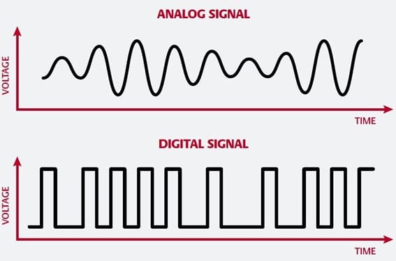
Image taken from Digital Audio Cables
The microcontroller modulates the pulse width of the digital signals, hence the name PWM, to mimic the analog characteristic of having a state between two values. An on-off pattern, square wave, is used, where the moment the signal is “on” is called pulse width. By modulating the pulse width in each period results into an in-between value from the on-off scale, allowing us to have “analogic” signal.
The next image is a representation of how the PWM works in microcontrollers:
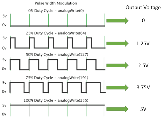
The image was modified from the original one taken from: Basics of PWM (Pulse Width Modulation)
Now that we now what PWM signal are and how we can use is to give us analog outputs in our microcontrollers, let's test it.
I'm using a potentiometer to fade a led with my esp32. The potentiometer will be the analog input and the fading led will be the “analog” output.
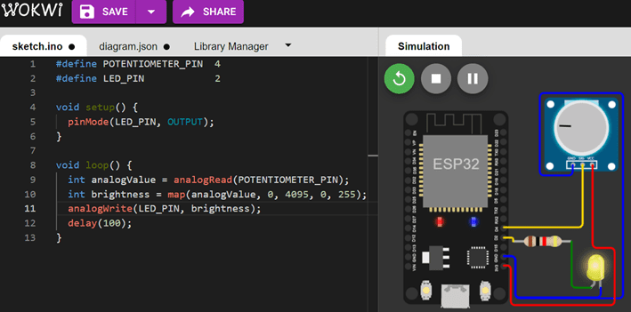
The following video shows the behavior of the output signal measured with the oscilloscope and the multimeter when I'm changing the input values with the potentiometer. You can observe, as well, how the intensity of the LED varies with it.
You can download the electronic's design files: