Week_14: Interface and Application Programming

This week's assignment is quite complex, as one must create a program that can connect with an app developed entirely for this purpose. The basic principle of the app and program I created is that one has a color selection app, then it connects via Bluetooth to the ESP32, it inteprets the data it recieves and turns a RGB LED on with the precise color being sent to it. It's not supposed to be that difficult, but it took me a lot of time, and errors. Let's start from the begining.
The Code
I started using the same code as the one in Week_13: Networking and Communications, in which a smartphone can connect to the ESP32 Via Bluetooth, and send data. I then modified the code for it to, first write it down in the "[XXX, XXX, XXX]" format, as it is sent from the app. Then the code must be interpreted and stored in the variables R, G and B. Then
we use the tool called "mapping" in which we convert the 0-255 range, into 0-100 range, because we must now use this number as a percentage of the duty cycle for the PWM pins. Having this, then we must write the propper frequency
into the R, G and B pins, in which there is a RGB LED connected respectively. This is the code:
#include "BluetoothSerial.h" //This library has the Bluetooth Capabilities for the program
#if !defined(CONFIG_BT_ENABLED) || !defined(CONFIG_BLUEDROID_ENABLED) //This three lines make sure that the bluetooth is enabled
#error Bluetooth is not enabled! Please run `make menuconfig` to and enable it // and ready to connect, if not, it starts again
#endif // until it is propperly enabled.
BluetoothSerial SerialBT; //This creates and instance called SerialBT.
int R = 0; // Red Variable
int G = 0; // Green Variable
int B = 0; // Blue Variable
void setup() {
Serial.begin(115200); //We begin the Serial communication at a baud rate of 115200
SerialBT.begin("Bbto32"); //This defines the device's name as "Bbto32"
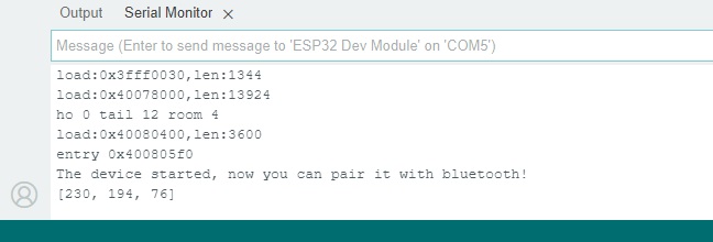
Serial.println("The device started, now you can pair it with bluetooth!"); //This promt will be printed as soon as the BT is
//initialized.
pinMode(32, OUTPUT);
pinMode(33, OUTPUT); //We define the pins with the PWM in these lines.
pinMode(25, OUTPUT);
}
void loop() {
if (SerialBT.available()) {
String data = SerialBT.readString(); // Reads the recieved data
if (data.startsWith("[") && data.endsWith("]")) {
data = data.substring(1, data.length() - 1); // This part over here interprets the full input and converts it into
int commaIndex1 = data.indexOf(','); // the values for R, G and B variables.
int commaIndex2 = data.indexOf(',', commaIndex1 + 1);
if (commaIndex1 != -1 && commaIndex2 != -1) {
String rString = data.substring(0, commaIndex1);
String gString = data.substring(commaIndex1 + 1, commaIndex2);
String bString = data.substring(commaIndex2 + 1);
R = rString.toInt();
G = gString.toInt();
B = bString.toInt();
// Mapear los valores de 0-255 a 0-100
R = map(R, 0, 255, 0, 100);
G = map(G, 0, 255, 0, 100); //This part over here is the mapping to convert the values into percentages
B = map(B, 0, 255, 0, 100);
// Actualizar los ciclos de trabajo del PWM
analogWrite(32, R); // Output for the 32 pin (Red)
analogWrite(33, G); // Output for the 33 pin (Green)
analogWrite(25, B); // Output for the 25 pin (Blue)
}
}
}
}
The App
For the app, I used this really interesting tool called MIT App Inventor with a really friendly interface. First we design the layout by dragging and dropping the elements from the menu, in this case i needed a list of available bluetooth devices, 3 sliders for each color, 1 button for sending the color to the ESP32, and one way to display which color was going to be sent.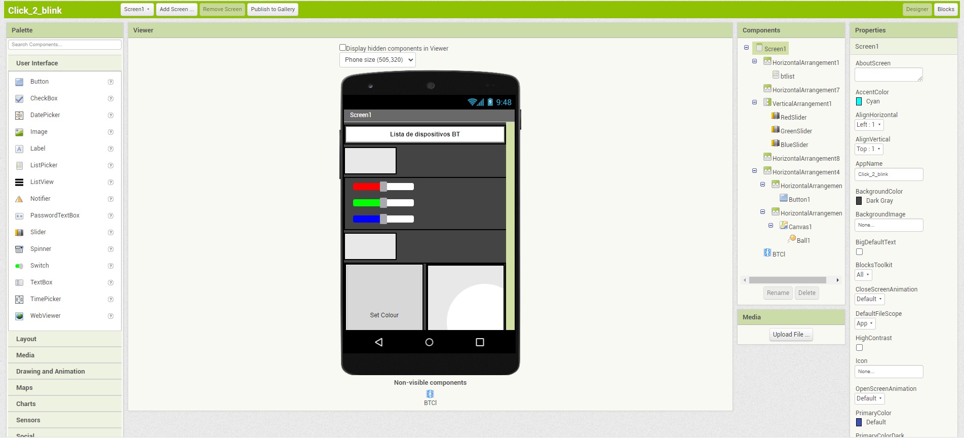
Having the best layout defined, it is time now to program by using blocks. The blocks are inter-connected to do certain tasks. For example, the seccond image shows a block that writes the value of the slider for the red color.
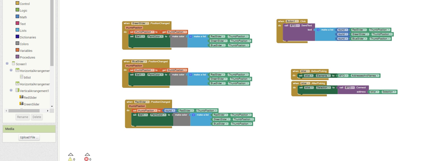
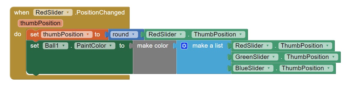
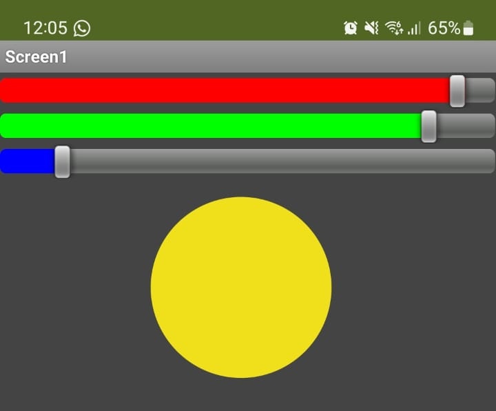
The block/Code works something like this. First we get a list of the available devices in which we must connect to the ESP32 named "Bbto32". Afterwards we get the position of each slider and change the color of the circle to that one. When we press the button, we send the data in the
"[XXX, XXX, XXX]" format via bluetooth to be interpreted by our magnificent microcontroller.