Week_07:Computer Controlled Machining
For this week's assignment we are building something BIG. In this case I need a Sofa/Rocking Chair. But safety precautions first.
Safety training
As this is a very dangerous machine we need very specific precautions for its propper use. First we need protection from the dust and other elements that the machine generates. We need to protect eyes and respiratory system with safety goggles and a breathing mask for fumes and dust. We also need a lab coat for protecting the skin, and work-boots for any heavy material handling. We do not encourage our users to wear gloves at all times, just when they're manipulating the material sheets and fixing them into the work area, just to avoid splinters and cuts. We have a no-entering zone, which goes around 40cm around from the machine, this is to avoid being too close to the spindle and material. The rules dictate that we have at least 2 persons working on the piece at all times just in case the machine needs to be stopped at any time. I always teach the users to be aware of any fixtures or irregularities on the material, to always have their finger on the Pause button of the controller, in case something has to be changed, or there is an error on the G-code. The dust extraction system is to be turned on as soon as the machine starts the cut, to avoid clogging and projectiles. The rules are clear with baggy clothes or accesories, as one must remove necklaces, earings or any hindrance that could get in contact with the machine, also the hair must be tied for the same reason. Having all the safety measures clear and understood, it is now time to design and cut something BIG.The chair
I need to either upholster it or add cushions for maximum comfortability. Also, the chair needs legs but it is still usable without them. The first part was small research about ergonomics and measurements using the book: “The Measure of Man & Woman: Human Factors in Design” from Henry Dreyfuss Associates.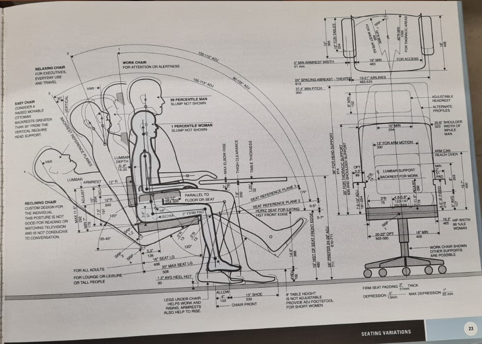
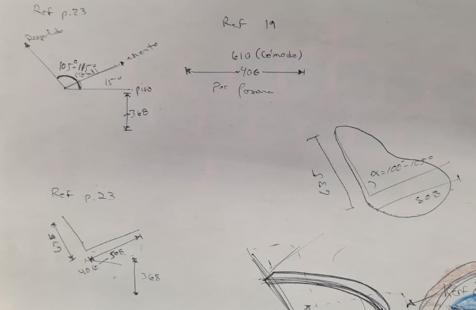
With this reference I came up with the next measurements for the chair:
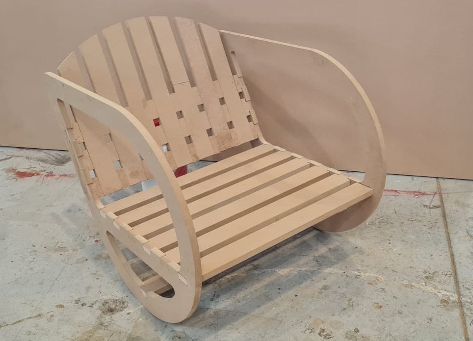
And then the sketching process started for the final shape.
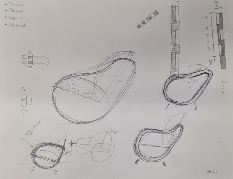
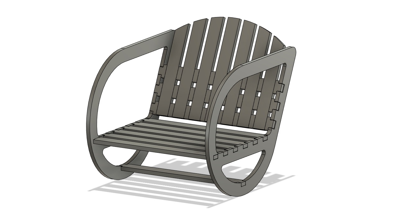
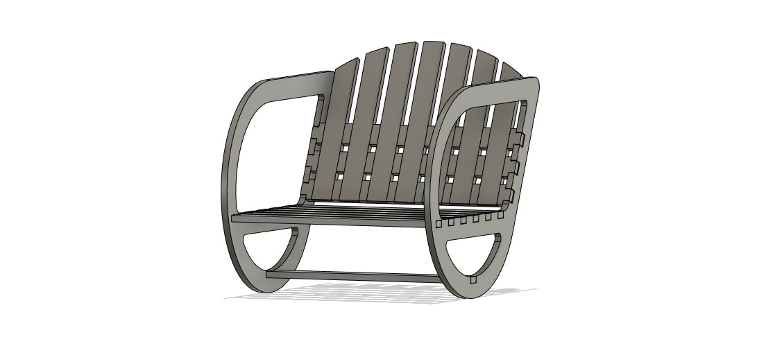
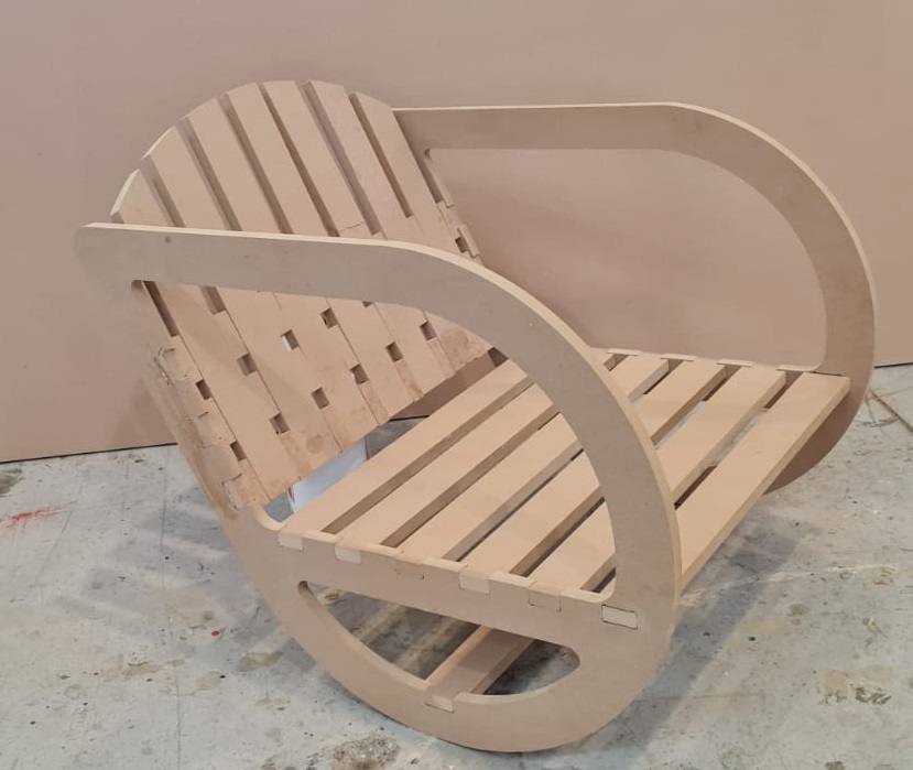
The final design has a droplet shape with supports on the back that weave with pocketed areas and snap-fits.
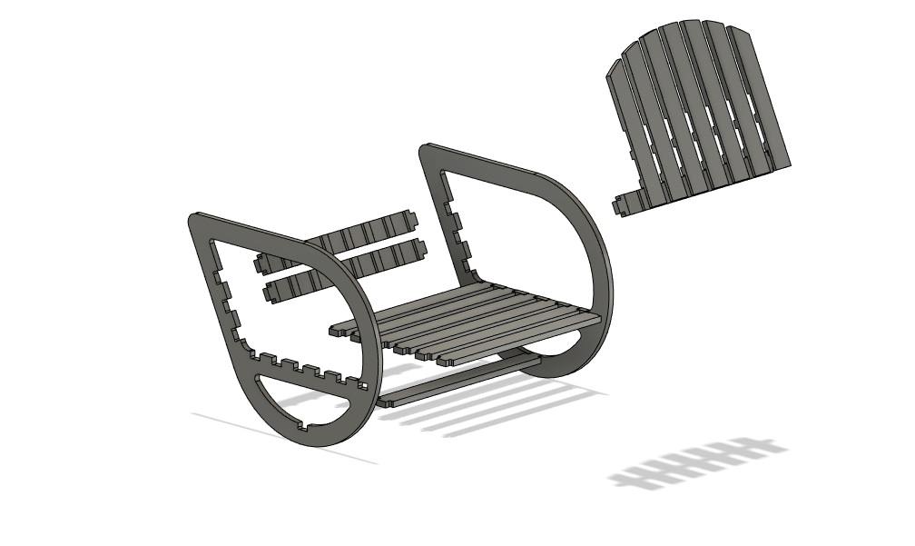
The next part is to design it on Fusion 360, with each piece on a different file for later assembly.
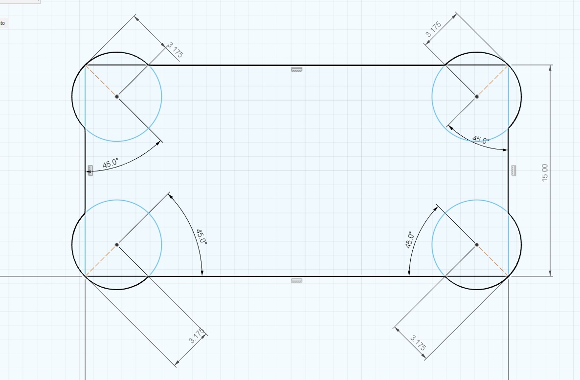
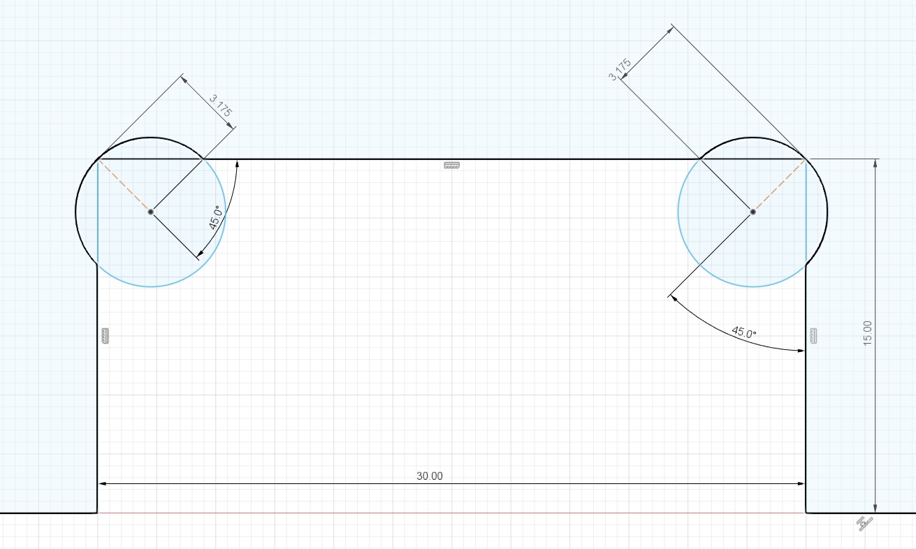
I had a slight notion about the design for the joinery, so I experimented with the shapes for it to have a proper fit. The holes, or Tenons, would have rounded corners because of the router bit, so that had to be taken in consideration. Firstly I drew the box in which the Mortises will be joint, then I added a 45° line with the lenght of the radius of the router bit, in this case it is 1/4 of an inch or 3.175mm. The next step is to draw a circle with that same radius, and erase the excess lines. This shape/process is called a DogBone, because it kind of looks like a bone for a dog (¿?).
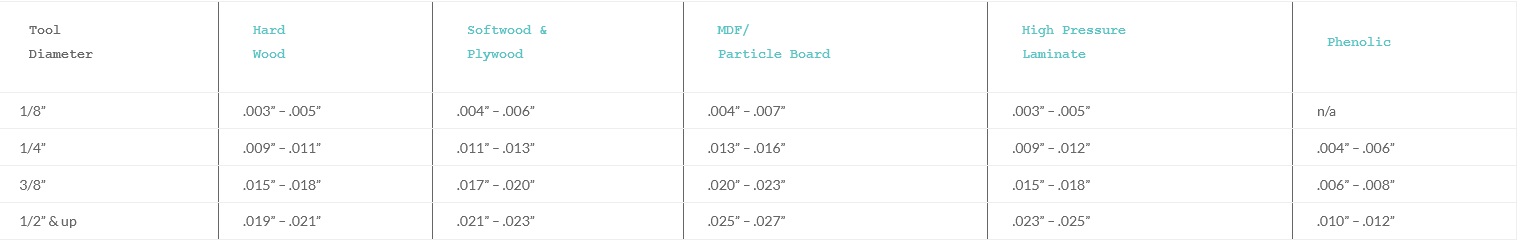
Anyways, then we need to do some math in order to calculate the proper speeds for the program to be run on the CNC Router. Firstly, we have the Chip Load, which means the thickness of the material that is removed by each flute, or cutting edge, during a revolution of the spindle. This number generally comes in inches and milimeters and depends on the material being cut and the diameter of the tool. Here we can see a chart with this information. I would also recommend to visit the manufacturer's website as they provide this information as well.
We need more numbers to properly machine with the CNC Router. The concept of Feed Rate is the speed in which the tool travels in the work area, and it's mostly measured in mm/s or in/min. It depends on the Spindle Speed, number of cutting edges, or flutes, and the Chip Load. The formula is
SpindleSpeed x NumberOfFlutes * ChipLoad. The Spindle Speed is a bit tricky, because the goal is to select the lowest RPM possible, as higher RPM generate more friction, this is what dulls the router bits. However, the high RPM guarantee better
surface finishes. For metric conversion is easier to divide inches per minute (in/min) by 39.374, and you get m/s. The Depth of each cut is also determined by the diameter of the tool, and a very accurate rule of thumb is to never surpass the diameter Max Depth = Diameter of bit.
Another important concept is StepOver: It means the distance between each of the passes of the tool, and as another rule of thumb StepOver = Radius of bit.
Fortunately, most of this information can be found either with the manufacturer, or at online calculators Here is an example.
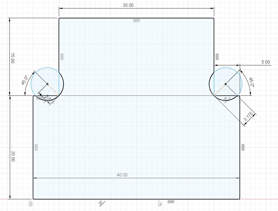
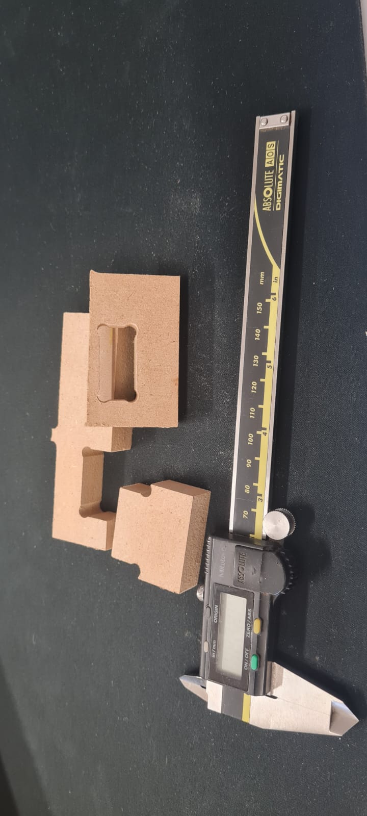
That being said, the next part is to design a quick test for the mortises and tenons designed on my chair. Firstly I didn't take into account any other factor than size, having the mortise measure 15mm x 30mm, with the propper dogbones. I cut them using the software Vectric Vcarve, a really powerful software to convert digital objects such as
vectors, 3D models, and bitmaps, into Gcode for CNC Machining, apart from having a great catalogue of compatible machines.
Having the cut pieces, I measured all the dimensions in order to compensate the error on the final piece of furniture. Then applied this changes to the same test and re-cut it, having a propper tight-fit.
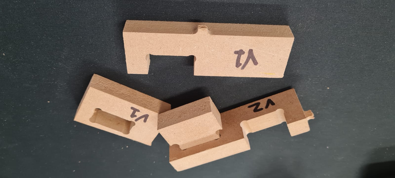
Fortunately the design for the chair was done using parametric values on the mortise/tenon parts, so the update on the definitive measures was a piece of cake. Having the blueprints accurate and ready, we now have to configure the machine for cutting the 15mm MDF panel. The process for exporting vectors from Fusion360 is quite easy, as one selects the sketch to be vectorized, right-click it and then
Save it as .DXF Easy as that.
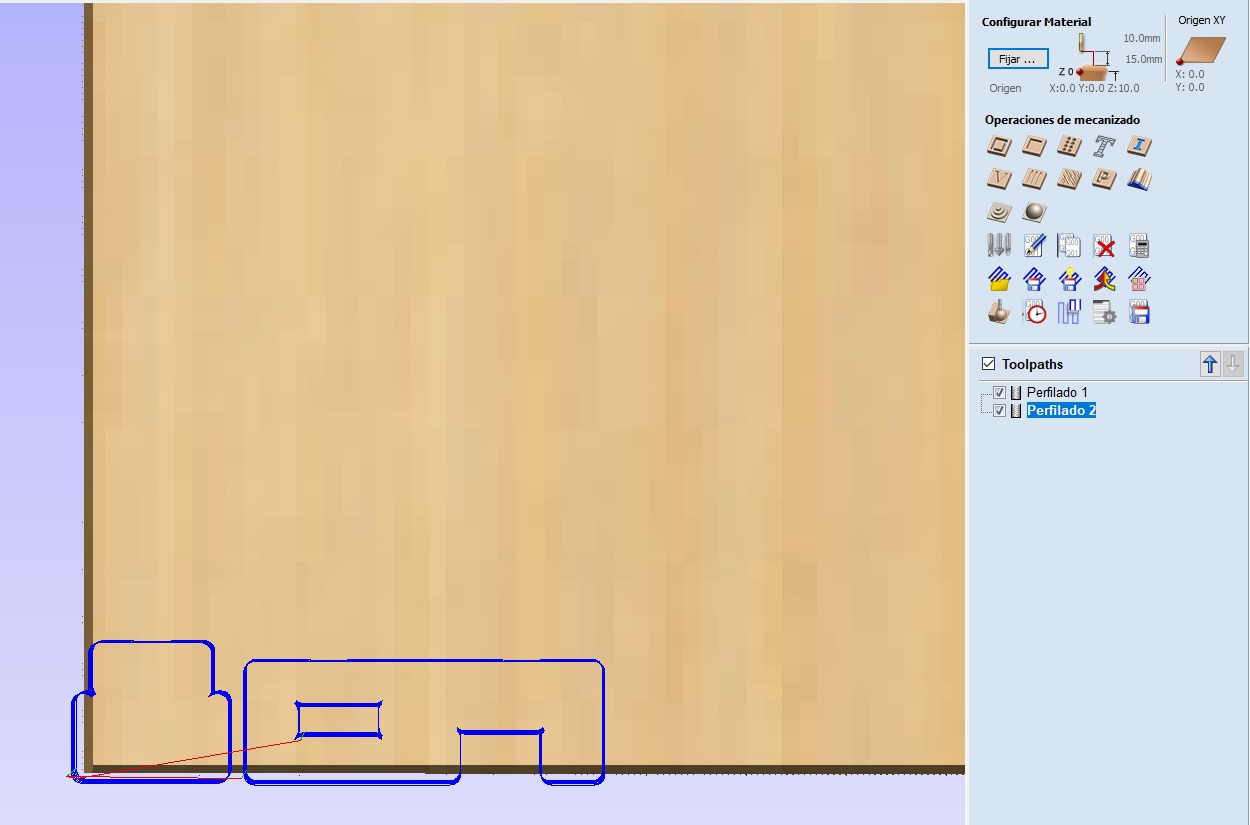
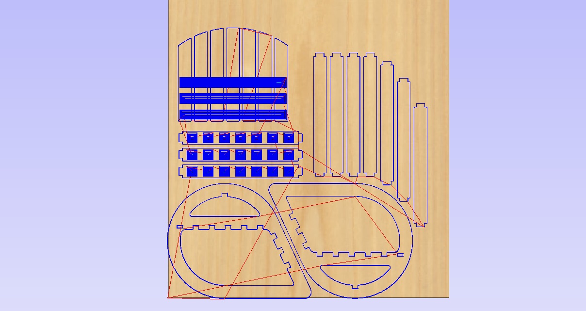
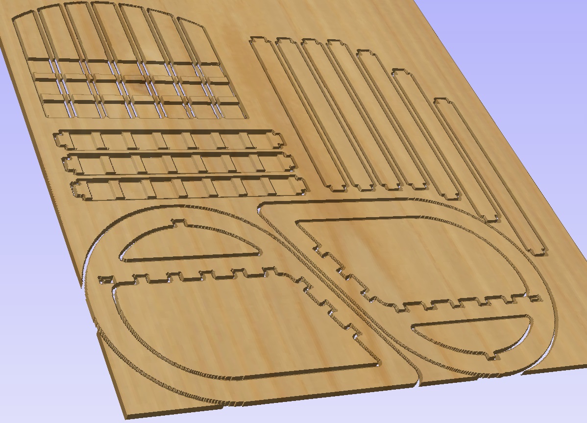
Opening a new file on Vcarve starts the prompt to select the size and width of the material to be processed. Then one can import the vectors and locate them on the best way possible (we try to waste as little as possible).
Having all the vectors properly aligned, we must tell the machine which vectors are to be cut from the outside or the inside of the lines, this is meant to compensate for the Kerf, i.e. the material that is removed by the tool.
There are different kind of operations that can be perfomed by the CNC Routers, for example we have Profile, Pocket, Engraving or 3D Roughing.
What Profile operation does is to follow a vector up to a certain depth, either on the inside or outside, or over the line. The Pocket operation removes the material bounded by the vector, up to a certain depth. And the Engraving is mostly used for lettering and different size strokes, generally using a V-shaped cutter.
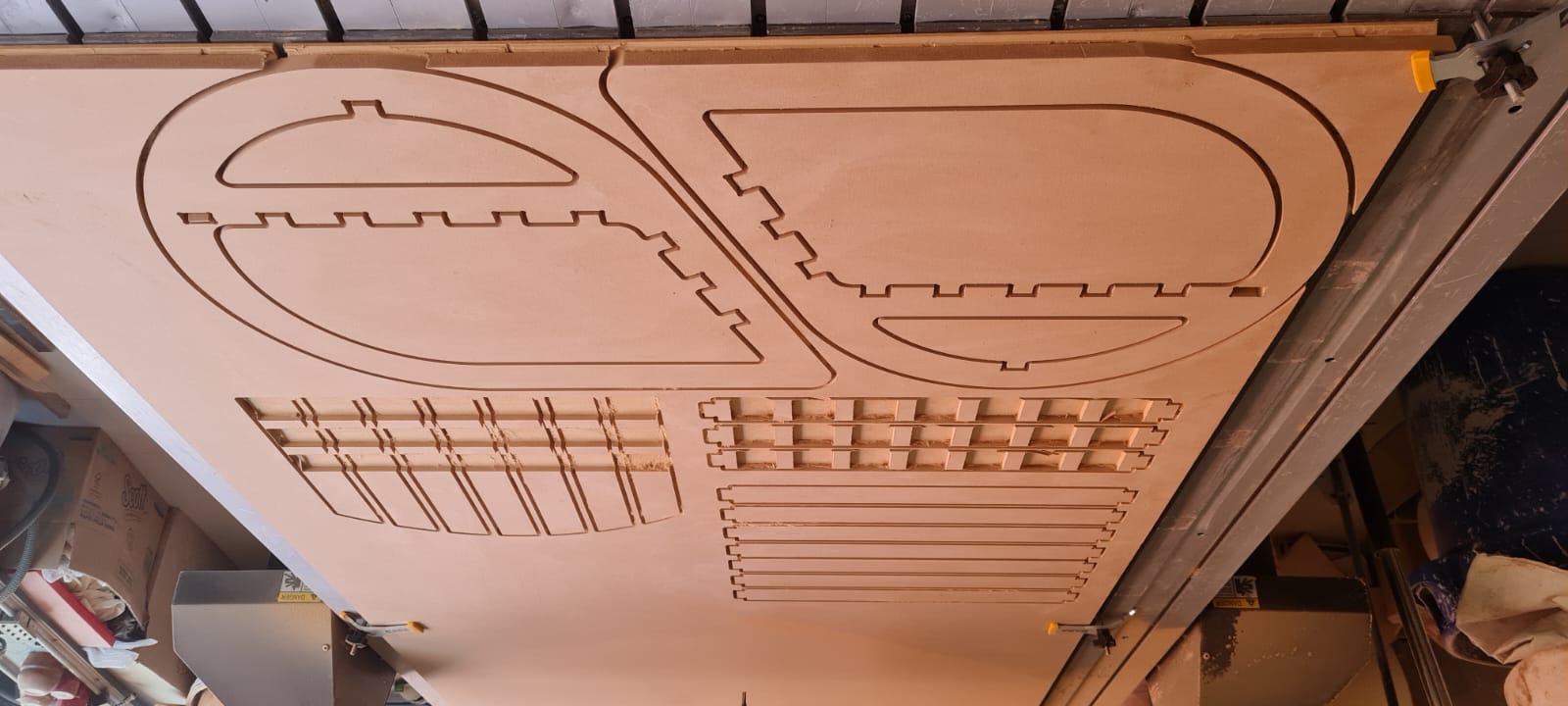
For the chair I used Profiles on the outside-of-the-vectors for the overall shape, on the inside-of-the-vectors for the mortises and inside shapes, and Pocket for the splices of the "woven" back-rest pieces.
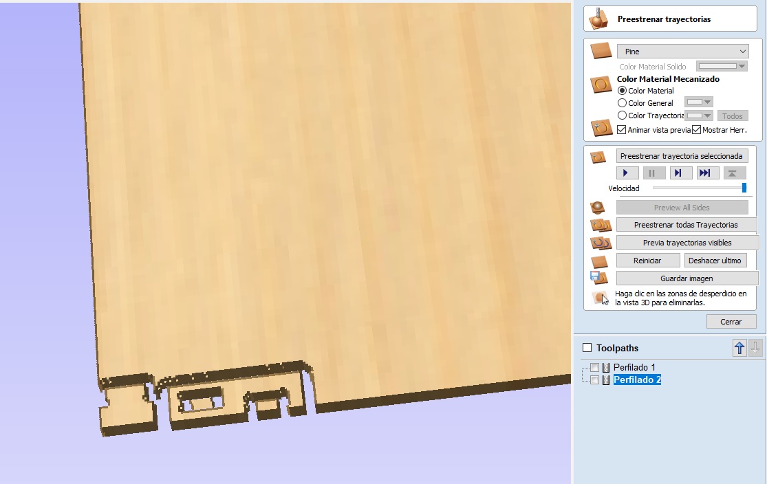
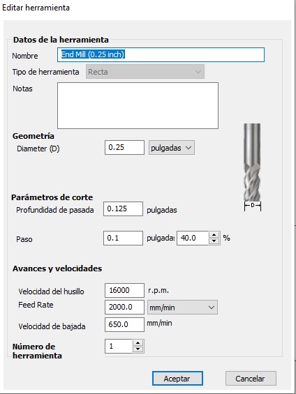
All of this was configured using a 1/4in endmill, with 2 flutes, with the next parameters:
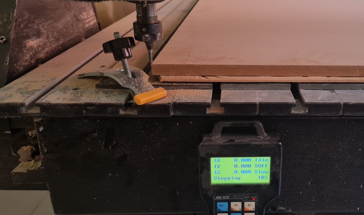
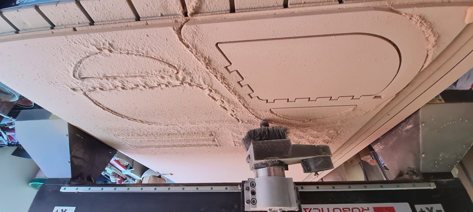
Having this (hopefuly) programmed, I exported using the Asia Robotica SHOP-1325 Post-processor and prepared the material. Using the clamps provided by the manufacturer, I secured the MDF Panel, then loaded the file through the controller interface via USB memory stick, and then told the machine where the XYZ(0,0,0) point is located, by moving the spindle to the lower-left corner of the piece and touching the surface of the material. The next step is to run the program and Voilá! after a couple of hours of cutting we now have a chair.
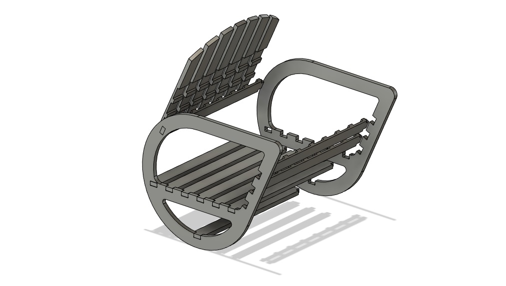
The post-processing of the pieces was minimal as I only removed the tabs that kept the pieces from flying around the shop, with a belt-sander.
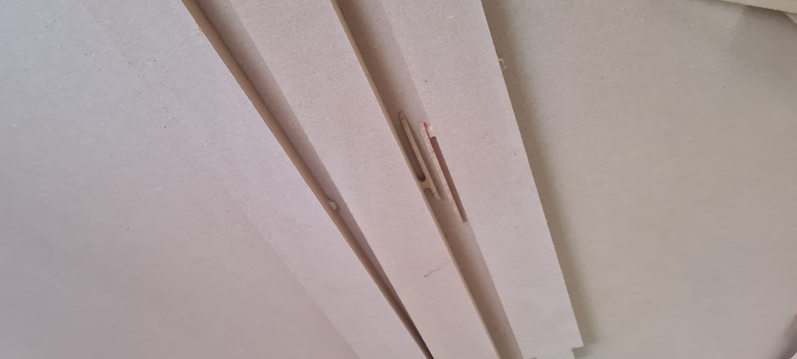 The joints were a bit tight but nothing that a rubber-mallet and some elbow grease couldn't do.

I have included the
*.dxf* files for each piece, as well as the fit-test for cutting, on the Downloadables Webpage.
Extra, extra!
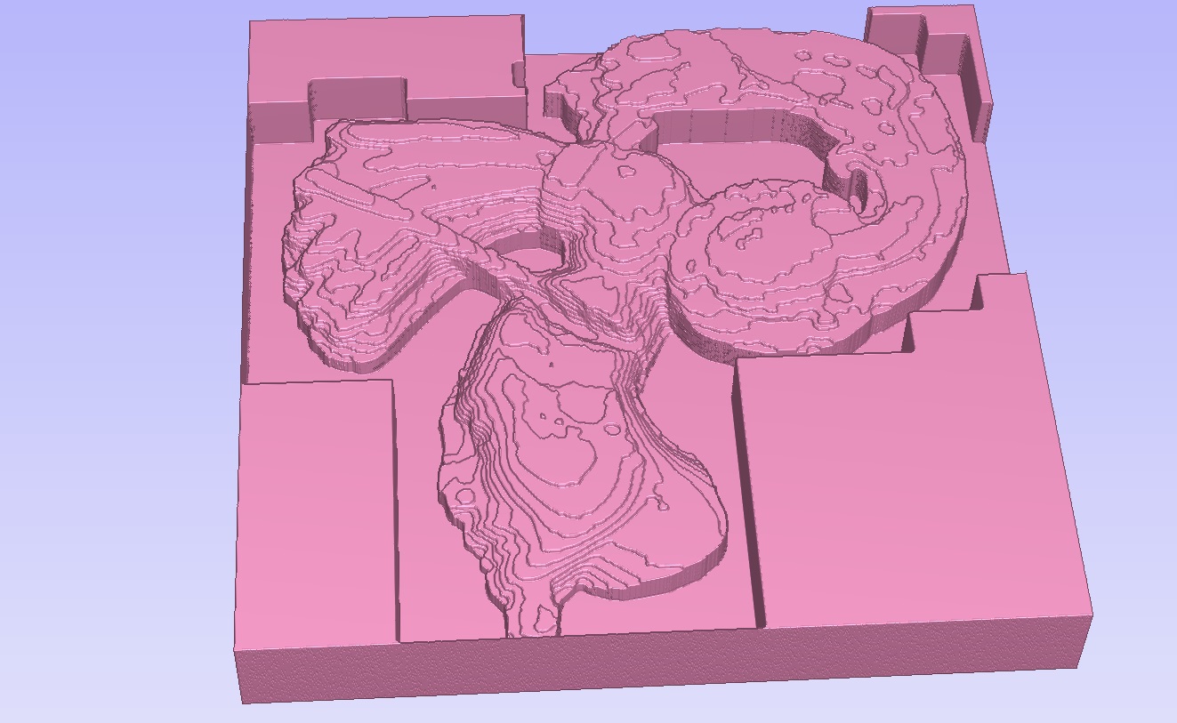
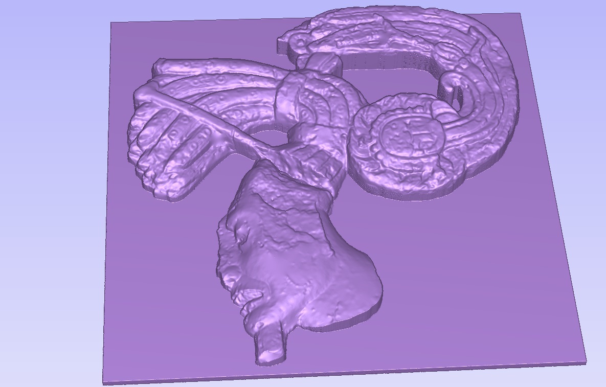
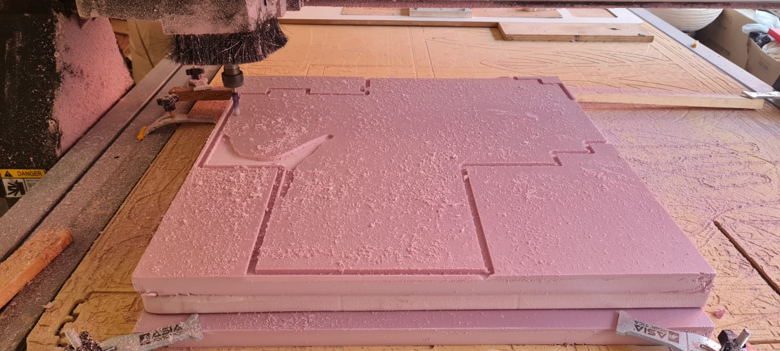
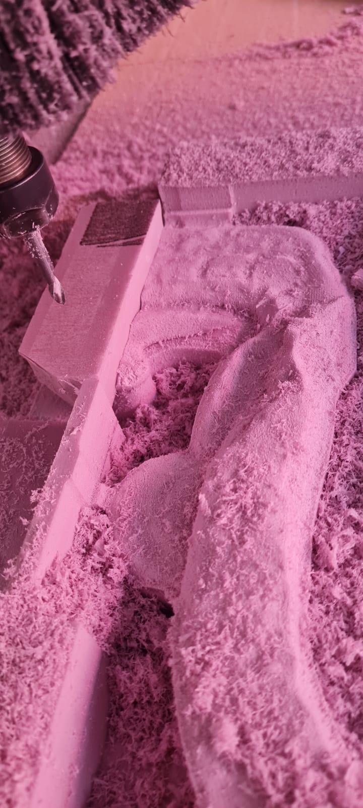
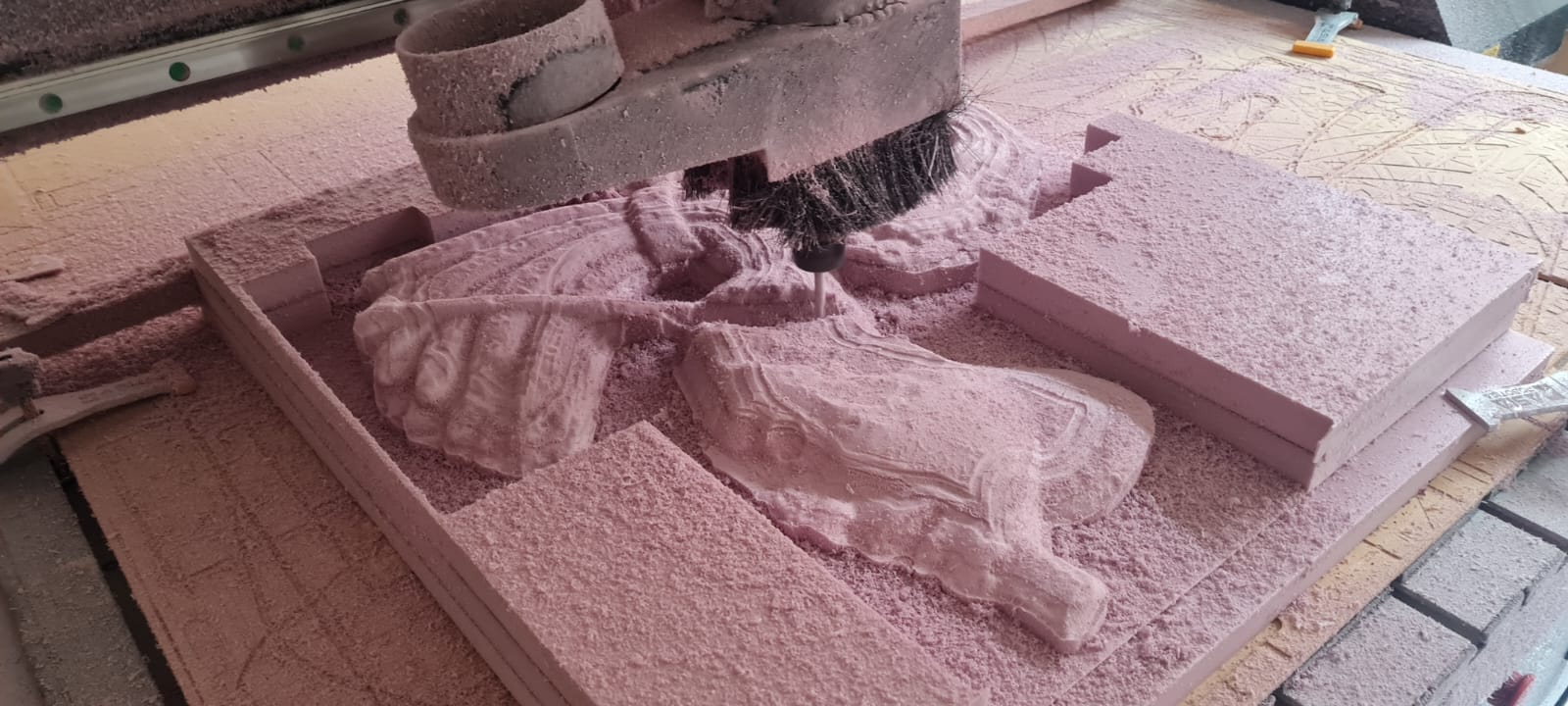
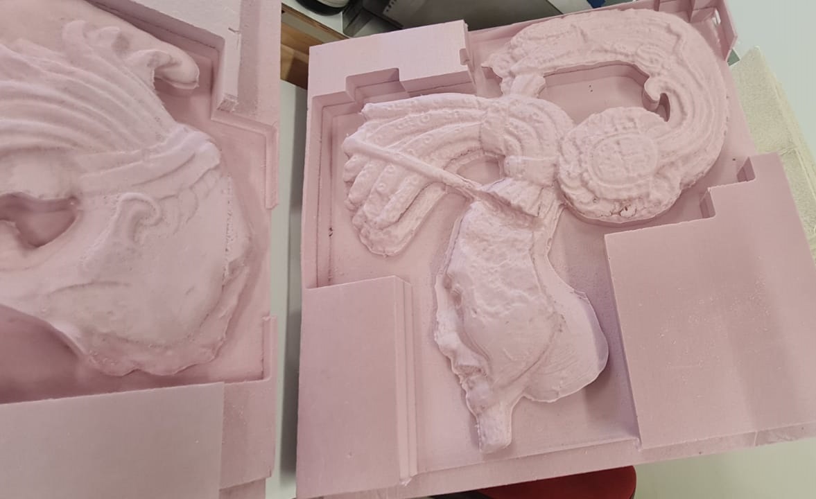
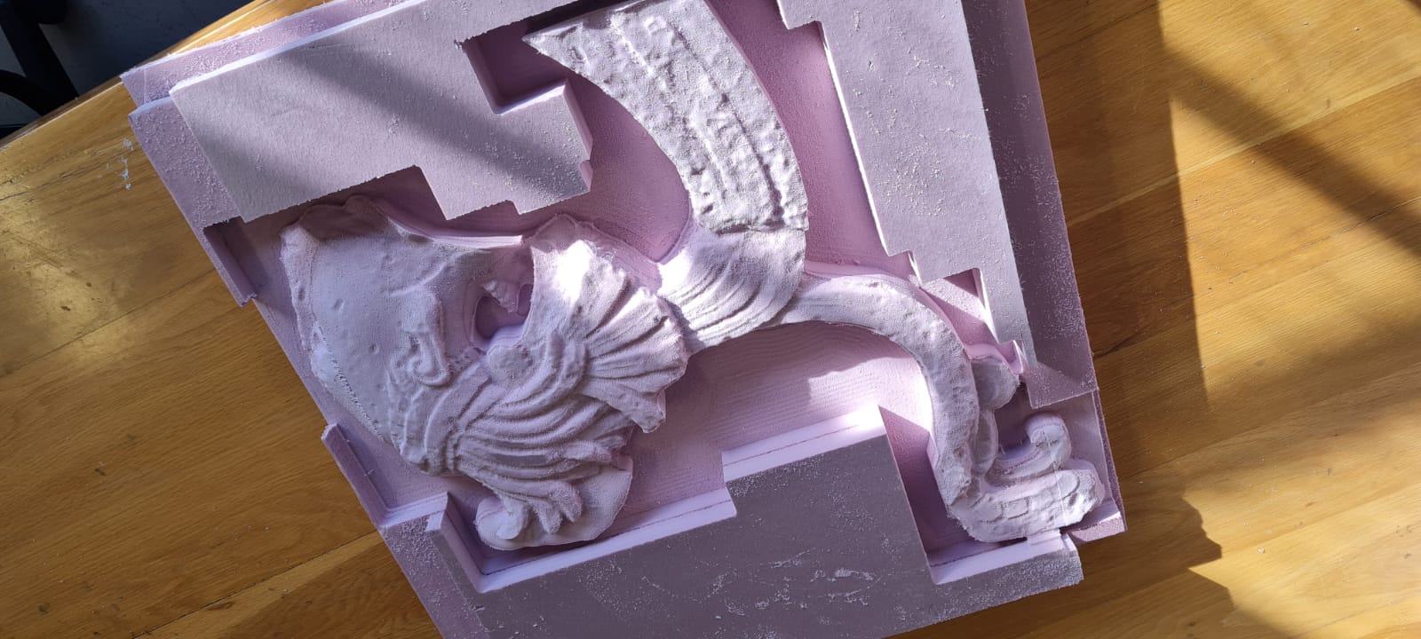
As mentioned on the Week_05: 3D Scanning and Printing assignment, we had the chance to colaborate with Museo Amparo for 3D scanning of an ancient Mayan throne, we also did a reproduction of some parts of the throne on insulating pink foam (I think is called Foamular), by following the same steps, first we selected the part to be reproduced, optimized it with Blender and then processed it through Vcarve. As the foam is quite soft, we had to cut really fast with a 1/2in bit with 4 flutes, which removed as much material as possible, and then have a second pass with more detail with a 1/8in Ball-end router bit which gave a soft and organic finish. Special thanks to Aristarco Cortés, Franco Robredo, Ramsés Orea, Ramiro Gutiérrez, Sergio "Search", Zeus Torres and all of the Museo Amparo team that made this project possible.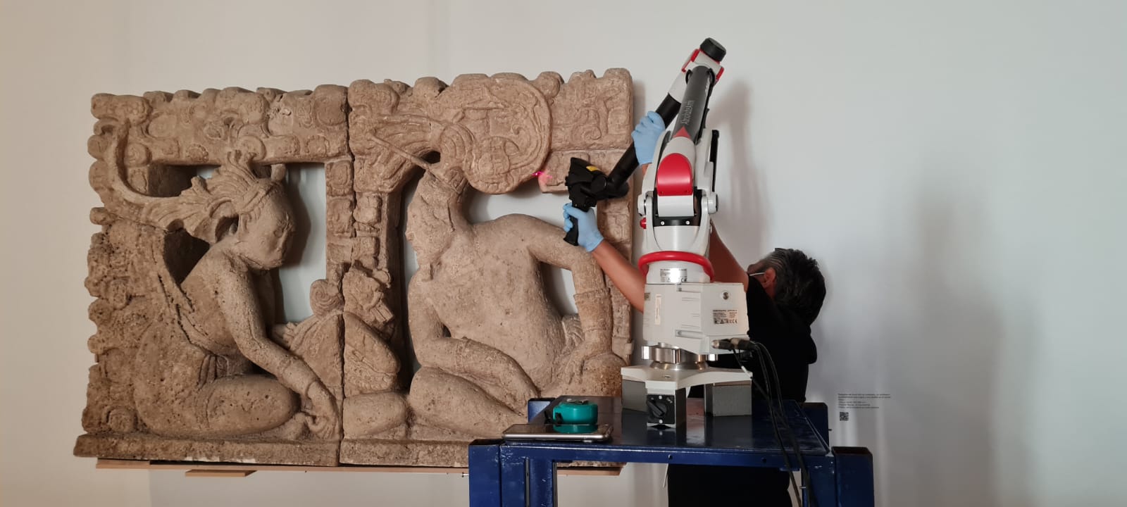
Thank you very much! See you next week.