Computer-Aided Cutting

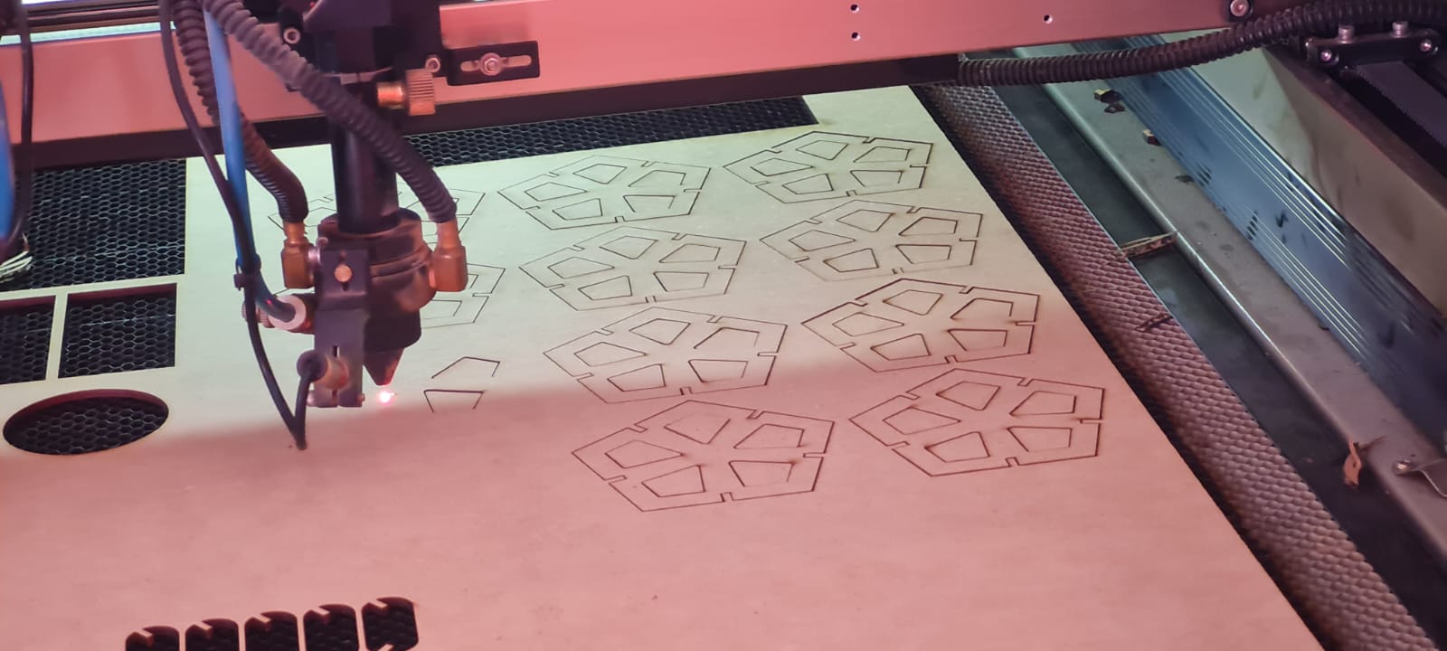
This week's assingment is Computer Aided Cutting, in which we use Laser-Cutting and Vinyl-Cutting machines for assembly and "sticker" creation.
Firstly we had to design and cut different kind of assemblies, most of which were perpendicular, for different applications. But in order to correctly design this pieces, 
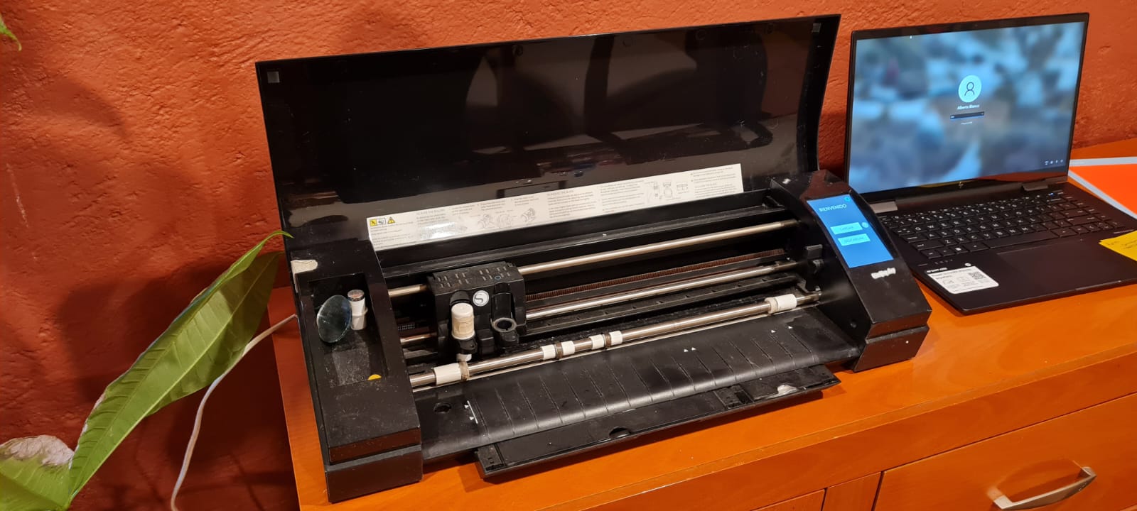
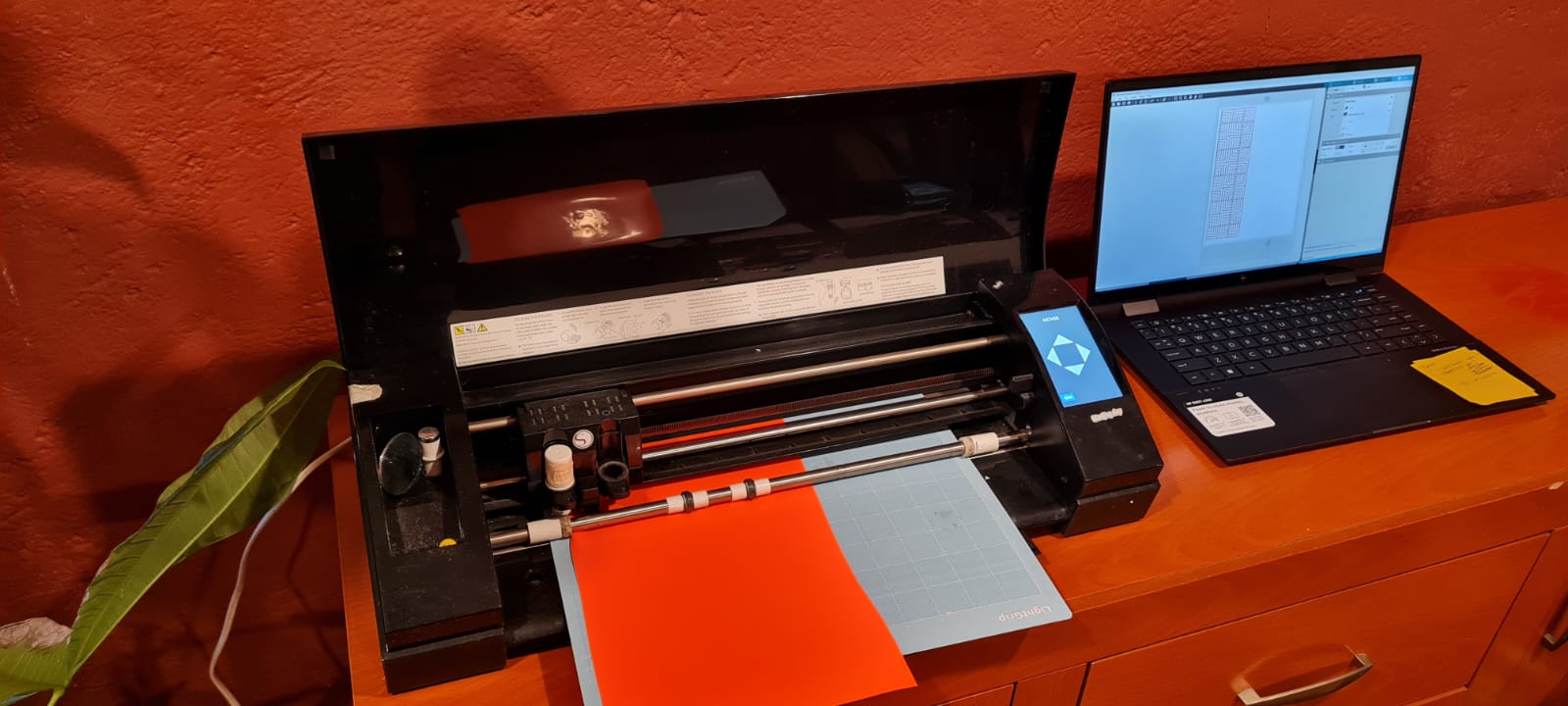
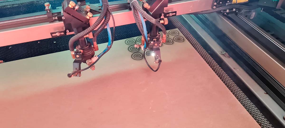
it is necessary to characterize each of the machines we work with. We have a CamFive CFL-CMA1390T which has a 100 Watt CO2 Laser Tube, and can move up to 250mm/s.

fusion360 espiralesFoto espirales

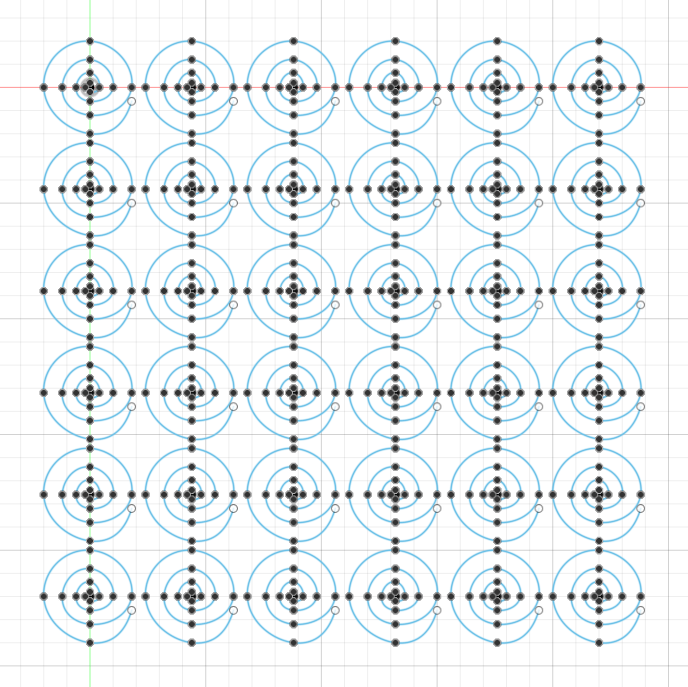
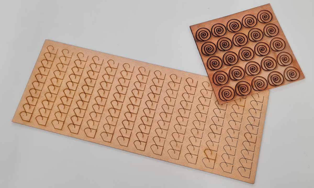
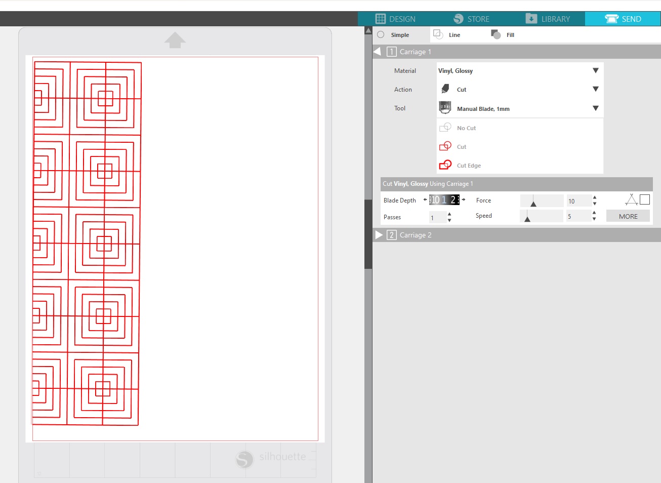
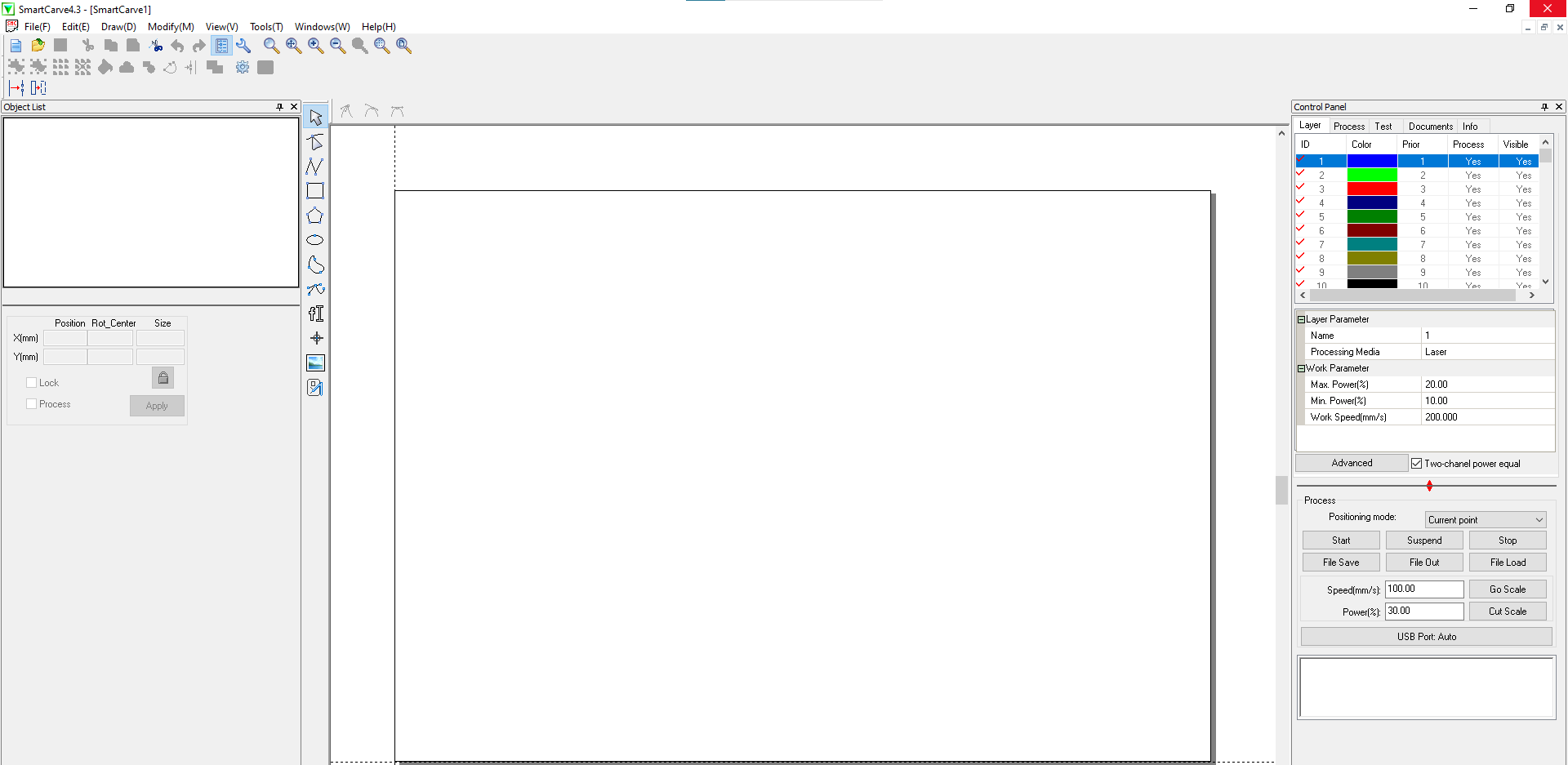
For the configuration of the machine, we use a software called SmartCarve(I couldn't find an official website for the download so be careful when downloading it, also you may need a USB drive key that works as a licence carrier) which has a simple interface where one can adjust the different parameters for cutting/engraving. The main parameters to be adjusted are: Speed of the laserhead, measured in mm/s, and power of the laser, measured in %. I used 80% power on the first one, with 50mm/s speed. On the same row I used 50mm/s increments, and for the next rows I decreased 10% of the power, with the same speeds. Interfaz SmartCarve
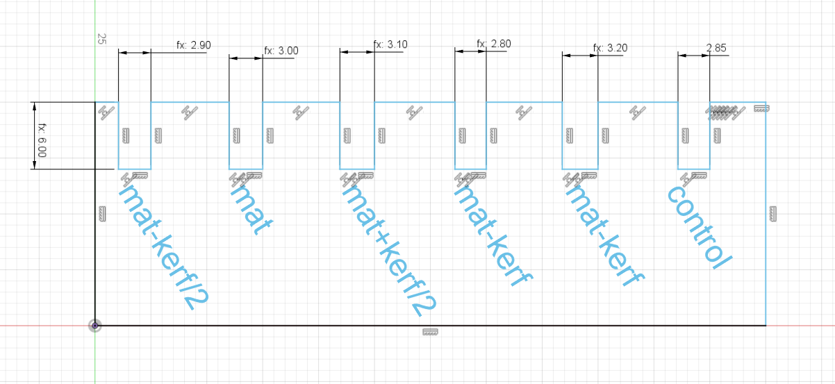
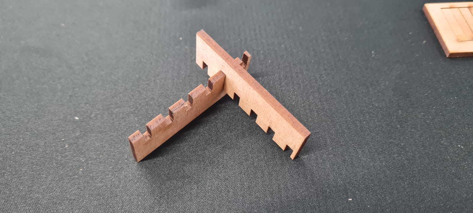
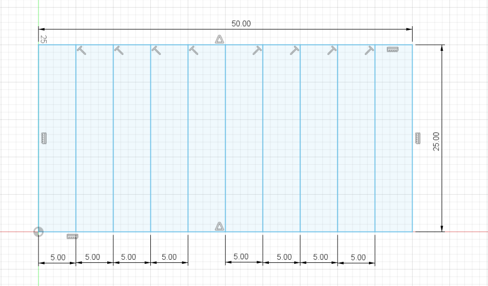
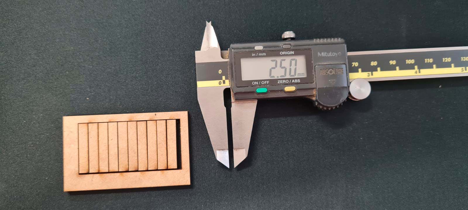
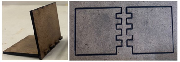
The next step for the propper characterization of the machine was to measure the Kerf. Kerf is the part of the material removed by the laser, with a clean cut it should be almost non-existing, however measurable. I started with a very simple design, a rectangle with 10 separations which will be cut through the laser. I knew which power and speed I needed to use thanks to the previous test (75%power and 20mm/s). Then it is possible to measure the gap that is created after the cut. In this case it was 2.24mm, and to calculate the exact Kerf one must divide it by the number of cuts, in this case it was 11, so the Kerf=.02mm.
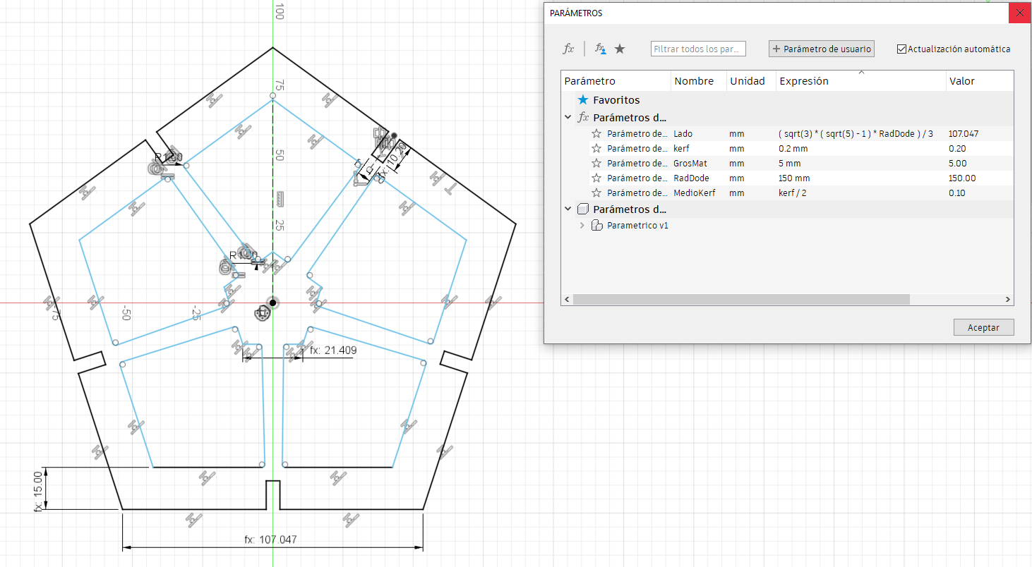
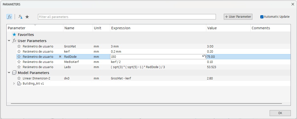
So now having the propper parameters for the cuts, the next task is to cut and assembly this pieces. It is necessary to consider the Kerf for every cut, so I came up with the formula:
For outside cuts: Nominal lenght + Kerf
For inside cuts: Nominal lenght - Kerf/2
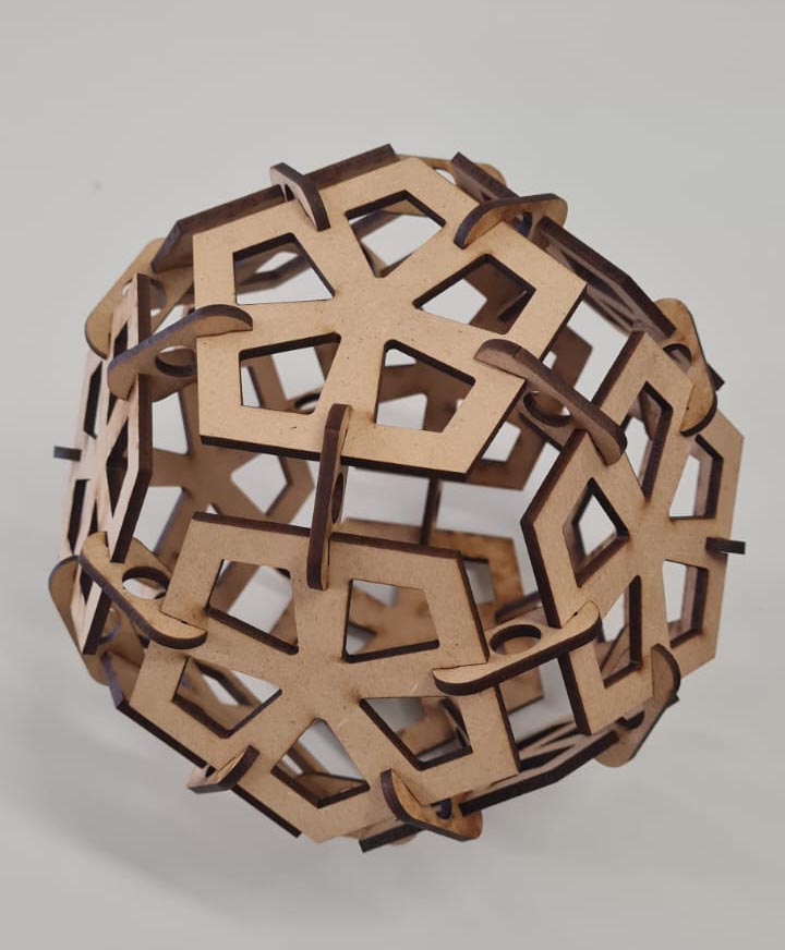
There are different kinds of joints so let's start with the beginning. The joints I designed and tested were the Pinned Joint and the Flexture Joint.
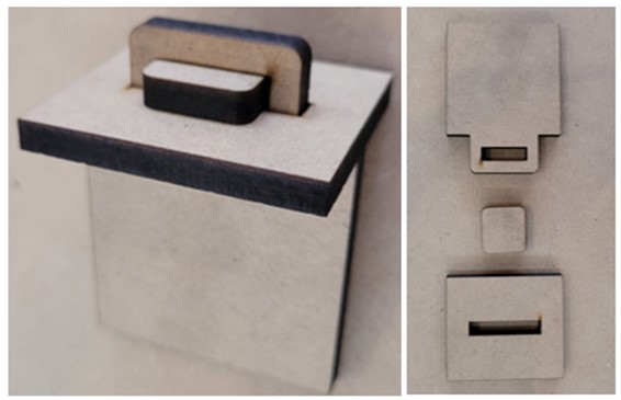
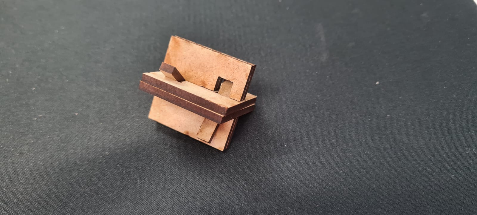
Pinned joint

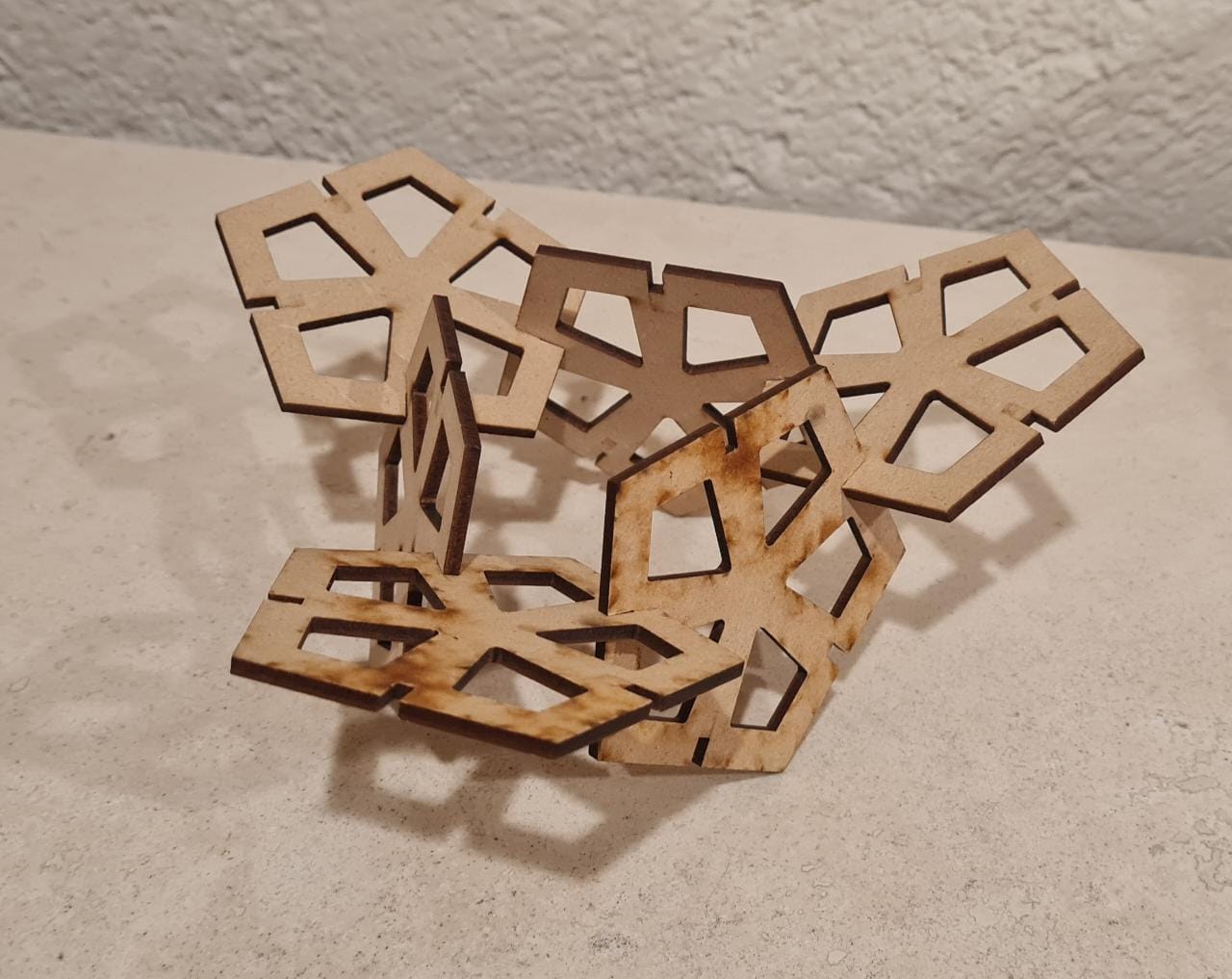
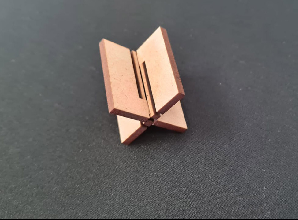
The Pinned joint works with a pin, as its name dictates, there is a cross whose center "square" lines up with another square, in which a pin is introduced for maximizing rigidity and stability. 
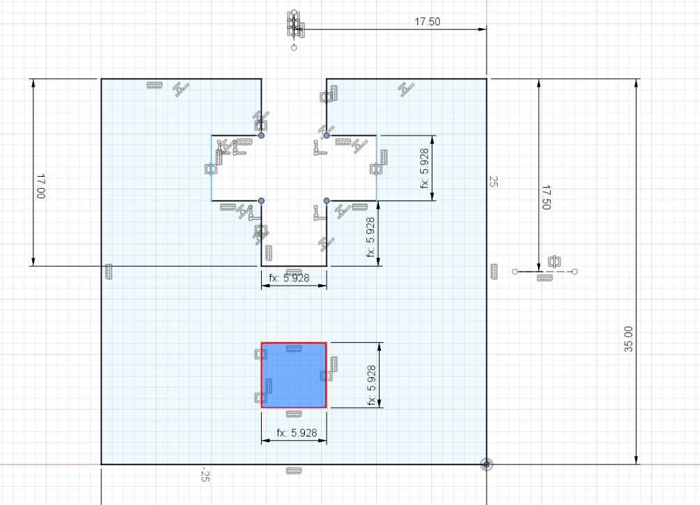
The challenges were figuring out how does this joint works, but after some deep examination, I came to the solution, the square from the shape and the empty space of the cross had to concurr in order for the pin to go through that hole, so I used the Symmetry constraint so they're positioned on the same distance, and fit perfectly.
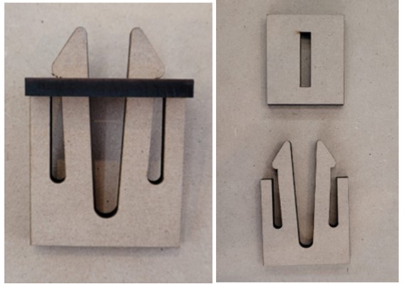
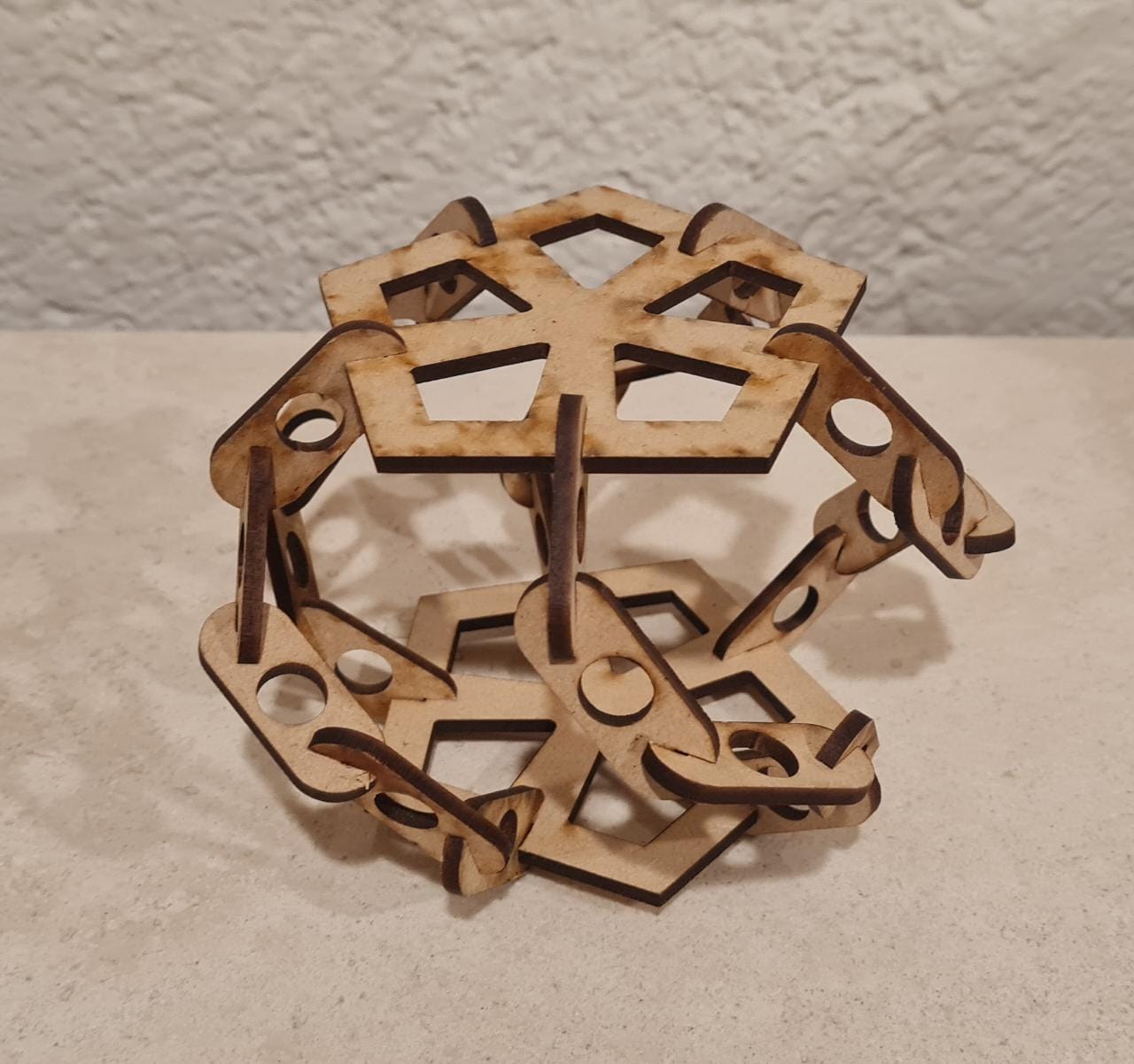
Flexture Joint

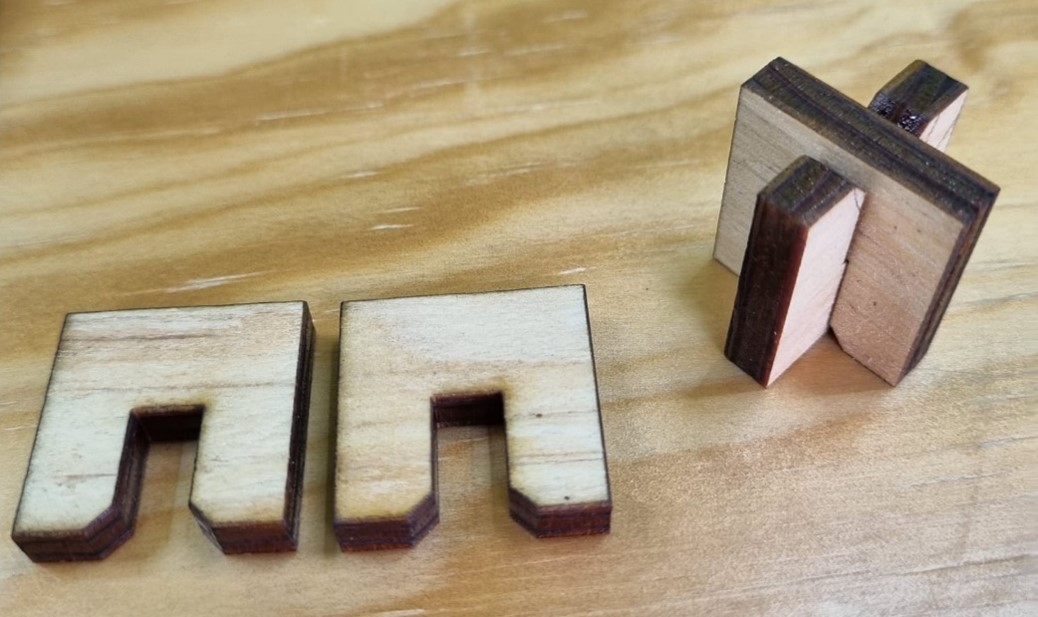
This joint consist on spring-like cuts which press the walls of the other part and ensures stability and strenght, as the flexible part of the joint secures it. 
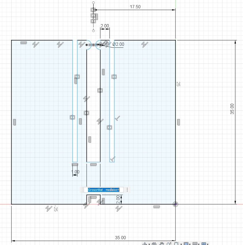
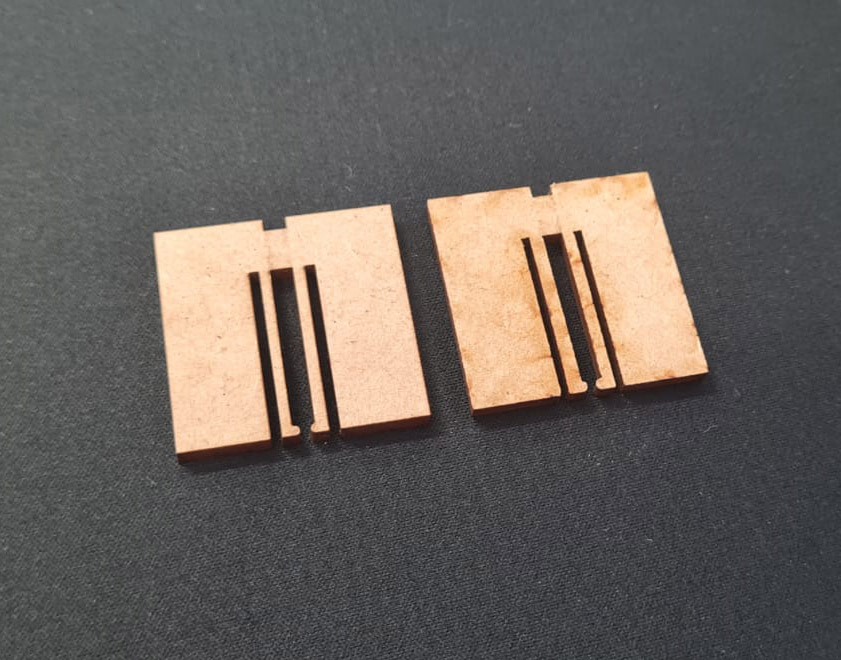
The challenges on this design were the small gap that lies between the flexible parts and the rest of the joint. However it was possible to determine with the possible movement of the flexture. The round parts lock with the small hole on the bottom, so it had to be designed as symmetrical as possible, again with the Symmetry constraint.

Group assignment

As a team we designed and tried different kind of joints which are presented bellow:
Finger and Chamfer joints
osciloscopio 2
multímetro 3

Wedge and Snap-fit joints
osciloscopio 2
multímetro 3


Parametric assembly

The next part of the assignment is the design of a parametric structure building kit with press-fit joints between the pieces. But what is Parametric Design?
It is defined as a design in which one can modify its measures and the end result should still be buildable. For example one could configure the thickness of the material as a variable, and then modify it according to the material to be used.
The build I thought of was some sort of dodecahedron, with small rounded pieces in between the faces of the volume. The parameters that can be reconfigured are the following:
Material Thickness Which will affect the thickness and depth of the PressFit joints.
Diameter of the whole volume This parameter will be defined by the diameter of each face.
Firstly I did some test for the propper PressFit dimensions so the final product could be as precise as possible. Pruebas pressfit fusion pruebas pressfit foto
The next part was to calculate/measure the angles between each face. I decided to add one joint for every side on the faces. I used the formula Internal angles = 360° * (number of edges - number of faces) which converted to 6480°=360°*(30-12) the result is to be divided between the number of faces * the number of side per face and ended up with 108°, which is the internal angle of every face. Modelo 3D dodecaedro
Having the measures and nominal design of each face, I then configured the parameters that can be modified and added them to the sketch.
The next (challenging) part was to figure out the relation between the radius of the whole volume and that of each face, so the next formula was to be figured out: [sqrt(3)*(1-sqrt(5)]*(Lenght of side/4). This formula then was solved for the side lenght and ended up with side=[[sqrt(3)*sqrt(5)-1]*Insphere Radius]/3. This was translated to the parametric design tool in Fusion 360.
For the finishing touches I designed the pressfit joint with the propper measures that I got from the previous test.
fusion, parámetro 3mmfusion, parametro de 5mm

The Parametric modification is done through the Modify dropdown menu, on the change parameters option. Each of the parameters can be modified on demand, but this time I will only change the insphere radius from 75mm to 150mm. So the whole
Parametrico 1
Parametrico 2
Parametrico 3

The shapes were cut, it needs 30 joint parts and 12 faces, it was configured for 3mm MDF with a Insphere radius of 75mm and the laser parameters were Speed: 35mm/s Power: 60%. Corte láserFoto producto final Foto final
Since the pieces and assemblies are the same dimensions, it is possible to arrange them in different ways for different results.
Ensamble distinto 1
Ensamble distinto 2

Vinyl Cutting


Vinyl is a very versatile polymer, however it's not recommended for laser cutting because it expels toxic and dangerous gases when burnt, so we use a different kind of machine, with the same working principle but instead of a laser head, it uses a blade that moves through a surface. Foto de la cortadora
The process was to first design the vector for the mug by measuring the circunference of it, and projecting it into a rectangle. Then we vectoriced the "holes" for the final design. Passing it to the cutting software is as easy as exporting it as a *.dxf* file and importing it into the Silhouette Studio. This software is quite friendly as it connects directly to the Silhouette Machines, in this case I used a Silhouette Cameo 3, so it knows its parameters for different kind of vinyls. Said parameters are the speed in which the material is cut, and the depth of the cut, so one can have thicker materials, or for propper sticker cutting. We first prepare the machine by pasting the vinyl into the cutting mat, which has an adhesive to prevent the material to move while cutting. Afterwards we send the design with the propper parameters and Voilà! We have a template for ceramics.
Software
Cortadora funcionando
The template was then pasted on the mug's surface and painted with glaze. The end product was fantastic. Foto de aplicando el vinil en la tazaTaza pintada Taza quemada
After this trial I thought of another use of the Machine Controlled Cutting and ended up designing a cool template for pressing on ceramics to obtain a piece with relieves. The process was more or less the same, first the template was designed and then configured through the laser cutting software, then cut on a 5mm MDF sheet. Afterwards the template was pressed on wet clay to imprint the pattern. It was left to dry for a couple of days and then kiln burnt. The final piece was a total success. Foto del corazon cortado en laserFoto del corazon impreso Foto del proceso de planchado y cortadoFoto del corazón quemado
Here are some more examples of what was done with ceramics and digital fabrication. Special thanks to Aristarco Cortés, Celina Juárez, Elizabeth Galindo and Javier Hernández. piezas salidas del horno
I included all of the files for the joints and the parametric building kit, as well as the vector for the mug, on the Downloadables webpage.